ZAP(R) & KBA Reverse Acting Rupture Discs
ZAP(R) & KBA Reverse Acting Rupture Discs
ZAP(R) & KBA Reverse Acting Rupture Discs

You also want an ePaper? Increase the reach of your titles
YUMPU automatically turns print PDFs into web optimized ePapers that Google loves.
<strong>ZAP</strong> ® *<br />
& <strong>KBA</strong><br />
<strong>Reverse</strong> <strong>Acting</strong> <strong>Rupture</strong> <strong>Discs</strong><br />
3-2220-3<br />
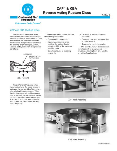
<strong>ZAP</strong> and <strong>KBA</strong> <strong>Rupture</strong> <strong>Discs</strong><br />
The <strong>ZAP</strong> and <strong>KBA</strong> reverse acting<br />
rupture discs utilize knife blades to open<br />
the rupture discs as reversal occurs. The<br />
rupture discs are differential pressure<br />
relief devices that provide instantaneous<br />
full opening for protecting equipment,<br />
vessels, and systems from overpressure<br />
conditions.<br />
KNIFE BLADE<br />
REVERSE ACTING<br />
RUPTURE DISC<br />
The reverse acting rupture disc has<br />
the following advantages:<br />
• Exceptional burst accuracy<br />
• A zero manufacturing range<br />
enabling the rupture disc to<br />
operate to 90% of the customer<br />
specified rating<br />
• Exceptional cyclic or pulsating<br />
service life<br />
• Capability to withstand vacuum<br />
conditions<br />
• Enhanced corrosion resistance due<br />
to thicker material<br />
• Designed for non-fragmentation<br />
<strong>ZAP</strong> and <strong>KBA</strong> rupture discs respond<br />
in milliseconds to overpressure<br />
situations, allowing them to be used in<br />
a variety of applications.<br />
MEDIA PRESSURE<br />
The <strong>ZAP</strong> and <strong>KBA</strong> reverse acting<br />
rupture discs have the media pressure<br />
acting on the convex side of the rupture<br />
disc, placing it in compression. When<br />
the burst pressure rating of the rupture<br />
disc is reached, the compression loading<br />
on the rupture disc causes it to reverse,<br />
snapping it through its neutral position<br />
and through the knife blades resulting<br />
in a full opening.<br />
<strong>ZAP</strong> Insert Assembly<br />
<strong>KBA</strong> Insert Assembly<br />
*U.S. Patent 3,922,767<br />
1
<strong>ZAP</strong> AND <strong>KBA</strong> RUPTURE DISCS<br />
Vacuum Conditions<br />
<strong>ZAP</strong> <strong>Reverse</strong> <strong>Acting</strong> <strong>Rupture</strong> Disc<br />
The <strong>ZAP</strong> and <strong>KBA</strong> rupture discs are<br />
designed to withstand full vacuum<br />
without affecting the burst pressure<br />
setting or reliability. No additional<br />
components, such as a vacuum support,<br />
are required.<br />
Corrosion Protection<br />
The <strong>ZAP</strong> and <strong>KBA</strong> rupture discs are<br />
superior for use in a corrosive media or<br />
environment. Versatile material selection<br />
and use of thicker rupture disc materials<br />
contribute to the superior corrosion<br />
resistance. A Teflon ® * liner may be used<br />
on the process side of the <strong>ZAP</strong> and <strong>KBA</strong><br />
rupture discs for additional corrosion<br />
protection.<br />
Seal Load Sensitivity<br />
Over-torquing will not affect the<br />
burst accuracy of the <strong>ZAP</strong> <strong>Rupture</strong> Disc.<br />
Continental Disc's encapsulating rings,<br />
proven to minimize seal load (bolt torque)<br />
sensitivity, are included on the <strong>ZAP</strong><br />
<strong>Rupture</strong> Disc.<br />
1. The encapsulating rings hold the<br />
<strong>ZAP</strong> <strong>Rupture</strong> Disc in the proper<br />
location and are permanently<br />
attached to the rupture disc.<br />
2. They provide a base to accept<br />
reasonable over-torquing of the<br />
companion flange bolts while<br />
protecting the rupture disc from<br />
being damaged.<br />
3. They provide a superior metal-tometal<br />
sealing surface.<br />
OUTLET<br />
FLANGE<br />
The <strong>ZAP</strong> <strong>Rupture</strong> Disc is available<br />
in nominal sizes ranging from<br />
1" through 8" (25 mm through<br />
200 mm). Proven features include:<br />
• +/- 5% accuracy for burst<br />
pressures 40 psig and above<br />
• Operation to 90% of the<br />
rated burst pressure<br />
• Zero (0) manufacturing range<br />
• Exceptional cyclic or pulsating<br />
service life<br />
• Designed for non-fragmentation<br />
• Encapsulating rings provide<br />
perfect alignment and minimize<br />
seal load sensitivity<br />
• May be used in <strong>ZAP</strong> Holders<br />
having replaceable knife blades<br />
or optional welded-in knife blades<br />
• May be operated under a<br />
full vacuum or backpressure<br />
to 110% of the rated burst<br />
pressure<br />
HOLDER<br />
OUTLET<br />
RUPTURE<br />
DISC<br />
• Standard materials include<br />
Aluminum, Nickel, Monel**,<br />
Inconel** or 316 Stainless Steel.<br />
Other materials available upon<br />
request<br />
• Conformance to national and<br />
international codes including<br />
ASME Section III or VIII, DIN,<br />
BSI, JIS, ISO,or other codes<br />
as required<br />
• Excellent for isolating safety<br />
relief valves<br />
• For use in gaseous service<br />
• Optional J-Hook makes rupture<br />
disc and holder installation<br />
virtually error-proof<br />
• Optional three-dimensional<br />
flow direction tag permanently<br />
attached to the <strong>ZAP</strong> <strong>Rupture</strong> Disc<br />
REPLACEABLE<br />
KNIFE BLADE<br />
ASSEMBLY<br />
SPIRAL WOUND<br />
GASKET<br />
RUPTURE<br />
DISC TAG<br />
(OPTIONAL)<br />
<strong>ZAP</strong><br />
ENCAPSULATING<br />
RINGS<br />
HOLDER<br />
INLET<br />
<strong>ZAP</strong><br />
RUPTURE<br />
DISC<br />
INLET<br />
FLANGE<br />
FLOW DIRECTION<br />
J-HOOK<br />
(OPTIONAL)<br />
<strong>ZAP</strong> <strong>Reverse</strong> <strong>Acting</strong> <strong>Rupture</strong> Disc Assembly<br />
2<br />
* Teflon is a registered trademark of the DuPont Corporation.<br />
** Monel and Inconel are registered trademarks of the Inco family of companies.
SPECIFICATIONS<br />
<strong>KBA</strong> <strong>Reverse</strong> <strong>Acting</strong><br />
<strong>Rupture</strong> Disc<br />
The <strong>KBA</strong> <strong>Rupture</strong> Disc is available in<br />
nominal sizes ranging from 1" through<br />
32" (25 mm - 800 mm).<br />
Features include:<br />
• +/- 5% accuracy for burst pressures<br />
40 psig and above<br />
• Operation to 90% of the rated burst<br />
pressure<br />
• Zero (0) manufacturing range<br />
• Exceptional cyclic or pulsating<br />
service life<br />
• May be operated under a full<br />
vacuum or backpressure to 110%<br />
of the rated burst pressure<br />
• Designed for non-fragmentation<br />
• Conformance to national and<br />
international codes including ASME<br />
Section III or VIII, DIN, BSI, JIS, ISO,<br />
or other codes as required<br />
• Excellent for isolating safety relief<br />
valves<br />
• Standard materials include<br />
Aluminum, Nickel, Monel, Inconel or<br />
316 Stainless Steel. Other materials<br />
available upon request<br />
• For use in gaseous service<br />
• Optional J-Hook makes rupture disc<br />
and holder installation virtually<br />
error-proof<br />
• Optional three-dimensional<br />
flow direction tag permanently<br />
attached to the <strong>KBA</strong> <strong>Rupture</strong> Disc<br />
HOLDER<br />
OUTLET<br />
RUPTURE<br />
DISC<br />
KNIFE BLADE<br />
ASSEMBLY<br />
RUPTURE<br />
DISC TAG<br />
(OPTIONAL)<br />
Manufacturing Range<br />
As a standard, the <strong>ZAP</strong> and <strong>KBA</strong><br />
rupture discs are designed with a zero<br />
manufacturing range. This enables the<br />
rupture disc to operate at 90% of the<br />
customer's specified rating.<br />
For rated burst pressures below<br />
40 psig, the recommended operating<br />
pressure is 90% of the value of the rated<br />
(stamped) burst pressure minus the burst<br />
tolerance. (i.e., [stamped rating minus<br />
the 2 psig burst tolerance] x .90.)<br />
<strong>Rupture</strong> Disc Materials<br />
The <strong>ZAP</strong> and <strong>KBA</strong> rupture discs are<br />
available in Aluminum, Nickel, Monel,<br />
Inconel and 316 Stainless Steel. Other<br />
materials are available upon request.<br />
Table I - Burst Tolerance<br />
psig<br />
Specified Burst<br />
Pressure Rating<br />
barg<br />
Burst Tolerance<br />
The <strong>ZAP</strong> and <strong>KBA</strong> rupture discs are<br />
designed with a burst tolerance as<br />
shown in Table I. A minimum of two<br />
burst tests per lot of rupture discs are<br />
conducted to determine conformance<br />
with the customer's specified burst<br />
pressure. The rated (stamped) burst<br />
pressure appearing on the tag is the<br />
customer's specified burst pressure.<br />
Burst<br />
Tolerance<br />
Under 40 Under 2.8 ± 2 psig / ± 0.14 barg<br />
40 and above 2.8 and above ± 5%<br />
Table II - <strong>Rupture</strong> Disc Temperature Limits<br />
Recommended Maximum<br />
<strong>Rupture</strong><br />
Disc<br />
Temperature<br />
Material Fahrenheit Celsius<br />
Teflon Liners<br />
PFA Teflon 500° 260°<br />
FEP Teflon 400° 204°<br />
Nickel, Monel 800° 427°<br />
316 Stainless Steel 900° 482°<br />
Inconel 1000° 538°<br />
Aluminum 260° 127°<br />
HOLDER<br />
INLET<br />
J-HOOK<br />
(OPTIONAL)<br />
FLOW DIRECTION<br />
<strong>KBA</strong> <strong>Reverse</strong> <strong>Acting</strong> <strong>Rupture</strong> Disc<br />
Assembly<br />
3
OPTIONAL FEATURES<br />
Tagging<br />
Continental Disc Corporation's<br />
permanently attached three-dimensional<br />
flow direction tag may be attached to the<br />
<strong>ZAP</strong> or <strong>KBA</strong> rupture discs. The 3-D flow<br />
tag has "DIRECTIONAL FLOW<br />
ARROWS" on three sides, providing<br />
immediate visual verification that the<br />
rupture disc is properly oriented in the<br />
system. This tag is a customer option<br />
and should be requested at the time of<br />
order. A millslot in the holder outlet is<br />
required when using <strong>KBA</strong> or <strong>ZAP</strong> rupture<br />
discs with attached 3-D flow tag.<br />
A flat, stainless steel tag is normally<br />
supplied with the <strong>ZAP</strong> and <strong>KBA</strong> rupture<br />
disc as a separate item. This tag may be<br />
attached to the companion flanges at the<br />
time the assembly is installed, providing<br />
pertinent burst pressure information at<br />
the rupture disc location.<br />
The <strong>ZAP</strong> and <strong>KBA</strong> Holders have a<br />
stainless steel nameplate, indicating flow<br />
direction, permanently attached to the<br />
inlet and outlet. In addition, whenever<br />
customer identification tagging is<br />
required, a stainless steel CUSTOMER<br />
IDENTIFICATION TAG is permanently<br />
attached at no extra charge.<br />
The combination of the nameplates<br />
and the 3-D flow tag is exclusive with<br />
Continental Disc Corporation.<br />
Burst Disc Indicator (B.D.I. ® * ) Alarm System<br />
The Continental Disc state-of-the-art<br />
alarm system is designed specifically for<br />
use with C.D.C.'s <strong>ZAP</strong> and <strong>KBA</strong> rupture<br />
discs.<br />
The B.D.I. Alarm System consists<br />
of an alarm strip, which can interface with<br />
a monitoring unit, computer, annunciator<br />
panel, control panel, or other equipment.<br />
The alarm system is activated by the<br />
opening of the <strong>ZAP</strong> or <strong>KBA</strong> rupture disc.<br />
The B.D.I. Alarm System is a normally<br />
closed, low-powered circuit. When a<br />
rupture disc opens, the B.D.I. Alarm Strip<br />
is severed, interrupting the circuit, which<br />
activates a monitoring device. This<br />
device then signals that an overpressure<br />
condition has occurred and that media is<br />
venting.<br />
• The B.D.I. Alarm System signals<br />
instantly when a rupture disc has<br />
opened, giving operating personnel<br />
a positive signal of fugitive emissions<br />
and / or the occurrence of an<br />
overpressure relief condition.<br />
• The B.D.I. Alarm System signals<br />
emergency equipment, control room,<br />
and / or operating personnel to alter<br />
or stop a process.<br />
• The B.D.I. Alarm System prevents an<br />
undetected open vent line, once an<br />
overpressure condition occurs.<br />
• FM (Factory Mutual) approved,<br />
intrinsically safe monitors are<br />
available.<br />
* Burst Disc Indicator (B.D.I.) Alarm System incorporates U.S. patent no. Re. 34,308 and 4,408,194;<br />
Australia patent no. 539415; Germany patent no. 3174227.0; Canada patent no. 1199990;<br />
Belgium, France and United Kingdom patent no. EP 0 033 867; Japan patent no. 2032464.<br />
4
PRESSURE RANGES<br />
Table III - <strong>ZAP</strong> <strong>Rupture</strong> Disc Minimum/Maximum Pressures at 72°F (22°C)<br />
When Used With <strong>ZAP</strong><br />
When Used With <strong>ZAP</strong><br />
Nominal Replaceable Knife Blade Holder Welded-In Knife Blade Holder<br />
Size<br />
Aluminum Nickel/Monel Inconel/316SS Aluminum Nickel/Monel Inconel/316SS<br />
Min Max Min Max Min Max Min Max Min Max Min Max<br />
1 in. — — — — — — 50 225 100 750 110 1000<br />
25 mm — — — — — — 3.5 15.5 6.9 51.7 7.6 69.0<br />
1 1/2 in. 45 225 90 725 90 850 45 225 90 725 90 1000<br />
40 mm 3.1 15.5 6.2 50.0 6.2 58.6 3.1 15.5 6.2 50.0 6.2 69.0<br />
2 in. 35 150 60 700 60 800 35 150 69 700 60 1000<br />
50 mm 2.4 10.3 4.1 48.3 4.1 55.2 2.4 10.3 4.1 48.3 4.1 69.0<br />
3 in. 30 150 50 675 50 750 30 150 50 675 50 1000<br />
80 mm 2.1 10.3 3.5 46.6 3.5 51.7 2.1 10.3 3.5 46.6 3.5 69.0<br />
4 in. 25 100 45 625 50 725 25 100 45 625 50 800<br />
100 mm 1.7 6.9 3.1 43.1 3.5 50.0 1.7 6.9 3.1 43.1 3.5 55.2<br />
6 in. 20 75 35 300 40 350 20 75 35 500 40 700<br />
150 mm 1.4 5.2 2.4 20.7 2.8 24.1 1.4 5.2 2.4 34.5 2.8 48.3<br />
8 in. 15 60 25 225 25 275 15 60 25 300 25 350<br />
200 mm 1.03 4.1 1.7 15.5 1.7 20.0 1.03 4.1 1.7 20.7 1.0 24.1<br />
Notes For Table III:<br />
1. Stainless steel inlet and outlet rings are standard. For other ring materials, consult your Continental Disc representative or the factory.<br />
2. Teflon liners and protective covers are available as an option.<br />
3. White bar indicates "psig," gray bar indicates "barg."<br />
Code Compliance<br />
C.D.C. will provide <strong>ZAP</strong> and <strong>KBA</strong><br />
rupture discs to national or international<br />
code requirements when specified by the<br />
customer. C.D.C. will manufacture,<br />
temperature test, and mark rupture discs<br />
in compliance with the requested code.<br />
Product may be supplied to ASME Section<br />
III or VIII, ISO, DIN, BSI, JIS, or other<br />
codes as required.<br />
Continental Disc Corporation has been<br />
accredited and is authorized by the ASME<br />
Code to utilize the Code Symbol<br />
Stamp for product built in accordance with<br />
the requirements of the ASME Boiler and<br />
Pressure Vessel Code, Section VIII,<br />
Division 1.<br />
The certified flow resistance value (K R<br />
)<br />
and minimum net flow area value of the<br />
<strong>KBA</strong> <strong>Rupture</strong> Disc and the <strong>ZAP</strong> <strong>Rupture</strong><br />
Disc are available from Continental Disc<br />
Corporation or The National Board of<br />
Boiler and Pressure Vessel Inspectors.<br />
C.D.C. maintains an ASME accepted<br />
flow laboratory to conduct flow testing for<br />
rupture discs, relief valves, and rupture<br />
disc/valve combinations.<br />
5
PRESSURE RANGES<br />
Table IV - <strong>KBA</strong> <strong>Rupture</strong> Disc Minimum/Maximum Pressures at 72°F (22°C)<br />
Nominal<br />
Size<br />
Aluminum Nickel/Monel Inconel/316SS<br />
Min Max Min Max Min Max<br />
1 in. 50 225 100 1000 110 1000<br />
25 mm 3.4 15.5 6.9 69.0 7.6 69.0<br />
1 1/2 in. 45 225 90 1000 90 1000<br />
40 mm 3.1 15.5 6.2 69.0 6.2 69.0<br />
2 in. 35 150 60 900 60 1000<br />
50 mm 2.4 10.3 4.1 62.1 4.1 69.0<br />
3 in. 30 150 50 800 50 1000<br />
80 mm 2.1 10.3 3.4 55.2 3.4 69.0<br />
4 in. 25 100 45 700 50 800<br />
100 mm 1.7 6.9 3.1 48.3 3.4 55.2<br />
6 in. 20 75 35 600 40 700<br />
150 mm 1.4 5.2 2.4 41.4 2.8 48.3<br />
8 in. 15 60 25 350 25 400<br />
200 mm 1.03 4.1 1.7 24.1 1.7 27.6<br />
10 in. — — 20 300 25 375<br />
250 mm — — 1.4 20.7 1.7 25.9<br />
12 in. — — 20 200 25 250<br />
300 mm — — 1.4 13.8 1.7 17.2<br />
14 in. — — 20 150 25 200<br />
350 mm — — 1.4 10.3 1.7 13.8<br />
16 in. — — 20 150 25 200<br />
400 mm — — 1.4 10.3 1.7 13.8<br />
18 in. — — 20 150 25 200<br />
450 mm — — 1.4 10.3 1.7 13.8<br />
20 in. — — 20 100 25 200<br />
500 mm — — 1.4 6.9 1.7 13.8<br />
24 in. — — 20 100 25 150<br />
600 mm — — 1.4 6.9 1.7 10.3<br />
28 in. — — 20 55 25 70<br />
700 mm — — 1.4 3.8 1.7 4.8<br />
30 in. — — 20 50 25 65<br />
750 mm — — 1.4 3.4 1.7 4.5<br />
32 in. — — 20 45 25 60<br />
800 mm — — 1.4 3.1 1.7 4.1<br />
Notes For Table IV:<br />
1. Contact Continental Disc Corporation for information on other sizes.<br />
2. Teflon liners and protective covers are available as an option.<br />
3. White bar indicates "psig," gray bar indicates "barg."<br />
6
<strong>ZAP</strong> AND <strong>KBA</strong> RUPTURE DISC HOLDERS<br />
<strong>ZAP</strong> and <strong>KBA</strong> Holders<br />
The <strong>ZAP</strong> and <strong>KBA</strong> Holders are insert<br />
type, designed for superior sealing<br />
capability.<br />
The <strong>ZAP</strong> Holder Assembly is<br />
designed with replaceable knife blades in<br />
sizes 1 1/2" through 8" (40 mm through<br />
200 mm). This provides quick and easy<br />
blade replacement at the time a <strong>ZAP</strong><br />
<strong>Rupture</strong> Disc is changed. A nonasbestos,<br />
spiral wound gasket is<br />
provided between the holder outlet and<br />
replaceable knife blades to assure a<br />
seal-tight assembly.<br />
The 1" (25 mm) <strong>ZAP</strong> Holder has a<br />
welded-in knife blade. As an option, the<br />
larger sized <strong>ZAP</strong> Holders are offered with<br />
welded-in knife blades.<br />
The <strong>KBA</strong> Holders are supplied with<br />
welded-in knife blades on all sizes.<br />
An optional J-Hook provides easy<br />
alignment and assures proper directional<br />
installation.<br />
Holder Outside<br />
Diameter<br />
Holder Specifications<br />
Holders are available for ANSI, DIN,<br />
or JIS class flanges as shown in Table V.<br />
Consult factory for holders to fit other<br />
national or international standards.<br />
A millslot is machined in the holder outlet<br />
to accommodate the rupture disc's 3-D<br />
flow tag.<br />
Materials: Carbon steel, 316SS,<br />
304SS, Monel, Inconel and Hastelloy-C.<br />
Other materials are available upon<br />
request.<br />
Accessories: Nipple and tee,<br />
excess flow valve, pressure gauge.<br />
Options: Gauge tap, special facing,<br />
Teflon coating, millslot for B.D.I. Alarm<br />
System (<strong>ZAP</strong> only).<br />
Height<br />
Table V - <strong>ZAP</strong> Insert Holder With Replaceable Blades Dimensions and Weights<br />
Outside Diameter of Holder (1) Height of Holder Weight of Holder<br />
(approximate) (3)<br />
Nominal ANSI DIN JIS Replaceable<br />
Size Class O.D. Class O.D. Class O.D. Blades (2) ANSI DIN JIS<br />
inches mm mm inches mm lbs kgs lbs kgs lbs kgs<br />
1 1/2 in. 150 3.25 10/40 92,2 10/20 86 2.19 56 3.0 1,4 4.0 1,8 3.5 1,6<br />
40 mm 300/600 3.63 — — 30/40 97 2.19 56 4.5 2,0 — — 4.8 2,2<br />
2 in. 150 4.00 10/40 108 10/20 101,6 2.19 56 4.5 2,0 5.0 2,3 4.5 2,0<br />
50 mm 300/600 4.25 64 111 30/40 111 2.19 56 5.5 2,5 6.1 2,8 5.8 2,6<br />
3 in.<br />
80 mm<br />
4 in.<br />
100 mm<br />
6 in.<br />
150 mm<br />
8 in.<br />
200 mm<br />
150 5.25 10/40 142 — — 2.32 59 7.5 3,4 9.0 4,1 — —<br />
— — — — 16/20 137 2.32 59 — — — — 8.2 3,7<br />
300/600 5.75 64 146,1 30/40 146,1 2.32 59 10 4,5 9.8 4,4 10 4,5<br />
150 6.75 — — — — 2.56 65 13 5,9 — — — —<br />
300 7.00 — — — — 2.56 65 15 6,8 — — — —<br />
— — — — 40 180 2.56 65 — — — — 16 7,3<br />
600 7.50 64 173 — — 2.56 65 19 8,6 14 6,4 — —<br />
150 8.63 — — — — 3.13 80 22 9,9 — — — —<br />
— — — — 16/20 235 3.13 80 — — — — 29 13<br />
300 9.75 25/40 223 30 247,7 3.13 80 34 15 23 11 35 16<br />
— — — — 40 262 3.13 80 — — — — 42 19<br />
600 10.38 — — — — 3.13 80 43 20 — — — —<br />
150 10.88 — — — — 3.79 96 41 19 — — — —<br />
— — — — 16/20 280 3.79 96 — — — — 41 19<br />
300 12.00 25 283 30 293 3.79 96 58 26 43 20 50 23<br />
— — 40 290 40 312 3.79 96 — — 48 22 64 29<br />
Notes:<br />
1. Consult factory for other ANSI, DIN, or JIS class flanges.<br />
2. Dimension includes 1/8" for spiral wound gasket.<br />
3. Weights do not include studs and nuts.<br />
4. If a B.D.I. Alarm is specified for a <strong>ZAP</strong> Assembly, a<br />
millslot is required in the holder.<br />
5. If 3-D flow tag is attached to a <strong>ZAP</strong> <strong>Rupture</strong> Disc, a<br />
millslot is required in the holder.<br />
7
<strong>ZAP</strong> RUPTURE DISC HOLDERS<br />
Holder Outside<br />
Diameter<br />
Height<br />
Table VI - <strong>ZAP</strong> Insert Holder With Welded In Blades Dimensions and Weights<br />
Outside Diameter of Holder (1) Height of Holder Weight of Holder<br />
(approximate) (2)<br />
Nominal ANSI DIN JIS<br />
Size Class O.D. Class O.D. Class O.D. Welded Blades ANSI DIN JIS<br />
inches mm mm inches mm lbs kg lbs kg lbs kg<br />
1 in.<br />
25 mm<br />
1 1/2 in.<br />
40 mm<br />
150 2.50 10/40 69,9 10/20 69,9 2.03 52 2.0 0,9 3.0 1,4 2.7 1,2<br />
300/600 2.75 — — 30/40 76 2.03 52 2.5 1,1 — — 3.5 1,6<br />
900/1500 3.00 64/250 82 — — 3.03 77 4.8 2,2 5.8 2,6 — —<br />
150 3.25 10/40 92,2 10/20 86 2.06 52 3.0 1,4 4.0 1,8 3.5 1,6<br />
300/600 3.63 — — 30/40 97 2.06 52 4.5 2,0 — — 4.8 2,2<br />
— — 64/160 102 — — 2.06 52 — — 5.9 2,7 — —<br />
900/1500 3.75 — — — — 2.31 59 4.6 2,1 — — — —<br />
2 in.<br />
50 mm<br />
3 in.<br />
80 mm<br />
150 4.00 10/40 108 10/20 101,6 2.06 52 4.5 2,0 5.0 2,3 4.4 2,0<br />
300/600 4.25 64 111 30/40 111 2.06 52 5.5 2,5 6.1 2,8 5.8 2,6<br />
900 5.50 100/160 118 — — 2.06 52 11 5,0 7.1 3,2 — —<br />
150 5.25 10/40 142 — — 2.19 56 7.5 3,4 9.0 4,1 — —<br />
— — — — 16/20 137 2.19 56 — — — — 8.2 3,7<br />
300/600 5.75 64 146,1 30/40 146,1 2.19 56 10 4,5 9.8 4,4 10 4,5<br />
900 6.50 100/160 153 — — 3.07 78 21 9,5 17 7,7 — —<br />
4 in.<br />
100 mm<br />
150 6.75 — — — — 2.44 62 13 5,9 — — — —<br />
300 7.00 — — — — 2.44 62 15 6,8 — — — —<br />
— — — — 40 180 2.44 62 — — — — 16 7,3<br />
600 7.50 64 173 — — 2.44 62 19 8,6 14 6,4 — —<br />
150 8.63 10/16 217 — — 3.00 76 22 9,9 21 9,4 — —<br />
6 in.<br />
150 mm<br />
— — — — 16/20 235 3.00 76 — — — — 29 13<br />
300 9.75 25/40 223 30 247,7 3.00 76 34 15 23 11 35 16<br />
— — — — 40 262 3.00 76 — — — — 42 19<br />
600 10.38 64 247 — — 3.00 76 43 20 31 14 — —<br />
8 in.<br />
200 mm<br />
150 10.88 10/16 272 — — 3.66 93 41 19 38 17 — —<br />
— — — — 16/20 280 3.66 93 — — — — 41 19<br />
300 12.00 25 283 30 293 3.66 93 58 26 43 20 50 23<br />
— — 40 290 40 312 3.66 93 — — 48 22 64 29<br />
Notes:<br />
1. Consult factory for other ANSI, DIN, or JIS class flanges.<br />
2. Weights do not include studs and nuts.<br />
3. If a B.D.I. Alarm is specified for a <strong>ZAP</strong> Assembly, a millslot is required in the holder.<br />
4. If 3-D flow tag is attached to a <strong>ZAP</strong> <strong>Rupture</strong> Disc, a millslot is required in the holder.<br />
8
<strong>KBA</strong> RUPTURE DISC HOLDERS<br />
Holder Outside<br />
Diameter<br />
Height<br />
Table VII - <strong>KBA</strong> Insert Holder Dimensions and Weights<br />
Outside Diameter of Holder (1) Height of Holder Weight of Holder<br />
(approximate) (3)<br />
Nominal ANSI DIN JIS<br />
Size Class O.D. Class O.D. Class O.D. Welded Blades ANSI DIN JIS<br />
inches mm mm inches mm lbs kg lbs kg lbs kg<br />
1 in.<br />
150 2.50 10/40 69,9 10/20 69,9 1.72 44 2.0 0,9 2.6 1,2 2.4 1,1<br />
25 mm<br />
300/600 2.75 — — 30/40 76 1.72 44 2.5 1,1 — — 2.9 1,3<br />
900/1500 3.00 64/250 82 — — 1.72 44 2.9 1,3 3.8 1,7 — —<br />
1 1/2 in. 150 3.25 10/40 92,2 10/20 86 1.84 47 3.0 1,4 3.5 1,6 3.2 1,5<br />
40 mm 300/600 3.63 — — 30/40 97 1.84 47 4.2 1,9 — — 4.8 2,2<br />
2 in.<br />
50 mm<br />
150 4.00 10/40 108 10/20 101,6 1.81 46 4.5 2,0 4.9 2,2 4.4 2,0<br />
300/600 4.25 64 111 30/40 111 1.81 46 5.5 2,5 6.1 2,8 5.7 2,6<br />
2500 5.63 — — — — 3.81 97 33 10 — — — —<br />
3 in.<br />
150 5.25 10/40 142 10 131 1.81 46 7.0 3,2 8.7 3,9 6.3 2,9<br />
80 mm<br />
— — — — 16/20 137 1.81 46 — — — — 7.3 3,3<br />
300/600 5.75 64 146,1 30/40 146,1 1.81 46 9.8 4,4 9.8 4,4 9.9 4,5<br />
150 6.75 10/16 162 — — 2.19 56 13 5,9 10 4,5 — —<br />
— — — — 16/20 162 2.19 56 — — — — 10 4,5<br />
4 in. 300 7.00 25/40 168 30 168 2.19 56 15 6,8 12 5,4 13 5,9<br />
100 mm — — — — 40 180 2.19 56 — — — — 16 7,3<br />
600 7.50 64 173 — — 2.19 56 18 8,2 12 5,4 — —<br />
900 8.00 100/160 180 — — 3.81 97 39 18 27 12 — —<br />
1500 8.13 250 202 — — 4.57 116 48 22 45 20 — —<br />
150 8.63 10/16 217 10 217 2.63 67 23 10 22 10 22 10<br />
— — — — 16/20 235 2.63 67 — — — — 26 12<br />
6 in. 300 9.75 25/40 223 30 247,7 2.81 71 34 15 22 10 35 16<br />
150 mm — — — — 40 262 2.81 71 — — — — 42 19<br />
600 10.38 64 247 — — 2.81 71 43 20 34 15 — —<br />
1500 11.00 250 284 — — 6.81 173 123 56 129 59 — —<br />
150 10.88 10/16 272 10 267 3.81 97 41 19 38 17 38 17<br />
8 in. — — — — 16/20 280 3.81 97 — — — — 46 21<br />
200 mm 300 12.00 25 283 30 293 3.81 97 64 29 47 21 55 25<br />
— — 40 290 40 312 3.81 97 — — 53 24 71 32<br />
600 12.50 64 309 — — 3.81 97 75 34 69 31 — —<br />
10 in.<br />
250 mm<br />
150 13.25 10/16 327 10 330 4.31 109 68 31 58 26 61 28<br />
— — — — 16/20 353 4.31 109 — — — — 85 39<br />
300 14.13 25 340 30 357 4.31 109 91 41 71 32 92 42<br />
— — 40 352 40 377 4.31 109 — — 87 39 111 50<br />
Notes:<br />
1. Consult factory for other ANSI, DIN, or JIS class flanges.<br />
2. Consult factory for other sizes.<br />
3. Weights do not include studs and nuts.<br />
4. If 3-D flow tag is attached to a <strong>KBA</strong> <strong>Rupture</strong> Disc, a millslot is required in the holder.<br />
9
<strong>KBA</strong> RUPTURE DISC HOLDERS<br />
Holder Outside<br />
Diameter<br />
Height<br />
Table VII - <strong>KBA</strong> Insert Holder Dimensions and Weights (continued)<br />
Outside Diameter of Holder (1) Height of Holder Weight of Holder<br />
(approximate) (3)<br />
Nominal ANSI DIN JIS<br />
Size Class O.D. Class O.D. Class O.D. Welded Blades ANSI DIN JIS<br />
inches mm mm inches mm lbs kg lbs kg lbs kg<br />
150 16.00 10 375 10 377 5.00 127 128 58 88 40 82 37<br />
12 in. — — 16 383 16/20 403 5.00 127 — — 96 44 119 54<br />
300 mm 300 16.50 25 400 30 417 5.63 143 154 70 128 58 155 70<br />
— — 40 417 40 431 5.63 143 — — 155 70 178 81<br />
150 17.63 10 437 10 420 5.88 149 170 77 150 68 124 56<br />
14 in. — — 16 443 16/20 447,8 5.88 149 — — 165 75 172 78<br />
350 mm 300 19.00 25 457 30 462 5.88 149 230 104 190 86 199 90<br />
— — 40 474 40 474 5.88 149 — — 222 100 226 103<br />
150 20.13 10 488 — — 7.13 181 270 122 212 96 — —<br />
16 in. — — 16 495 16/20 507 7.13 181 — — 222 101 260 118<br />
400 mm 300 21.13 25 514 30 521 7.13 181 329 149 278 126 296 134<br />
— — 40 546 40 531 7.13 181 — — 361 164 321 146<br />
18 in. 150 21.50 — — 10 538 8.31 211 296 134 — — 268 122<br />
450 mm — — — — 16/20 572 8.31 211 — — — — 376 171<br />
20 in. 150 23.75 10 593 10 593 8.31 211 349 158 314 142 314 142<br />
500 mm — — 16 617 16/20 627 8.31 211 — — 398 181 433 196<br />
24 in.<br />
600 mm<br />
28 in.<br />
700 mm<br />
30 in.<br />
750 mm<br />
32 in.<br />
800 mm<br />
150 28.13 6 678 10 697 8.56 217 476 216 326 148 403 183<br />
— — 10 695 16/20 731 8.56 217 — — 395 179 547 248<br />
— — 16 734 — — 8.56 217 — — 560 254 — —<br />
150 32.63 6 783 10 807 10.13 257 704 319 491 223 662 282<br />
— — 10 810 16 833 10.13 257 — — 639 290 770 349<br />
— — 16 804 20 852 10.13 257 — — 606 275 881 399<br />
150 34.25 — — 10 867 10.50 267 773 351 — — 754 342<br />
— — — — 16 893 10.50 267 — — — — 921 418<br />
— — — — 20 914 10.50 267 — — — — 1028 480<br />
150 36.75 6 890 10 917 10.50 267 857 389 566 257 745 338<br />
— — 10 917 16 942 10.50 267 — — 745 338 916 416<br />
— — 16 911 20 974 10.50 267 — — 705 320 1141 518<br />
Notes:<br />
1. Consult factory for other ANSI, DIN, or JIS class flanges.<br />
2. Consult factory for other sizes.<br />
3. Weights do not include studs and nuts.<br />
4. If 3-D flow tag is attached to a <strong>KBA</strong> <strong>Rupture</strong> Disc, a millslot is required in the holder.<br />
10
HOW TO ORDER<br />
Please supply the following information when ordering.<br />
<strong>ZAP</strong> <strong>Rupture</strong> Disc<br />
<strong>KBA</strong> <strong>Rupture</strong> Disc<br />
Description: <strong>ZAP</strong> Continental <strong>Rupture</strong> Disc<br />
Description: <strong>KBA</strong> Continental <strong>Rupture</strong> Disc<br />
Quantity: ___________________<br />
Size: ________________<br />
Quantity: ___________________<br />
Size: ________________<br />
Material: _______________________________________<br />
Inlet and outlet rings: 316SS (Note 1) _______________<br />
Manufacturing Range: Zero<br />
Rated Burst Pressure:<br />
_________ psig or barg @ _____ °F or °C<br />
Manufacturing Number for previously supplied<br />
rupture disc: ___________________________________<br />
Options:<br />
Code testing: ___________________________________<br />
Teflon liner: Inlet ________________________________<br />
Protective cover: Outlet ___________________________<br />
B.D.I. Alarm: ___________________________________<br />
A millslot is required in the holder to accommodate B.D.I.<br />
3-D tag to be attached to rupture disc: _______________<br />
A millslot is required in the holder to accommodate a 3-D tag.<br />
Material: _______________________________________<br />
Manufacturing Range: Zero<br />
Rated Burst Pressure:<br />
_________ psig or barg @ _____ °F or °C<br />
Manufacturing Number for previously supplied<br />
rupture disc: ___________________________________<br />
Options:<br />
Code testing: ___________________________________<br />
Teflon liner: Inlet ________________________________<br />
Protective cover: Outlet ___________________________<br />
Universal B.D.I. Alarm: ___________________________<br />
3-D tag to be attached to rupture disc: (Note 2) ________<br />
A millslot is required in the holder to accommodate a 3-D tag.<br />
Other requirements: ______________________________<br />
Other requirements: ______________________________<br />
<strong>ZAP</strong> <strong>Rupture</strong> Disc Holder<br />
<strong>KBA</strong> <strong>Rupture</strong> Disc Holder<br />
Description: <strong>ZAP</strong> Insert Continental <strong>Rupture</strong> Disc Holder<br />
to mate with _______ class flanges (Note 3)<br />
Description: <strong>KBA</strong> Insert Continental <strong>Rupture</strong> Disc Holder<br />
to mate with _______ class flanges (Note 3)<br />
Quantity: ___________________<br />
Size: ________________<br />
Quantity: ___________________<br />
Size: ________________<br />
Material: Inlet ______________ Outlet _______________<br />
Material: Inlet ______________Outlet _______________<br />
Options: (Note 4) ________________________________<br />
______________________________________________<br />
Accessories: (Note 5) ____________________________<br />
______________________________________________<br />
Other Requirements: _____________________________<br />
______________________________________________<br />
Notes:<br />
1. 316SS rings are standard (<strong>ZAP</strong> only). Specify other material when required.<br />
2. Tag may not be attached to some <strong>KBA</strong> low burst pressure rupture discs.<br />
3. Specify class or flange that holder is to mate with, i.e., ANSI 150, DIN 10/40, or JIS 10/20K.<br />
4. Gauge tap, special facing, Teflon coating.<br />
5. Nipple and tee, excess flow valve, pressure gauge, spare knife blade, gasket.<br />
11
Certified Quality System<br />
First Certified in 1992<br />
ASME Code Symbol Stamp<br />
Available When Specified<br />
Continental Disc Corporation has representatives located throughout the world.<br />
Contact the C.D.C. office nearest you for the authorized representative in your area.<br />
CORPORATE HEADQUARTERS<br />
Continental Disc Corporation<br />
3160 W. Heartland Drive<br />
Liberty, Missouri 64068-3385 USA<br />
Phone: (816) 792-1500<br />
FAX: (816) 792-2277 / 5447<br />
E-mail: pressure@contdisc.com<br />
Web Site: www.contdisc.com<br />
THE NETHERLANDS<br />
Continental Disc Corporation<br />
P.O. Box 172<br />
2394 ZH Hazerswoude-Rijndijk<br />
The Netherlands<br />
Phone: (0) 71-5412221<br />
FAX: (0) 71-5414361<br />
GERMANY<br />
Continental Disc Deutschland GmbH<br />
Postfach 1310<br />
D-41337 Korschenbroich<br />
Germany<br />
Phone: (0) 2161-642021<br />
FAX: (0) 2161-64766<br />
UNITED KINGDOM<br />
Continental Disc UK Ltd.<br />
Unit 12B, Bates Industrial Estate<br />
Church Road<br />
Harold Wood<br />
Essex RM3 0HU<br />
United Kingdom<br />
Phone: (0) 1708-386444<br />
FAX: (0) 1708-386486<br />
Continental Disc Corporation reserves the right to alter the information in this publication without notice.<br />
Printed in U.S.A.<br />
Reproduction without written permission prohibited. © 1987, 1992, 1994, 1999 Continental Disc Corporation 699PDF