Catalog - Tri-State Technical Sales Corp.
Catalog - Tri-State Technical Sales Corp.
Catalog - Tri-State Technical Sales Corp.

Create successful ePaper yourself
Turn your PDF publications into a flip-book with our unique Google optimized e-Paper software.
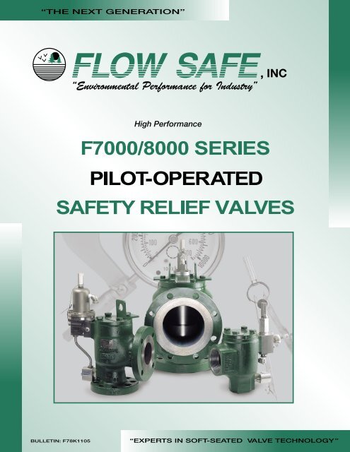
“THE NEXT GENERA TION”<br />
, INC<br />
High Performance<br />
BULLETIN: F78K1105<br />
“EXPERTS IN SOFT-SEATED VA L VE TECHNOLOGY”
2<br />
TABLE OF CONTENTS<br />
SECTION<br />
OVERVIEW<br />
CONSTRUCTIO N<br />
PAGES<br />
Operation . . . . . . . . . . . . . . . . . . . . . . . . . . . . . . . . 3<br />
Dimensions and W eights . . . . . . . . . . . . . . . . . . . . 4<br />
Inlet/Outlet Flange Ratings . . . . . . . . . . . . . . . . . . 5<br />
Seat and Seal Data . . . . . . . . . . . . . . . . . . . . . . . . . 5<br />
Main V alve Assembly and Constructio n. . . . . . 6-7<br />
F200 Snap Acting Pilot V alve Operation . . . . . . . 8<br />
F200 Snap Acting Pilot V alve Constructio n . . . . . 9<br />
F300 Modulating Pilot V alve Operation . . . . . . . 10<br />
F300 Modulating Pilot V alve Construction. . . . . 11<br />
F500 Modulating Pilot Valve Operation . . . . . . . 12<br />
F500 Modulating Pilot V alve Construction. . . . . 13<br />
Accessories and Options . . . . . . . . . . . . . . . . 14-15<br />
ENGINEERING DA TA<br />
Sizing: Gases and Liquids . . . . . . . . . . . . . . . . . . 16<br />
V iscosity Corr ection Factors<br />
. . . . . . . . . . . . . . . 17<br />
Sizing and Set Pr essur e Considerations<br />
for Backpr essure . . . . . . . . . . . . . . . . . . . . . . . . . 18<br />
Conversion Factors . . . . . . . . . . . . . . . . . . . . . . . 19<br />
Molecular W eights and C Factors . . . . . . . . . . . 20<br />
Air/Natural Gas Capacities . . . . . . . . . . . . . . 21-24<br />
W ater Capacities . . . . . . . . . . . . . . . . . . . . . . . . . 25<br />
Part Numbering . . . . . . . . . . . . . . . . . . . . . . . . . . 26<br />
Specification Sheet and Or der For m . . . . . . . . . 27<br />
The policy of FLOW SAFE and its authorized<br />
assemblers is a commitment to value thr ough:<br />
Envir onmentally Compatible Products<br />
Cost Ef ficient Design, with Minimal Parts<br />
Quality Products, Readily Available<br />
Flexibility to meet Unique Customer Needs<br />
“No Hassle” Service<br />
INTRODUCTION AND FEATURES<br />
Intr oduction<br />
T oday’ s industrial needs ar e being driven by r equir ements for<br />
high capacity , leak-tight safety re lief valves to r educe fugitive<br />
emissions and to save customer pr oduct. The FLOW SAFE<br />
F7000/8000 Series Pilot Operated Safety Relief Va lves, with<br />
accurate operational characteristics, ar e engineer ed to pr ovide<br />
superior performance for today’ s industries.<br />
Dir ect-mount pilot valves, minimizing<br />
potential leak paths.<br />
Modulating or snap-acting, with inter changeable<br />
pilot valves.<br />
Integral Module (IM) design available,<br />
completely eliminating pilot tubing.<br />
Superior main valve seating for ce, pr oportional<br />
to nameplate set pr essur e.<br />
Repeatable, leak-tight seating and r e-seating,<br />
due to soft seat design.<br />
Compact pr ofiles,for easier handling, installation<br />
and maintenance.<br />
Adjustable blowdown capability .<br />
Large capacities thr ough the full -bore nozzle (F7000)<br />
and a variety of r educed API orifice selections (F8000) .<br />
Superior flow capacities, independently (NB) verified.<br />
Full lift at set pr essur e upon demand.<br />
Easy convertability of orifice sizes, field adjustable.<br />
Integral exhaust with F300 and F500 pilot valve.<br />
Set pr essur es fr om 15 to 6000 psig.<br />
-423F to +525F temperatur e range.<br />
A variety of materials and end connections, 316SS<br />
trim standar d on carbon steel main valves.<br />
No metal-to-metal contact of piston to liner assembly.<br />
Top entry main valve for easy maintenance/inspection.<br />
Lifting lugs standar d on sizes 2x3 and larger .<br />
One-piece main valve casting with integral flanges.<br />
Backflow pr eventer and field test connection -<br />
standar d featur es.<br />
Adjustments ar e heavy duty stainless steel<br />
safety-wir ed and sealed.<br />
All valves bear ASME “UV” stamp, at 15 psig<br />
and above.<br />
Compliance with industry standar ds,<br />
including ASME, NACE, ANSI, and DOT .<br />
F7000/8000 SERIES
OPERATION<br />
System pr essur e is r outed fr om below the valve thr ough<br />
the pilot valve to the dome cavity of the main valve. This<br />
pr essur e, acting on a piston (dome) ar ea A d<br />
larger than<br />
the seat ar ea (A s<br />
), cr eates an ef fective downwar d for ce<br />
( F=Px( A d<br />
-A s<br />
)) holding the main valve piston down in<br />
the closed position.<br />
At the designated set pr essur e, the pilot valve<br />
r educes the dome pr essur e, pr oportional to demand<br />
if modulating (F300 or F500), or fully if snap-acting (F200),<br />
and allows the piston to go into lift. Once the system<br />
pr essur e is r elieved, the pilot valve closes at the pr eset<br />
blowdown, allowing the dome to r epr essurize and the<br />
main valve piston to close. When closed, dome pr essur e<br />
acting on a dif fer ential ar ea between the top and bottom<br />
of the piston assembly , cr eates a downwar d for ce on<br />
the seat pr oviding leak-tight shutof f.<br />
The F7000/8000 utilizes an elastomeric or plastic seat<br />
on the piston to achieve leak-tight seating. A dynamic<br />
piston seal pr events any leakage fr om the dome to the<br />
discharge. Wear rings on the piston eliminate metal-tometal<br />
contact with the liner and help to pr ovide smooth<br />
and consistent operation. Elastomeric/plastic seals seal<br />
the main valve and pilot valves.<br />
The F200 Snap-Acting pilot valve blowdown is set at<br />
5-7% of the set pr essur e and can be adjusted fr om 3%<br />
to 20% if so specified. The F300 and F500 modulating pilot<br />
valves pr ovide zer o blowdown, i.e. the main valve opens in<br />
pr oportion to demand and closes at the set pr essur e.<br />
The orifice size may be easily selected by choosing<br />
a full-bor e fixed inlet nozzle on the F7000, or by<br />
converting to a r educed size orifice (F8000) by<br />
attaching FLOW SAFE’ s unique annular-flow plug<br />
to the bottom of the piston assembly . This plug reduces<br />
the ef fective flow ar ea of the valve by directing the<br />
fluid between the plug O.D. and the nozzle I.D. This<br />
featur e in orifice selection allows the valve owner<br />
greater versatility in valve standar dization, utilization,<br />
and minimized inventor y.<br />
The F7000/8000 Series is particularly advantageous<br />
and cost-ef fective in installations wher e:<br />
Ther e may be size and weight limitations<br />
for the valve.<br />
A high cycling rate exists.<br />
A long service life is r equir ed.<br />
Minimal pr oduct loss is important .<br />
Reduced maintenance and installation<br />
time is desirable.<br />
3<br />
CLOSED<br />
OPEN<br />
OUTLET<br />
INLET<br />
F7000/8000 SERIES
DIMENSIONS AND WEIGHTS<br />
4<br />
F7000/8000 Series<br />
Flanged<br />
* With F300 Pilot Valve.,<br />
Deduct 2" (50 mm) for F200 Pilot Valve.<br />
Add 1/2" (13 mm) for F500 Pilot Valve<br />
thru Class 600 inlet.<br />
Add 4" (100 mm) for F500 Pilot Valve<br />
over Class 600 inlet.<br />
** See Page 5 for reduced<br />
orifice flow areas.<br />
B<br />
F7000/8000 Series<br />
Threaded<br />
B<br />
Available Available Dimensions, in (mm)<br />
Full Bore Reduced Inlet Outlet Approx.<br />
Orifice Orifice Flange Flange<br />
C weight,<br />
(F7000) (F8000)** A B approx.* lb (kg)<br />
.957" D, E, F 1" - 150# 2" - 150# 4.38 (111) 4.50 (114) 13.3 (338) 38 (17)<br />
2<br />
(0.719 in ) D, E, F 1" - 300# 2" - 150# 4.38 (111) 4.50 (114) 13.3 (338) 40 (18)<br />
2<br />
(4.64 cm ) D, E, F 1" - 600# 2" - 150# 4.38 (111) 4.50 (114) 13.3 (338) 40 (18)<br />
D, E, F 1" - 900# 2" - 300# 4.94 (126) 4.75 (121) 13.8 (351) 50 (23)<br />
.815" D, E, F 1" - 1500# 2" - 300# 4.94 (126) 4.75 (121) 13.8 (351) 50 (23)<br />
2 2<br />
(0.521 in ) (3.36 cm ) D, E 1" - 2500# 2" - 300# 4.94 (126) 4.75 (121) 13.8 (351) 50 (23)<br />
1.500" F, G, H 1-1/2" - 150# 3" - 150# 5.13 (130) 4.88 (124) 14.6 (371) 50 (23)<br />
2 2<br />
(1.767 in ) (11.40 cm ) F, G, H 1-1/2" - 300# 3" - 150# 5.13 (130) 4.88 (124) 14.6 (371) 55 (25)<br />
F, G, H 1-1/2" - 600# 3" - 150# 5.13 (130) 4.88 (124) 14.6 (371) 55 (25)<br />
1.337" F, G, H 1-1/2" - 900# 3" - 300# 6.38 (162) 6.75 (171) 15.1 (384) 80 (36)<br />
2 2<br />
(1.40 in ) (9.06 cm ) F, G, H 1-1/2" - 1500# 3" - 300# 6.38 (162) 6.75 (171) 15.1 (384) 80 (36)<br />
1.100" F, G, H 1-1/2" - 2500# 3" - 300# 6.38 (162) 6.75 (171) 15.1 (384) 90 (41)<br />
2 2<br />
(0.950 in ) (6.13 cm )<br />
1.939" G, H, J 2" - 150# 3" - 150# 5.38 (137) 4.88 (124) 15.8 (401) 65 (29)<br />
2<br />
(2.953 in ) G, H, J 2" - 300# 3" - 150# 5.38 (137) 4.88 (124) 15.8 (401) 70 (32)<br />
2<br />
(19.05 cm ) G, H, J 2" - 600# 3" - 150# 5.38 (137) 4.88 (124) 15.8 (401) 70 (32)<br />
1.689" G, H, J 2" - 900# 3" - 300# 6.56 (167) 6.75 (171) 17.0 (432) 90 (41)<br />
2 2<br />
(2.240 in ) (14.45 cm ) G, H, J 2" - 1500# 3" - 300# 6.56 (167) 6.75 (171) 17.0 (432) 90 (41)<br />
1.503" G, H, J 2" - 2500# 3" - 300# 7.00 (178) 6.75 (171) 17.4 (442) 115 (52)<br />
2 2<br />
(1.774 in ) (11.44 cm )<br />
2.900" J, K, L 3" - 150# 4" - 150# 6.13 (156) 6.38 (162) 18.3 (465) 90 (41)<br />
2<br />
(6.605 in ) J, K, L 3" - 300# 4" - 150# 6.38 (162) 6.38 (162) 18.5 (470) 100 (45)<br />
2<br />
(42.61 cm ) J, K, L 3" - 600# 4" - 150# 6.38 (162) 6.38 (162) 18.5 (470) 100 (45)<br />
2.624" J, K, L 3" - 900# 4" - 300# 7.50 (191) 7.13 (181) 19.6 (498) 130 (59)<br />
2 2<br />
(5.408 in ) (34.89 cm ) J, K, L 3" - 1500# 4" - 300# 7.50 (191) 7.13 (181) 19.6 (498) 145 (66)<br />
3.816" L, M, N, P 4" - 150# 6" - 150# 7.75 (197) 8.25 (210) 18.8 (478) 170 (77)<br />
2<br />
(11.437 in ) L, M, N, P 4" - 300# 6" - 150# 7.75 (197) 8.25 (210) 18.8 (478) 170 (77)<br />
2<br />
(73.79 cm ) L, M, N, P 4" - 600# 6" - 150# 7.75 (197) 8.25 (210) 18.8 (478) 175 (79)<br />
3.624" L, M, N, P 4" - 900# 6" - 300# 9.74 (247) 9.19 (233) 20.8 (528) 240 (109)<br />
2<br />
(10.315 in )<br />
2<br />
(66.55 cm )<br />
5.760"<br />
L, M, N, P<br />
Q, R<br />
4" - 1500#<br />
6" - 150#<br />
6" - 300#<br />
8" - 150#<br />
9.74 (247)<br />
9.44 (240)<br />
9.19 (233) 20.8 (528) 240 (109)<br />
9.50 (241) 22.8 (579) 270 (122)<br />
2<br />
(26.06 in ) Q, R 6" - 300# 8" - 150# 9.44 (240) 9.50 (241) 22.8 (579) 270 (122)<br />
2<br />
(168.1 cm ) Q, R 6" - 600# 8" - 150# 9.69 (246) 9.50 (241) 23.4 (594) 310 (141)<br />
7.625" T 8" - 150# 10" - 150# 10.88 (276) 11.00 (279) 26.5 (673) 460 (209)<br />
2<br />
(45.66 in ) T 8" - 300# 10" - 150# 10.88 (276) 11.00 (279) 26.5 (673) 460 (209)<br />
2<br />
(294.6 cm ) T 8" - 600# 10" - 150# 11.62 (295) 11.00 (279) 27.1 (688) 520 (236)<br />
11.935" W 12” - 150# 16” - 150# 11.92 (303) 15.56 (395) 32.0 (813) 1100 (500)<br />
2 2<br />
(111.87 in ) (721.7 cm )<br />
.957" D, E, F 1" FNPT 2" FNPT 5.06 (129) 3.00 (76) 14.0 (356) 35 (16)<br />
2 2<br />
(0.719 in ) (4.64 cm )<br />
1.500" F, G, H 1-1/2" FNPT 3" FNPT 4.63 (118) 3.75 (95) 14.1 (358) 45 (20)<br />
2 2<br />
(1.767 in ) (11.40 cm )<br />
F7000/8000 SERIES
F8000 ANNULAR<br />
FLOW PLUGS<br />
INLET/OUTLET FLANGE RATINGS<br />
Maximum Working Pressure, psig (barg)<br />
@ Temperature<br />
ASME<br />
-423 to -21°F -20 to 100°F 200°F 300°F 400°F 500°F<br />
essur<br />
g<br />
Class Material (-252 to -29°C) (-28 to 38°C) (93°C) (149°C) (204°C) (260°C)<br />
150# C. Steel Flange --- 290 (20) 260 (18) 230 (15) 200 (13) 170 (11)<br />
S. Steel Class 275 (19) M 275 (19 ) 235 (16) 215 (14) 195 300(13)<br />
400170 (11) 525<br />
300# C. Steel --- 750 (51) 750 (51) 730 (50) 705 (48) 665 (45)<br />
S. Steel 720 (49) 720 (49) 620 (42) 560 (38) 515 (35) 480 (33)<br />
600# * C. Steel --- 1500 (103) 1500 (103) 1455 (100) 1405 (97) 1330 (91)<br />
S. Steel 1440 (99) 1440 (99) 1240 (85) 1120 (77) 1025 (70) 955 (65)<br />
900# C. Steel --- 2250 (155) 2250 (155) 2185 (150) 2110 (145) 1995 (13)<br />
S. Steel 2160 (149) 2160 (149) 1860 (128) 1680 (115) 1540 (106) 1435 (99)<br />
1500# C. Steel --- 3750 (258) 3750 (258) 3640 (251) 3520 (242) 3325 (229)<br />
S. Steel 3600 (248) 3600 (248) 3095 (213) 2795 (192) 2570 (177) 2390 (164)<br />
2500# C. Steel --- 6000 (413) 6000 (413) 6000 (413) 5865 (404) 5540 (382)<br />
S. Steel 6000 (413) 6000 (413) 5160 (355) 4660 (321) 4280 (295) 3980 ( 274)<br />
Carbon steel: ASME SA-352 LCC Other materials available upon request.<br />
Stainless steel: ASME SA-351 CF3M<br />
Reference for pressure/temp. ratings: ASME B16.34 / B16.5<br />
* Includes 1 x 2 and 1-1/2 x 3 NPT<br />
Valve<br />
Size<br />
Orifice<br />
Size<br />
Flow Area,<br />
in 2 (cm 2 )<br />
1 x 2 D<br />
E<br />
F<br />
0.134 (0.86)<br />
0.235 (1.52)<br />
0.358 (2.31)<br />
1-1/2 x 3 F<br />
G<br />
H<br />
0.358 (2.31)<br />
0.588 (3.79)<br />
0.916 (5.91)<br />
2 x 3 G<br />
H<br />
J<br />
0.588 (3.79)<br />
0.916 (5.91)<br />
1.503 (9.70)<br />
3 x 4 J<br />
K<br />
L<br />
1.503 (9.70)<br />
2.147 (13.85)<br />
3.277 (21.14)<br />
4 x 6 L<br />
M<br />
N<br />
P<br />
3.277 (21.14)<br />
4.147 (26.75)<br />
5.014 (32.35)<br />
7.397 (47.72)<br />
6 x 8 Q<br />
R<br />
12.913 (83.31)<br />
18.704 (120.7)<br />
8 x 10 T 30.409 (196.2)<br />
12 x 16 W 78.81 (508.4)<br />
Teflon and Vespel and registered trademarks of the DuPont Company.<br />
Viton is a registered trademark of DuPont Performance Elastomers.<br />
SEAT AND SEAL DATA<br />
Continuous Process Min.<br />
Max.<br />
Temp.,<br />
o F ( o C ) Pressure, Pressure,<br />
Material Min. Max. psig (barg) psig(barg)<br />
Buna-N -30 (-34) 275 (135) 15 (1) 6000 (413)<br />
Viton® -30 (-34 ) 400 (204) 15 (1) 6000 (413)<br />
Ethylene Propylene -65 (-53) 325 (162) 15 (1) 6000 (413 )<br />
Polyurethane -60 (-51) 225 (107) 15 (1) 6000 (413)<br />
PTFE / Teflon® -423 (-252) 400 (204) 15 (1) 1000 (69)<br />
PCTFE /Kel-F -423 (-252) 400 (204) 1000 (69) 4000 (275)<br />
Vespel® -423 (-252) 500 (260) 4000 (275) 6000 ( 413)<br />
PEEK 0 (-1 7) 525 (273 4000 (275) 6000 (413)<br />
5<br />
F7000/8000 SERIES
MAIN VALVE CONSTRUCTION<br />
Part Name<br />
1 1,2<br />
Carbon Steel, -S1 (-N1 )<br />
1 1,2<br />
Stainless Steel, -SS (-NS )<br />
Body<br />
Liner<br />
Piston<br />
Retainer<br />
Annular Flow Plug (F8000 only)<br />
Retainer Bolt<br />
Piston Seal<br />
Backup Rings<br />
Wear / Wedge Ring<br />
Seat<br />
Field Test Conn. (FTC) Body<br />
FTC Piston, Connector, Plug<br />
Pickup Tube<br />
Lock Nut<br />
FTC Crush Ring<br />
FTC Seals<br />
Cap<br />
Lockwasher<br />
Cap Bolt<br />
Liner Seal<br />
Spool Piece (IM only)<br />
Spool Piece O-rings (IM only)<br />
Pilot Mounting Bolt<br />
Nameplate<br />
Locking Thread Insert<br />
Pipe Plug<br />
Dome Spring<br />
Lifting Bracket<br />
SA-352 LCC<br />
A743 CF8M<br />
A479 316 or A351 CF8M<br />
316 SS<br />
A479 316<br />
A193 B8 or B8M<br />
Elastomer 3 or PTFE 4<br />
PTFE<br />
Graphite-filled PTFE<br />
Elastomer or Plastic 3<br />
A479 316<br />
316 SS<br />
A479 316<br />
SS<br />
PTFE<br />
Elastomer 3<br />
SA-516 Gr. 70<br />
SS<br />
SA-193 B7<br />
Elastomer 3<br />
316 SS<br />
Elastomer 3<br />
304 SS<br />
SS or Aluminum<br />
304 SS (Inconel X750)<br />
CS<br />
302/304 SS (Inconel X750)<br />
A36<br />
SA-351 CF3M<br />
A743 CF8M<br />
A479 316 or A351 CF8M<br />
316 SS<br />
A479 316<br />
A193 B8 or B8M<br />
Elastomer 3 or PTFE 4<br />
PTFE<br />
Graphite-filled PTFE<br />
Elastomer or Plastic 3<br />
A479 316<br />
316 SS<br />
A479 316<br />
SS<br />
PTFE<br />
Elastomer 3<br />
SA-240 / SA-479 316<br />
SS<br />
SA-193 B8<br />
Elastomer 3<br />
316 SS<br />
Elastomer 3<br />
304 SS<br />
SS<br />
304 SS (Inconel X750)<br />
304 or 316 SS<br />
302/304 SS (Inconel X750)<br />
SS<br />
7<br />
1<br />
Part number material code – See Page 26<br />
2<br />
(Alternate materials) to meet NACE MR0175<br />
3<br />
See Page 5 for seat and seal selections Other materials<br />
4<br />
PTFE piston seals for F7040/8040 have 316 SS spring available upon request<br />
"IM"-STYLE<br />
PILOT<br />
(F300 SHOWN)<br />
BACKUP RING<br />
SPOOL PIECE<br />
O-RING<br />
F<br />
PILOT MOUNTING<br />
BOLTS<br />
SPOOL PIECE<br />
O-RING<br />
BACKUP RING<br />
SPOOL PIECE<br />
(PRESSURE ISOLATION SPOOL)<br />
Pilot<br />
Supply<br />
Ports<br />
FTC<br />
PISTON<br />
FTC<br />
CONNECTOR<br />
BACKUP RING<br />
SPOOL PIECE<br />
O-RING<br />
VENTED PLUG<br />
FTC<br />
SEAL<br />
SPOOL PIECE SEAL<br />
ARRANGEMENT<br />
FTC PISTON<br />
SEAL<br />
F7040 "IM" VALVE ASSEMBLY<br />
F7000/8000 SERIES
F200 SERIES PILOT VALVE OPERATION<br />
SPECIFICATIONS<br />
Style: Non-Flowing, Snap-Acting<br />
Service: Gas/Vapor<br />
Set Pressure Range: 15 – 6000 psig<br />
FEATURES<br />
FEATURES<br />
Direct Mount to Main Valve<br />
Built-in Backflow Preventer<br />
Adjustable Blowdown<br />
Variety of Materials Available<br />
Balanced against backpressure<br />
when vented to atmosphere<br />
Simple to Maintain<br />
Main Valve Full Lift at Set Point<br />
OPEN (RELIEVING)<br />
POSITION<br />
INLET PRESSURE<br />
ABOVE SET<br />
PRESSURE<br />
EXHAUST<br />
8<br />
CLOSED<br />
POSITION<br />
INLET PRESSURE<br />
BELOW SET<br />
PRESSURE<br />
INLET<br />
CLOSED<br />
POSITION<br />
INLET PRESSURE<br />
LOADING DOME<br />
THROUGH BFP<br />
DOME<br />
FILL<br />
CLOSED<br />
POSITION<br />
EXHAUST PRESSURE<br />
LOADING DOME<br />
THROUGH BFP<br />
INLET<br />
DOME<br />
FILL<br />
DOME<br />
FILL<br />
INLET<br />
FEED<br />
INLET<br />
BACKFLOW<br />
PREVENTER<br />
(BFP)<br />
INLET<br />
EXHAUST<br />
BACKPRESSURE<br />
F7000/8000 SERIES
1<br />
9<br />
F7000/8000 SERIES
SPECIFICATIONS<br />
FEATURES<br />
10<br />
F7000/8000 SERIES
Part Name<br />
Body<br />
Internal Plug<br />
Lower Piston<br />
Sleeve<br />
Seals, O-rings<br />
Seat<br />
Backup Rings<br />
Spacer Pin<br />
Seat Retainer Nozzle<br />
Upper Piston<br />
Diaphragm Fastener<br />
Diaph. Support Disc<br />
Diaph. Support Ring<br />
Diaphragm Disc<br />
Diaph. Area Reducer<br />
Adapter<br />
Spring Washer<br />
Spring<br />
Bonnet<br />
Bolt<br />
Diaphragm<br />
Lock Nuts<br />
PA Screw<br />
Cap<br />
BFP Nozzle<br />
BFP Piston<br />
BFP Seal<br />
BFP Jam Nut<br />
Prop. Band Screw<br />
Prop. B. S. Seal<br />
Pipe Plugs<br />
Inlet Screen<br />
Vent/Bug Screen<br />
Lockwire<br />
Standard Mat'ls<br />
SA-479 316<br />
A479 316<br />
A479 316<br />
A479 316<br />
Elastomer 1<br />
Elastomer 1<br />
Teflon / PTFE<br />
A479 316<br />
A479 316<br />
A479 316<br />
A479 316<br />
A479 316<br />
A479 316<br />
A479 316<br />
A479 316<br />
A479 316<br />
A479 316<br />
302/304/17-7 SS<br />
A351 CF8M<br />
304 or 13-8 SS<br />
Elastomer 2<br />
SS<br />
A479 316<br />
A479 316<br />
A479 316<br />
A479 316<br />
Teflon / PTFE<br />
304 or 316 SS<br />
A479 316<br />
Teflon / PTFE<br />
304 or 316 SS<br />
316 SS<br />
304 or 316 SS<br />
SS<br />
1<br />
See Page 5 for seat and seal selections<br />
2<br />
Available in Buna-N, Viton, EPDM, Teflon/FEP<br />
Standard materials meet NACE MR0175<br />
1<br />
BOLT<br />
DIAPHRAGM<br />
VENT/<br />
BUG SCREEN<br />
DIAPHRAGM<br />
FASTENER SEAL<br />
SEAT<br />
SMALL<br />
FACE SEAL<br />
UPPER<br />
SLEEVE SEAL<br />
LOWER<br />
SLEEVE SEAL<br />
SLEEVE<br />
SPACER PIN<br />
LARGE<br />
FACE SEAL<br />
ADAPTER SEAL<br />
F300 SERIES PILOT VALVE CONSTRUCTION<br />
PIPE<br />
PLUG<br />
DIAPHRAGM<br />
AREA REDUCER<br />
CAP<br />
LOCK NUT<br />
BONNET<br />
BODY<br />
A<br />
A<br />
LOWER<br />
PISTON<br />
LOWER<br />
PISTON SEAL<br />
INTERNAL<br />
PLUG<br />
LP DIAPHRAGM STYLE (TO 285 PSIG)<br />
DIAPHRAGM DISC<br />
HP DIAPHRAGM STYLE<br />
(OVER 285 TO 500 PSIG)<br />
PA SCREW<br />
SPRING WASHER<br />
F<br />
LOCKWIRE<br />
SPRING<br />
DIAPHRAGM<br />
FASTENER<br />
DIAPHRAGM<br />
SUPPORT DISC<br />
DIAPH. SUPPORT<br />
RING SEAL<br />
DIAPHRAGM<br />
SUPPORT RING<br />
LEAD SEAL<br />
UPPER PISTON SEAL<br />
UPPER PISTON<br />
SEAT RETAINER NOZZLE<br />
PROPORTIONAL<br />
BAND SCREW<br />
LOCK NUT<br />
PROP. BAND<br />
SCREW SEAL<br />
PIPE PLUG<br />
INLET SCREEN<br />
PLUG SEAL<br />
ADAPTER<br />
11<br />
PIPE<br />
PLUG<br />
BFP NOZZLE<br />
BFP JAM NUT<br />
BACKUP RING<br />
UPPER PISTON SEAL<br />
BACKUP RING<br />
UPPER PISTON<br />
BFP PISTON<br />
BFP O-RING<br />
BFP SEAL<br />
BACKFLOW PREVENTER (BFP)<br />
SECTION A-A<br />
PISTON STYLE (OVER 500 - 6000 PSIG)<br />
F7000/8000 SERIES
F500 SERIES PILOT VALVE OPERATION<br />
SPECIFICATIONS<br />
Style: Modulating (Non-Flowing), Balanced<br />
Service: Gas/Vapor/Liquid<br />
Set Pressure Range:<br />
Diaphram Style: 15 – 285 psig<br />
Piston Style: 285 – 6000 psig<br />
FEATURES<br />
FEATURES<br />
Direct Mount to Main Valve w/Integral Exhaust<br />
Non-Flowing<br />
Opens in Proportion to Upset<br />
Balanced against Backpressure,<br />
with Built-in Backflow Preventer<br />
Optional Set Point Indicator Button Available<br />
Variety of Materials Available<br />
OPEN (RELIEVING)<br />
POSITION<br />
INLET PRESSURE<br />
ABOVE SET<br />
PRESSURE<br />
DOME<br />
DISCHARGE<br />
12<br />
INLET<br />
PILOT VALVE<br />
EXHAUST<br />
Backflow Preventer (BFP)<br />
operation same as for F300 Pilot<br />
(see Page 10).<br />
DOME<br />
FILL<br />
CLOSED POSITION<br />
INLET PRESSURE<br />
BELOW SET PRESSURE<br />
INLET<br />
F7000/8000 SERIES
ACCESSORIES AND OPTIONS<br />
Backflow Preventer (Standard Feature)<br />
If outlet pressure exceeds the inlet pressure, the main valve can<br />
open and backfow may occur. To prevent backflow, a standard<br />
backflow preventer is incorporated in the F200, F300, and<br />
F500 pilots. An increase in the outlet pressure above the inlet is<br />
transmitted to the top of the main valve piston, thus keeping<br />
the main valve closed and protecting the vessel from exposure<br />
to backpressure and backflow contamination.<br />
DOME<br />
COMMUNICATION<br />
PORT<br />
INLET FEED<br />
EXHAUST<br />
BACKPRESSURE<br />
INLET<br />
14<br />
CLOSED WITH BACKPRESSURE<br />
GREATER THAN INLET PRESSURE<br />
INLET<br />
CLOSED WITH INLET PRESSURE APPLIED<br />
Manual/Remote Blowdown<br />
This allows the main valve to lift without opening the pilot valve,<br />
by discharging the piston dome pressure directly to the<br />
atmosphere. This is accomplished by use of a manual or<br />
automatic blowdown valve, e.g. hand valve or solenoid valve.<br />
MANUAL<br />
VALVE<br />
F7000/8000 SERIES
F<br />
ACCESSORIES AND OPTIONS<br />
Field Test Connection (FTC)<br />
This allows the user to verify the set pressure while<br />
in service without valve removal. An external pressure<br />
source is attached to the FTC to direct pressure<br />
to the pilot valve, while blocking off the inlet pressure,<br />
thus checking the set pressure and the general<br />
operation of the valve.<br />
Inlet Supply Filter<br />
A filter should be used for dirty applications to clean<br />
the supply fluid to the pilot valve. This is supplied<br />
with a drain fitting.<br />
15<br />
"IM"<br />
CONSTRUCTION<br />
Remote Pressure Pickup<br />
Remote pressure pickup is recommended when<br />
inlet piping pressure losses exceed 3% of relief valve<br />
set pressure. This allows a remote, more direct<br />
pressure sensing to the pilot valve.<br />
F7000/8000 SERIES
SIZING: GASES AND LIQUIDS<br />
16<br />
REF: API RP 520, Part 1<br />
Gases<br />
To size for gases, use the formulas below.<br />
To select the proper orifice for the particular service<br />
conditions, the following information is required:<br />
1. Required flow capacity<br />
2. Required set pressure<br />
3. Operating Pressure – to assure that it is below<br />
the reseat pressure<br />
4. Overpressure (10% Maximum)<br />
5. Molecular Weight/Gas Constant of Media<br />
6. Process Temperature<br />
Gases or Vapors<br />
(US units)<br />
A =<br />
V<br />
MTZ<br />
6.32 CKK b<br />
K c<br />
P 1<br />
- OR - - OR -<br />
A = W<br />
2<br />
TZ<br />
131.6W<br />
A = Required Valve Orifice Area (in 2 or cm )<br />
A<br />
CKK b<br />
K c<br />
P TZ<br />
1 M<br />
CKK b<br />
K c<br />
P 1 M<br />
Q = Required Flow Rate (gpm or lpm)<br />
G = Specific Gravity of Liquid<br />
A = Required Valve Orifice Area (in 2 2<br />
or cm )<br />
K = Certified (Derated) Coefficient of Discharge<br />
3<br />
V = Required Flow Capacity (scfm or Nm /min)<br />
(see chart below)<br />
W = Required Flow Capacity (lb/hr or kg/hr)<br />
K c<br />
= 0.9 with rupture disk upstream of relief valve;<br />
= 1.0 with no rupture disk<br />
K = Certified (Derated) Coefficient of Discharge<br />
(see chart below)<br />
K v<br />
= Viscosity Correction Factor (see Page 17)<br />
P 1<br />
= Pressure at Valve Inlet During Flow (psia or kPaa) P 1<br />
= Pressure at Valve Inlet During Flow (psig or kPag)<br />
= Set Pressure + Overpressure + P atm<br />
= Set Pressure + Overpressure<br />
P atm<br />
= Atmospheric Pressure<br />
14.7 psia or 101.3 kPaa if unknown<br />
P 2<br />
= Backpressure (psig or kPag)<br />
C = Gas Constant<br />
M = Molecular Weight of Flowing Media<br />
T = Inlet Temperature, Absolute<br />
R = (F + 460) or K = (C + 273)<br />
DISCHARGE COEFFICIENTS (K)<br />
Z = Compressibility Factor<br />
if Unknown, Z = 1.0<br />
F7000 F8000<br />
K b<br />
= Backpressure Correction Factor -<br />
See page 18 for subcritical flow;<br />
use 1.0 for critical flow<br />
K c<br />
= 0.9 with rupture disk upstream of relief valve;<br />
= 1.0 with no rupture disk<br />
Liquids<br />
To size for liquids, use the formulas below.<br />
To select the proper orifice for the particular service<br />
conditions, the following information is required:<br />
1. Required flow capacity<br />
2. Required set pressure<br />
3. Operating Pressure – to assure that it is below<br />
the reseat pressure<br />
4. Acceptable Overpressure (10% Maximum)<br />
5. Specific Gravity of the Liquid<br />
6. Backpressure<br />
(SI units) (US units) (SI units)<br />
352.5V MTZ<br />
Q G<br />
11.78Q G<br />
A = A = A<br />
CKK =<br />
b<br />
K c<br />
P 1 38 KK c<br />
K v<br />
P 1<br />
- P 2<br />
KK c<br />
K v<br />
P 1<br />
- P 2<br />
Gas .824 .878<br />
*Liquid .634 --<br />
*F300 & F500 modulating pilots only<br />
F7000/8000 SERIES
SIZING FOR VISCOUS FLUIDS<br />
R =<br />
Viscosity Correction,<br />
per API RP520<br />
When sizing a valve for viscous liquid service,<br />
first size the valve for non-viscous conditions,<br />
to determine a preliminary required orifice area.<br />
Select the next larger orifice and then use that<br />
area in determining the Reynold’s number (R).<br />
The formulas below can be used to determine R.<br />
(US units)<br />
Q x (2800) x G<br />
C p<br />
x<br />
A<br />
– OR –<br />
12700 x Q<br />
R = SSU x A<br />
R =<br />
(SI units)<br />
Q x (1880) x G<br />
C p<br />
x<br />
A<br />
– OR –<br />
8522 x Q<br />
R = SSU x A<br />
2 2<br />
A = Effective (selected) discharge area (in or cm )<br />
Q<br />
G<br />
C p<br />
= Required flowrate at the flowing temperature<br />
(gpm or lpm).<br />
= Specific gravity of the liquid at the<br />
flowing temperature. Water: G = 1.0<br />
= Absolute viscosity at the flowing temperature,<br />
in centipoise.<br />
SSU = Viscosity at the flowing temperature,<br />
in Saybolt Seconds Universal.<br />
After the value of R is determined, K v<br />
is obtained from<br />
the chart below. K v<br />
is then applied to correct the<br />
“preliminary required flow area”. If the corrected area<br />
exceeds the chosen standard orifice area, repeat the<br />
above procedure using the next larger orifice size.<br />
Minimum and maximum conditions should be<br />
considered when determining the required orifice size,<br />
for proper pilot valve operation.<br />
17<br />
F7000/8000 SERIES
SIZING AND SET PRESSURE CONSIDERATIONS FOR BACKPRESSURE<br />
18<br />
Constant Backpr essur e Sizing Factor (K b<br />
)<br />
(Gases & V apors Only)<br />
In general, backpr essur e has no ef fect on the flow<br />
capacity of the FLOW SAFE F7000/8000 Series of pilo t-<br />
operated valves as long as a critical flow condition exists.<br />
The critical flow pr essur e ratio for a particular gas may be<br />
estimated per API RP 520 by the equation below:<br />
P cf<br />
[<br />
2<br />
]<br />
=<br />
P 1<br />
K + 1<br />
k /(k-1)<br />
k = Specific heat ratio for gas, C p /C v<br />
(see page 20)<br />
P 1<br />
= Upstr eam relieving pr essur e (psia)<br />
P cf<br />
= Critical flow nozzle pr essur e (psia)<br />
P B<br />
= Backpr essur e, psi a<br />
P s<br />
= Set pr essur e, psi a<br />
P o<br />
= O verpr essur e, psi<br />
W hen suf ficient back pr essur e exists to cr eate<br />
a subcritical flow condition, the critical sizing equatio n<br />
shown on Page 16 should be used along with the Backpr<br />
essur e Sizing Factor (K b<br />
) shown in the chart below .<br />
This method is described in detail in API RP520.<br />
Set pr essur es ar e not af f ected by backpr essur e when<br />
using the F300 or F500 pilot valve as it is balanced against<br />
such pr essur e, or the F200 as it is normally vented to<br />
atmosphe re . Caution should be used if the F200 vent is<br />
r outed to the main valve discharge or other pr essurized<br />
vessel, as the set pr essur e and blowdown may be<br />
af fected.<br />
Backpr essur e gr eater than the system inlet pr essur e<br />
normally would cause the main valve piston to open.<br />
Because the F200, F300, and F500 pilot valves ar e equipped<br />
w ith backflow pr eventers as standar d featur es, this<br />
cannot occur on the F7000/8000 valves. The<br />
backpr essur e is r outed to the main valve piston<br />
dome, keeping the valve closed and bubble-tight .<br />
Example: See figur e below .<br />
S et Pr essur e = 100 psig<br />
Overpr essur e = 10 psi<br />
Superimposed backpr essur e = 70 psi g<br />
Built-up backpr essur e = 10 ps ig<br />
Per cent absolute<br />
backpressure =<br />
K b<br />
= 0.87(for k=1.4)<br />
70+10+14. 7<br />
100+10+14. 7<br />
x 100 = 76%<br />
F7000/8000 SERIES
EQUIVALENTS AND CONVERSION FACTORS<br />
This table may be used two ways:<br />
1. Multiply the unit under column A by the figure under<br />
column B, to obtain the unit under column C.<br />
2. Divide the unit under column C by the figure under<br />
column B; the result is then the unit under column A.<br />
Multiply By To Obtain<br />
A B C<br />
Atmospheres 14.697 Pounds / sq. in.<br />
Atmospheres 1.033 Kilograms / sq. cm.<br />
Atmospheres 29.92 Inches of mercury<br />
Atmospheres 760. Millimeters of mercury<br />
Atmospheres 407.1 Inches of water<br />
Atmospheres 33.90 Feet of water<br />
Atmospheres 1.013 Bars<br />
Atmospheres 101.326 KiloPascals<br />
Barrels 42. Gallons (U.S.)<br />
Bars 14.5 Pounds / sq. in.<br />
Bars 1.02 Kilograms / sq. cm.<br />
Bars 100.0 KiloPascals<br />
Centimeters 0.3937 Inches<br />
Centimeters 0.03281 Feet<br />
Centimeters 0.01 Meters<br />
Centimeters 0.01094 Yards<br />
Cubic centimeters 0.06102 Cubic inches<br />
Cubic feet 7.48055 Gallons<br />
Cubic feet 0.17812 Barrels<br />
Cubic ft. / minute .02831 Cubic meters / minute<br />
Cubic ft. / second 448.833 Gallons / minute<br />
Cubic inches 16.39 Cubic centimeters<br />
Cubic inches 0.004329 Gallons<br />
Cubic meters 264.17 Gallons<br />
Cubic meters / hour 4.4 Gallons / minute<br />
Cubic meters / minute 35.32 Cubic ft./ minute<br />
Feet 0.3048 Meters<br />
Feet 0.3333 Yards<br />
Feet 30.48 Centimeters<br />
Feet of water 0.882 Inches of mercury<br />
Feet of water 0.433 Pounds / sq. in.<br />
Gallons (U.S.) 3785. Cubic centimeters<br />
Gallons (U.S.) 0.13368 Cubic feet<br />
Gallons (U.S.) 231. Cubic inches<br />
Gallons (Imperial) 277.4 Cubic inches<br />
Gallons (U.S.) 0.833 Gallons (Imperial)<br />
Gallons (U.S.) 3.785 Liters<br />
Gallons of water 8.328 Pounds (at 21°C)<br />
Gallons of liquid<br />
Pounds / hour liquid<br />
/ minute 550 x Sp. Gr. (at 21°C)<br />
Gallons / minute 0.002228 Cubic ft / second<br />
Grams .035 Ounces<br />
Inches 2.54 Centimeters<br />
Inches 0.0833 Feet<br />
Inches 0.0254 Meters<br />
Multiply By To Obtain<br />
A B C<br />
Inches 0.02778 Yards<br />
Inches of mercury 1.133 Feet of water<br />
Inches of mercury 0.4912 Pounds / sq. in.<br />
Inches of mercury 0.0334 Atmospheres<br />
Inches of mercury 0.0345 Kilograms / sq. cm.<br />
Inches of water 0.03613 Pounds / sq. in.<br />
Inches of water 0.07355 Inches of mercury<br />
Kilograms 2.205 Pounds<br />
Kilograms 0.001102 Short tons (2000 lbs)<br />
Kilograms 35.27 Ounces<br />
Kilograms .2646 Gallons (U.S.)<br />
Kilograms / minute 132.3<br />
H 2O @ 70F<br />
Pounds / hour<br />
Kilograms / sq. cm. 14.22 Pounds / sq. in.<br />
Kilograms / sq. cm. 0.9678 Atmospheres<br />
Kilograms / sq. cm. 28.96 Inches of mercury<br />
KiloPascals .145 Pounds / sq. in.<br />
KiloPascals .01 Bars<br />
KiloPascals .0102 Kilograms / sq. cm.<br />
Liters .035 Cubic feet<br />
Liters 1000. Cubic centimeters<br />
Liters 0.2642 Gallons<br />
Liters / hour 0.0044 gallons / minute<br />
Meters 3.281 Feet<br />
Meters 1.0936 Yards<br />
Meters 100. Centimeters<br />
Meters 39.37 Inches<br />
Pounds .1198 H2O @ 70F<br />
Gallons (U.S.)<br />
Pounds 453.6 Grams<br />
Pounds 0.0005 Short tons (2000 lbs)<br />
Pounds 0.4536 Kilograms<br />
Pounds 0.000454 Metric tons<br />
Pounds 16. Ounces<br />
Pounds / hour 6.32/M.W. Cubic ft. / minute<br />
Pounds / hour liquid 0.002/Sp.Gr. Gallons / minute liquid<br />
(at 21C )<br />
Pounds / sq. in. 27.703 Inches of water<br />
Pounds / sq. in. 2.308 Feet of water<br />
Pounds / sq. in. 2.036 Inches of mercury<br />
Pounds / sq. in. 0.0703 Kilograms / sq. in.<br />
Pounds / sq. in. 0.0680 Atmospheres<br />
Pounds / sq. in. 51.71 Millimeters of mercury<br />
Pounds / sq. in. 0.7037 Meters of water<br />
Specific gravity 28.97 Molecular Wt.<br />
(of gas or vapors)<br />
(of gas or vapors)<br />
Square centimeters 0.1550 Square inches<br />
Square Inches 6.452 Square centimeters<br />
Water (cubic feet) 62.3 Pounds (at 21C )<br />
Temperature<br />
Celsius = 5/9 (Fahrenheit – 32)<br />
Fahrenheit = 9/5 (Celsius) + 32<br />
19<br />
F7000/8000 SERIES
ENGINEERING DATA<br />
Molecular Weights and “C” Factors<br />
Listed below are the molecular weights, specific heat<br />
ratios, and “C” factors for common gases. This “C”<br />
factor is used in formulas for sizing valves for<br />
gas or vapor service.<br />
On the following pages are published capacity charts<br />
for two common gases, air and natural gas, and for<br />
water. These charts can be used for direct selection<br />
of the safety relief valve orifice required without<br />
calculations. Capacities in these charts are based<br />
upon a process media temperature of 60F , and a<br />
compressibility factor (Z) = 1.0. To determine capacities<br />
at other temperatures, further calculations should be<br />
made using the formulas on Page 16.<br />
20<br />
Specific<br />
Heat Ratio<br />
Gas Mol. Wt (Cp/Cv) C<br />
Acetylene - C 2<br />
H 2<br />
26 1.28 345<br />
Air 29 1.40 356<br />
Ammonia - NH 3<br />
17 1.31 348<br />
Argon - Ar 40 1.66 377<br />
Benzene - C 6<br />
H 6<br />
78 1.10 327<br />
Carbon Disulphide - CS 2<br />
76 1.21 338<br />
Carbon Dioxide - CO 2<br />
44 1.29 346<br />
Carbon Monoxide - CO 28 1.40 356<br />
Chlorine - Cl 2<br />
71 1.36 352<br />
Cyclohexane 84 1.08 324<br />
Ethane - C 2<br />
H 6<br />
30 1.19 336<br />
Ethylene - C 2<br />
H 4<br />
28 1.24 341<br />
Freon 22 86.5 1.18 335<br />
Helium - He 4 1.66 377<br />
Hexane - C 6<br />
H 14<br />
86 1.08 324<br />
Hydrochloric Acid - HCl 36.5 1.40 356<br />
Hydrogen - H 2<br />
2 1.41 357<br />
Hydrogen Sulfide - H 2<br />
S 34 1.32 348<br />
Iso Butane 58 1.11 328<br />
Methane - CH 4<br />
16 1.31 348<br />
Methyl Alcohol - CH 3<br />
OH 32 1.20 337<br />
Methyl Chloride - CH 3<br />
Cl 50.5 1.20 337<br />
Methyl Mercaptan - CH 4<br />
S 48.1 1.20 337<br />
N-Butane - C 4<br />
H 10<br />
58 1.11 328<br />
Natural Gas 19 1.27 345<br />
Nitrogen - N 2<br />
28 1.40 356<br />
Oxygen - O 2<br />
32 1.40 356<br />
Pentane - C 5<br />
H 12<br />
72 1.09 325<br />
Propane - C 3<br />
H 8<br />
44 1.13 330<br />
Propylene - C 3<br />
H 6<br />
42 1.15 332<br />
Sulphur Dioxide - SO 2<br />
64 1.28 345<br />
Water Vapor/Steam 18 1.30 347<br />
Specific<br />
Specific<br />
Heat Ratio<br />
Heat Ratio<br />
(Cp/Cv) C (Cp/Cv) C<br />
1.00 315 1.52 366<br />
1.02 318 1.54 368<br />
1.04 320 1.56 369<br />
1.06 322 1.58 371<br />
1.08 324 1.60 372<br />
1.10 327 1.62 374<br />
1.12 329 1.64 376<br />
1.14 331 1.66 377<br />
1.16 333 1.68 379<br />
1.18 335 1.70 380<br />
1.20 337 1.72 382<br />
1.22 339 1.74 383<br />
1.24 341 1.76 384<br />
1.26 343 1.78 386<br />
1.28 345 1.80 387<br />
1.30 347 1.82 388<br />
1.32 349 1.84 390<br />
1.34 351 1.86 391<br />
1.36 352 1.88 392<br />
1.38 354 1.90 394<br />
1.40 356 1.92 395<br />
1.42 358 1.94 397<br />
1.44 359 1.96 398<br />
1.46 361 1.98 399<br />
1.48 363 2.00 400<br />
1.50 365 2.20 412<br />
F7000/8000 SERIES
F7000 GAS FLOW CAPACITIES<br />
10% / 3 psi Overpressure, 60 degF, Z=1.0, MW=29<br />
VA L VE SIZE 1 x 2 1-1/2x3 2x3 3x4 4x6 6x8 8x10 12x16<br />
ORIFICE AREA(in 2 ) 0.719 1.767 2.953 6.605 11.437 26.06 45.66 111.87<br />
K 0.824 0.824 0.824 0.824 0.824 0.824 0.824 0.824<br />
AIR<br />
Set Pr essur e<br />
(psig) SCFM SCFM SCFM SCFM SCFM SCFM SCFM SCFM<br />
15 355 872 1458 3261 5646 12865 22541 55227<br />
20 409 1006 1681 3759 6509 14832 25988 63672<br />
25 464 1139 1904 4258 7373 16799 29435 72117<br />
30 518 1272 2127 4756 8236 18767 32881 80561<br />
40 637 1566 2617 5853 10135 23094 40464 99139<br />
50 757 1859 3107 6950 12035 27422 48047 117717<br />
75 1055 2593 4333 9692 16783 38241 67003 164162<br />
100 1354 3327 5559 12435 21531 49061 85960 210607<br />
150 1951 4794 8011 17919 31028 70699 123873 303498<br />
200 2548 6261 10463 23403 40525 92338 161787 396388<br />
250 3145 7728 12915 28888 50021 113977 199700 489278<br />
285 3563 8755 14632 32727 56669 129124 226239 554301<br />
290 3622 8902 14877 33275 57618 131288 230031 563590<br />
300 3742 9195 15367 34372 59518 135615 237613<br />
400 4936 12130 20271 45341 78511 178893 313440<br />
500 6130 15064 25175 56310 97504 222170 389267<br />
600 7324 17999 30079 67279 116497 265448 465093<br />
700 8518 20933 34983 78247 135491 308725 540920<br />
740 8995 22107 36945 82635 143088 326036 571251<br />
750 9115 22400 37435 83732 144987 330364 578834<br />
800 9712 23868 39887 89216 154484 352002 616747<br />
900 10906 26802 44791 100185 173477 395280 692574<br />
1000 12100 29736 49695 111 154 192470 438557 768400<br />
1100 13294 32671 54599 122123 211464 481834 844227<br />
1200 14488 35605 59503 133091 230457 525112 920054<br />
1300 15682 38540 64407 144060 249450 568389 995880<br />
1400 16876 41474 69311 155029 268443 611666 1071707<br />
1480 17831 43822 73234 163804 283638 646288 1132369<br />
1500 18070 44409 74215 165998 287436 654944 1147534<br />
ORIFICE AREA 0.719 1.404 2.240 5.408 10.315<br />
1500 18070 35286 56296 135915 259238<br />
2000 24040 46944 74896 180819 344888<br />
2220 26667 52073 83079 200578 382574<br />
2250 27025 52773 84195 203272 387713<br />
ORIFICE AREA 0.521 1.404 2.240 5.408 10.315<br />
2300 20016 53938 86055 207762 396278<br />
2600 22611 60933 97215 234705 447667<br />
2900 25207 67928 108375 261648 499057<br />
3200 27803 74923 119535 288591 550447<br />
3500 30398 81917 130695 315534 601837<br />
3705 32172 86697 138320 333945 636953<br />
3750 32561 87746 139994 337986 644661<br />
ORIFICE AREA 0.521 0.950 1.774<br />
3800 32994 60161 112344<br />
4000 34724 63317 118236<br />
3<br />
Nm /hr = scfm<br />
4500 39050 71205 132966<br />
0.6218<br />
5000 43376 79093 147696<br />
5500 47702 86981 162426<br />
lb/hr air = 4.59 x (scfm)<br />
6000 52029 94870 177157<br />
21<br />
F7000/8000 SERIES
22<br />
AIR<br />
ORIFICE SIZE<br />
ORIFICE AREA (in 2)<br />
K<br />
Set Pressure<br />
(psig)<br />
D<br />
0.134<br />
0.878<br />
E<br />
0.235<br />
0.878<br />
F G H J K L<br />
0.588 0.916 1.503 2.147<br />
0.878 0.878 0.878 0.878<br />
0.358<br />
0.878<br />
SCFM SCFM SCFM SCFM SCFM SCFM SCFM SCFM SCFM SCFM SCFM SCFM SCFM SCFM SCFM<br />
15 70 124 188 309 482 791 1129 1724 2181 2638 3891 6793 9839<br />
20 81 143 217 357 556 912 1302 1987 2515 3041 4486 7831 11343<br />
25 92 161 246 404 629 1032 1475 2251 2849 3444 5081 8870 12848<br />
30 103 180 275 451 703 1153 1647 2515 3182 3847 5676 9908 14352<br />
40 127 222 338 555 865 1419 2027 3094 3916 4735 6985 12193 17662<br />
50 150 263 401 659 1027 1685 2407 3674 4650 5622 8294 14478 20971<br />
75 210 367 560 919 1432 2350 3357 5124 6484 7840 11566 20191 29246<br />
100 269 471 718 1180 1837 3015 4307 6574 8319 10058 14838 25903 37520<br />
150 387 679 1035 1700 2648 4345 6206 9473 11988 14494 21383 37328 54068<br />
200 506 887 1352 2220 3458 5675 8106 12372 15657 18930 27927 48753 70617<br />
250 624 1095 1668 2740 4269 7004 10006 15272 19326 23367 34472 60178 87165<br />
285 707 1241 1890 3104 4836 7935 11335 17301 21894 26472 39053 68175 98749<br />
300 743 1303 1985 3260 5079 8334 11905 18171 22995 27803 41016 71603 103714 168618<br />
400 980 1719 2619 4301 6700 10994 15704 23970 30333 36675 54106 94452 136811 222427<br />
500 1217 2135 3252 5341 8321 13653 19503 29768 37671 45547 67195 117302 169908 276236<br />
600 1454 2551 3886 6382 9942 16313 23303 35567 45010 54420 80284 140152 203005 330045<br />
700 1691 2966 4519 7422 11563 18972 27102 41366 52348 63292 93373 163002 236102 383855<br />
740 1786 3133 4772 7839 12211 20036 28621 43685 55283 66841 98608 172141 249340 405378<br />
750 1810 3174 4836 7943 12373 20302 29001 44265 56017 67728 99917 174426 252650 410759<br />
800 1929 3382 5153 8463 13184 21632 30901 47164 59686 72164 106462 185851 269199 437664<br />
900 2166 3798 5786 9503 14804 24292 34700 52963 67024 81037 119551 208701 302296 491473<br />
1000 2403 4214 6420 10544 16425 26951 38499 58762 74362 89909 132640 231551 335393 545282<br />
1100 2640 4630 7053 11584 18046 29611 42298 64561 81700 98781 145729 254400 368490 599091<br />
1200 2877 5046 7686 12625 19667 32270 46097 70359 89039 107654 158818 277250 401586 652900<br />
1300 3114 5461 8320 13665 21288 34930 49897 76158 96377 116526 171907 300100 434683 706709<br />
1400 3351 5877 8953 14706 22909 37589 53696 81957 103715 125398 184996 322950 467780 760518<br />
1480 3541 6210 9460 15538 24206 39717 56735 86596 109586 132496 195468 341229 494258 803566<br />
1500 3588 6293 9587 15746 24530 40249 57495 87755 111053 134271 198085 345799 500877 814327<br />
2000 4774 8372 12754 20949 32634 53547 76491 116749 147744 178632 263531<br />
2220 5296 9287 14148 23238 36200 59398 84849 129506 163888 198152 292327<br />
2250 5367 9412 14338 23550 36686 60196 85988 131245 166089 200813 296254<br />
2300 5485 9620 14655 24070 37497 61526 87888 134145 169759 205249 302798<br />
2600 6197 10867 16555 27191 42359 69504 99285 151541 191773 231866 342065<br />
2900 6908 12115 18456 30313 47222 77483 110683 168937 213788 258483 381333<br />
3200 7619 13362 20356 33434 52085 85462 122080 186333 235802 285100 420600<br />
3500 8331 14610 22257 36556 56947 93441 133478 203729 257817 311717 459867<br />
3705 8817 15462 23555 38689 60270 98893 141266 215616 272860 329906 486700<br />
3750 8923 15649 23840 39157 60999 100090 142976 218226 276162 333898 492590<br />
3800 9042 15857 24157 39677 61810 101419<br />
4000 9516 16689 25424 41758 65052 106739<br />
4500 10702 18768 28592 46960 73156 120036<br />
5000 11887 20847 31759 52163 81260 133334<br />
5500 13073 22927 34926 57365 89365 146632<br />
6000 14259 25006 38094 62567 97469 159930<br />
F8000 (API) GAS FLOW CAPACITIES<br />
10% / 3 psi Overpressure, 60 degF, Z=1.0, MW=29<br />
3.277<br />
0.878<br />
M<br />
4.147<br />
0.878<br />
N P Q R T W<br />
7.397 12.913 18.704 30.409<br />
0.878 0.878 0.878 0.878<br />
5.014<br />
0.878<br />
78.81<br />
0.878<br />
15996 41456<br />
18442 47795<br />
20888 54134<br />
23334 60473<br />
28714 74418<br />
34095 88364<br />
47548 123228<br />
61000 158092<br />
87905 227819<br />
114809 297547<br />
141714 367274<br />
160547 416084<br />
290 719 1261 1922 3156 4917 8068 11525 17591 22261 26915 39708 69318 100404 163237 423057<br />
3<br />
Nm /hr = scfm<br />
0.6218<br />
lb/hr air = 4.59 x (scfm)<br />
F7000/8000 SERIES
24<br />
NATURAL GAS<br />
F8000(API) GAS FLOW CAPACITIES<br />
10% / 3 psi Overpressure, 60 degF, Z=1.0, MW=19<br />
ORIFICE SIZE D E F G H J K L M N P Q R T W<br />
ORIFICE AREA (in 2)<br />
0.134 0.235 0.358 0.588 0.916 1.503 2.147 3.277 4.147 5.014 7.397 12.913 18.704 30.409 78.81<br />
K<br />
0.878 0.878 0.878 0.878 0.878 0.878 0.878 0.878 0.878 0.878 0.878 0.878 0.878 0.878 0.878<br />
Set Pressure<br />
(psig)<br />
SCFM SCFM SCFM SCFM SCFM SCFM SCFM SCFM SCFM SCFM SCFM SCFM SCFM SCFM SCFM<br />
15 84 148 225 370 577 947 1352 2064 2612 3158 4659 8133 11780 19151 49634<br />
20 97 171 260 427 665 1091 1559 2379 3011 3641 5371 9376 13581 22080 57224<br />
25 110 193 294 484 753 1236 1766 2695 3410 4123 6083 10620 15382 25008 64813<br />
30 123 216 329 540 842 1381 1972 3011 3810 4606 6796 11863 17183 27937 72402<br />
40 151<br />
3800<br />
266 405 665 1036 1699 2427 3705 4688 5669 8363 14599 21146 34379 89099<br />
50 180 315 481 789 1230 2018 2882 4399 5567 6731 9930 17335 25108 40821 105795<br />
75 251 440 670 1101 1715 2814 4019 6135 7763 9386 13848 24174 35015 56927 147537<br />
100 322 564 860 1412 2200 3610 5156 7870 9960 12042 17765 31013 44921 73033 189278<br />
150 464 813 1239 2035 3170 5202 7431 11342 14353 17353 25601 44692 64734 105245 272761<br />
200 606 1062 1618 2658 4141 6794 9705 14813 18746 22665 33437 58370 84547 137457 356243<br />
250 748 1311 1997 3281 5111 8386 11979 18284 23138 27976 41272 72049 104360 169669 439726<br />
285 847 1485 2263 3717 5790 9501 13571 20714 26213 31694 46757 81624 118229 192218 498164<br />
290 861 1510 2301 3779 5887 9660 13799 21061 26653 32225 47541 82992 120211 195439 506512<br />
300 890 1560 2377 3904 6081 9978 14254 21756 27531 33287 49108 85728 124173 201881<br />
400 1173 2058 3135 5149 8022 13162 18802 28698 36317 43910 64779 113085 163799 266305<br />
500 1457 2556 3894 6395 9962 16347 23351 35641 45103 54532 80450 140442 203425 330729<br />
600 1741 3054 4652 7641 11903 19531 27899 42583 53889 65155 96121 167799 243051 395153<br />
700 2025 3552 541 8887 13844 22715 32448 49526 62674 75777 111792 195156 282677 459577<br />
740 2139 3751 5714 9385 14620 23989 34267 52303 66189 80027 118061 206099 298527 485346<br />
750 2167 3801 5790 9509 14814 24307 34722 52997 67067 81089 119628 208835 302490 491789<br />
800 2309 4049 6169 10132 15784 25899 36997 56468 71460 86400 127463 222514 322303 524001<br />
900 2593 4547 6927 11378 17725 29084 41545 63411 80246 97023 143134 249871 361929 588425<br />
1000 2877 5045 7686 12624 19666 32268 46094 70354 89032 107645 158806 277228 401555 652848<br />
1100 3161 5543 8444 13869 21606 35452 50642 77296 97817 118268 174477 304585 441181 717272<br />
1200 3445 6041 9203 15115 23547 38636 55191 84239 106603 128890 190148 331943 480807 781696<br />
1300 3729 6539 9961 16361 25487 41820 59740 91181 115389 139513 205819 359300 520432 846120<br />
1400 4012 7037 10720 17607 27428 45005 64288 98124 124175 150135 221490 386657 560058 910544<br />
1480 4240 7435 11326 18603 28981 47552 67927 103678 131203 158633 234027 408543 591759 962083<br />
1500 4296 7535 11478 18852 29369 48189 68837 105067 132960 160758 237161 414014 599684 974968<br />
2000 5716 10024 15270 25081 39072 64110 91580 139780 176889 213871 315517<br />
2220 6340 11199 16939 27822 43341 71115 101587 155053 196218 237240 349993<br />
2250 6425 11269 17167 28195 43923 72071 102951 157136 198854 240427 354695<br />
2300 6567 11517 17546 28818 44894 73663 105225 160607 203246 245738 362530<br />
2600 7419 13011 19821 32555 50715 83215 118871 181435 229604 277606 409544<br />
2900 8271 14505 22096 36293 56537 92768 132517 202263 255961 309474 456557<br />
3200 9122 15998 24372 40030 62359 102321 146163 223091 282318 341342 503571<br />
3500 9974 17492 26647 43767 68181 111873 159809 243918 308675 373209 550584<br />
3705 10556 18512 28202 46321 72159 118041 169133 258151 326686 394985 582710<br />
3750 10684 18737 28543 46881 73033 119834 171180 261275 330640 399766 589762<br />
10826 18985 28923 47504 74003 121426<br />
4000 11394 19981 30439 49995 77884 127795<br />
4500 12813 22471<br />
34232 56224 87587 143716<br />
5000 14232 24960 38024 62453 97290 159637<br />
5500 15652 27449 41816 68681 106993 175558<br />
6000 17071 29939 45608 74910 116697 191479<br />
3<br />
Nm /hr = scfm<br />
0.6218<br />
lb/hr nat. gas = 3.00 x (scfm)<br />
F7000/8000 SERIES
F7000 LIQUID FLOW CAPACITIES<br />
10% / 3 psi Overpressure, 70 degF, G = 1 WATER<br />
VALVE SIZE 1 x 2 1-1/2x3 2x3 3x4 4x6 6x8 8x10 12x16<br />
ORIFICE AREA(in 2 ) 0.719 1.767 2.953 6.605 11.437 26.06 45.66 111.87<br />
K 0.634 0.634 0.634 0.634 0.634 0.634 0.634 0.634<br />
Set Pressure<br />
(psig) GPM GPM GPM GPM GPM GPM GPM GPM<br />
15 73 181 302 675 1169 2664 4667 11435<br />
20 83 204 341 763 1321 3011 5276 12926<br />
25 92 225 376 842 1458 3322 5821 14262<br />
30 100 245 409 914 1583 3607 6319 15483<br />
40 115 282 472 1056 1828 4165 7297 17878<br />
50 128 316 528 1180 2043 4656 8158 19988<br />
75 157 387 646 1445 2503 5703 9992 24480<br />
100 182 446 746 1669 2890 6585 11537 28267<br />
150 223 547 914 2044 3539 8065 14130 34620<br />
200 257 631 1055 2360 4087 9312 16316 39976<br />
250 287 706 1180 2639 4569 10412 18242 44694<br />
285 307 754 1260 2818 4879 11116 19477 47721<br />
290 309 760 1271 2842 4921 11214 19647 48137<br />
300 315 773 1292 2891 5005 11405 19983<br />
400 363 893 1492 3338 5780 13170 23075<br />
500 406 998 1668 3732 6462 14724 25798<br />
600 445 1094 1828 4088 7079 16129 28261<br />
700 481 1181 1974 4416 7646 17422 30525<br />
740 494 1215 2030 4540 7861 17913 31385<br />
750 498 1223 2043 4571 7914 18033 31596<br />
800 514 1263 2110 4720 8174 18625 32632<br />
900 545 1339 2238 5007 8670 19754 34612<br />
1000 575 1412 2360 5278 9139 20823 36484<br />
1100 603 1481 2475 5535 9585 21839 38265<br />
1200 629 1547 2585 5781 10011 22810 39966<br />
1300<br />
1400<br />
1480<br />
699 1718 2871 6421 11118 25332 44385<br />
1500 704 1729 2890 6464 11192 25503 44684<br />
ORIFICE AREA 0.719 1.404 2.240 5.408 10.315<br />
1500 704 1374 2192 5292 10094<br />
2000<br />
812 1587 2531 6111 11656<br />
2220<br />
856 1672 2667 6438 12280<br />
2250 862 1683 2685 6482 12363<br />
ORIFICE AREA 0.521 1.404 2.240 5.408 10.315<br />
2300 631 1701 2714 6553 12500<br />
2600 671 1809 2886 6968 13290<br />
lpm = 3.785 x (gpm)<br />
2900 709 1910 3048 7359 14036<br />
lph = 227.1 x (gpm)<br />
3200<br />
745 2007 3202 7730 14744<br />
3500<br />
779 2099 3349 8084 15420<br />
3705<br />
801 2159 3445 8318 15865<br />
3750 806 2172 3466 8368 15961<br />
ORIFICE AREA 0.521 0.950 1.774<br />
3800 812 1480 2763<br />
4000 833 1518 2835<br />
4500<br />
5000<br />
5500<br />
6000<br />
655<br />
680<br />
883<br />
931<br />
976<br />
1020<br />
1610<br />
1671<br />
1610<br />
1697<br />
1780<br />
1859<br />
2690<br />
2792<br />
3007<br />
3170<br />
3324<br />
3472<br />
6017<br />
6245<br />
* Caution: Use only modulating pilots for liquid service<br />
10420<br />
10813<br />
23742<br />
24638<br />
41598<br />
43169<br />
25<br />
F7000/8000 SERIES
PART NUMBERING<br />
The following part numbering system is to be used when ordering<br />
a FLOW SAFE F7000 or F8000, with F200, F300, or F500 Pilot Valves:<br />
26<br />
VALVE TYPE<br />
PILOT VALVE TYPE<br />
SOFTGOODS<br />
FLOW AREA<br />
ASME PRESSURE CLASS<br />
7 2 5 0 05 03 04 F S1 F<br />
ACCESS<br />
MATERIAL<br />
7 Full Bore<br />
8 Reduced Bore<br />
2 F200 (Gas Only)<br />
3 F300 (Gas or Liquid)<br />
5 F500 (Gas or Liquid)<br />
4 Plastic<br />
5 Elastomer (O-Ring)<br />
0 Full Bore<br />
D thru W API Orifice<br />
00 FNPT<br />
05 Class 150<br />
10 Class 300<br />
12 Class 600<br />
14 Class 900<br />
16 Class 1500<br />
18 Class 2500<br />
S Special D Closed dome tee<br />
F Filter<br />
SO NO solenoid valve<br />
R Remote sense SC NC solenoid valve<br />
M<br />
CB<br />
Manual blowdown<br />
Cryo block<br />
S1 Standard (Stainless <strong>Tri</strong>m)<br />
SS All Stainless<br />
N1 NACE Standard (Stainless <strong>Tri</strong>m)<br />
NS NACE (All Stainless)<br />
X Duplex SS<br />
SP Special<br />
INLET FACING<br />
F<br />
R<br />
T<br />
S<br />
Raised face<br />
RTJ<br />
Screwed<br />
Special<br />
L Reflange hub<br />
G Grayloc hub<br />
FF Flat face<br />
OUTLET<br />
02 thru 16 Outlet, Inches<br />
INLET<br />
EXAMPLES:<br />
DESCRIPTION<br />
1. 4"x 6", Modulating-type (non-flowing) Pilot<br />
Valve; Set Pressure=600 psig, Natural Gas<br />
Service, Carbon Steel, NACE, 300# RF Inlet,<br />
150# RF Outlet, ‘M’ Orifice, Buna-N Seals, Filter<br />
2. 3"x4", Snap-Acting-type Pilot Valve; Set<br />
Pressure=75 psig, Cryogenic N2 Service,<br />
Stainless Steel, 150# RF Inlet, 150# RF<br />
Outlet, Full Bore, Teflon Main Valve Seat<br />
01 thru 12 Inlet, Inches<br />
3. 1-1/2"x3", Modulating-type (flowing) Pilot Valve;<br />
Set Pressure=50 psig, 60F , Fresh Water<br />
Service, Stainless Steel, 1-1/2" FNPT Inlet,<br />
3" FNPT Outlet, ‘G’ Orifice, Teflon Seat<br />
DESIGNATION<br />
855M100406FN1F@600 psig<br />
with Buna-N Seat & Seals<br />
DESIGNATION<br />
7240050304FSS@75 psig<br />
with Teflon Seat<br />
DESIGNATION<br />
834G001503TSS@50 psig<br />
with Teflon Seat<br />
F7000/8000 SERIES
COMPANY ____________________________<br />
REF. NO. ______________________________<br />
FLOW SAFE REF. NO. __________________<br />
SPECIFICATION SHEET AND ORDER FORM<br />
PLEASE ANSWER ALL QUESTIONS<br />
SKETCH AREA/COMMENTS<br />
VA LVE SELECTION SER VICE CONDITIONS<br />
TAG NO.<br />
QTY.<br />
SERVICE MEDIA<br />
MOLECULAR WEIGHT (M)<br />
SPECIFIC GRAVITY<br />
/ Delivery Request: _____ weeks<br />
COMPRESSIBILITY FACTOR (Z)<br />
VISCOSITY<br />
REQUIRED<br />
CAPACITY<br />
SET<br />
PRESSURE<br />
SCFM (NM /HR)<br />
LB/HR. (KG/HR)<br />
GPM (LPM)<br />
PSIG<br />
BARG<br />
ALLOWABLE OVERPRESSURE %<br />
REQUIRED BLOWDOWN %<br />
BACKPRESSURE PSIG BARG<br />
RELIEVING TEMPERATURE F C<br />
REQD CLEAN LEVEL LOX GOX<br />
BODY MATERIAL<br />
SEAT & SOFT GOODS<br />
TRIM MATERIAL<br />
OPTION NUMBERS<br />
SIZE & ASME CLASS INLET/OUTLET<br />
SPECIAL INLET/OUTLET<br />
FLANGE FACING RF RTJ<br />
ORIFICE SELECTED<br />
VALVE ASSEMBLY NUMBER<br />
ACCESSORIES<br />
MODIFICATIONS<br />
3<br />
ORIFICE CALCULATED<br />
27<br />
PHOTOCOPY FOR YOUR RECORDS — SEND OR FAX COPY TO FLOW SAFE INC,<br />
OR YOUR AUTHORIZED REPRESENTATIVE<br />
"Experts in Soft-Seated Valve Technology"<br />
F7000/8000 SERIES
F7000/8000 Series<br />
Safety Relief V alve –<br />
IM Constructio n<br />
F84/85 Series<br />
Safety Relief Va lv e<br />
F70U Series<br />
Unloader Va lv e<br />
F88 Series<br />
Balanced Safety<br />
Relief Valve<br />
(Gas or Liquid)<br />
F70PR Series<br />
Pressure Relief V alve<br />
F84L Series<br />
Liquid Relief Va lv e<br />
, IN C<br />
YOUR AUTHORIZED REPRESENT A TIVE :<br />
S-3865 T aylor Road<br />
Or char d Park, NY 14127<br />
<strong>Sales</strong>, Service - (716) 662-2585<br />
Fax - (716) 662-2580<br />
Literature, sizing, IOM's -<br />
For Quotations -<br />
www .flowsafe.com<br />
info@flowsafe.com