Multi-turn actuators - Tri-State Technical Sales Corp.
Multi-turn actuators - Tri-State Technical Sales Corp.
Multi-turn actuators - Tri-State Technical Sales Corp.

You also want an ePaper? Increase the reach of your titles
YUMPU automatically turns print PDFs into web optimized ePapers that Google loves.
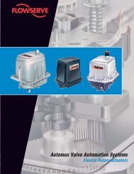
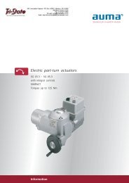
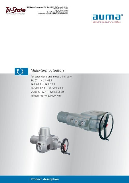
<strong>Multi</strong>-<strong>turn</strong> <strong>actuators</strong><br />
for open-close and modulating duty<br />
SA 07.1 – SA 48.1<br />
SAR 07.1 – SAR 30.1<br />
SAEx(C) 07.1 – SAEx(C) 40.1<br />
SAREx(C) 07.1 – SAREx(C) 30.1<br />
Torques up to 32,000 Nm<br />
Product description
Applications<br />
AUMA multi-<strong>turn</strong> <strong>actuators</strong> are used wherever the automation<br />
of a valve requires rotation, e.g. when using gate<br />
valves. The <strong>actuators</strong> can be adapted to suit the requirements<br />
of nearly all valve applications. This is achieved by:<br />
■<br />
■<br />
■<br />
an extremely wide torque range,<br />
various combination possibilities with AUMA valve gearboxes<br />
and controls,<br />
a large variety of versions.<br />
Energy<br />
: Power plants<br />
: Air pollution control<br />
: District heating<br />
: Pipelines<br />
Water/Wastewater<br />
: Water works<br />
: Sewage treatment plants<br />
: Pumping stations<br />
: Dams<br />
2 |<br />
Chemical industry<br />
: Chemical industry<br />
: Petrochemical industry<br />
: Pharmaceutical industry<br />
Others<br />
: Oil and gas industry<br />
: Air conditioning<br />
: Ship building industry<br />
: Steel mills<br />
: Cement plants<br />
: Food industry
Table of contents<br />
Applications/duty types 4<br />
Modular design – versions 6<br />
Design principle 8<br />
Summary of applications,<br />
functions, and equipment 9<br />
Service conditions 10<br />
Functions 12<br />
Signals/indication 18<br />
Integral controls 21<br />
Electrical connection<br />
for non-explosion-proof <strong>actuators</strong> 22<br />
Electrical connection<br />
for explosion-proof <strong>actuators</strong> 23<br />
Valve attachment 24<br />
Combinations with valve gearboxes 25<br />
<strong>Technical</strong> data 26<br />
Certificates 29<br />
Quality is not just a matter of trust 30<br />
The actuator specialist 31<br />
Literature 32<br />
Index 33<br />
AUMA worldwide 34<br />
Solutions for a world in motion<br />
This brochure will provide both the beginner and the<br />
expert with an overview of the functions and applications<br />
of AUMA SA/SAR multi-<strong>turn</strong> <strong>actuators</strong>. It is used as the<br />
basis to determine whether a device is suitable for the<br />
chosen application.<br />
For detailed product selection refer to the separate data<br />
sheets and price lists. On request, AUMA engineers within<br />
field service and within our subsidiaries can help you to<br />
find the correct device for the application.<br />
The latest detailed information on the SA and SAR<br />
multi-<strong>turn</strong> <strong>actuators</strong> can be found on the Internet under<br />
www.auma.com. All documents, including dimensional<br />
drawings, wiring diagrams and final inspection records (for<br />
supplied multi-<strong>turn</strong> <strong>actuators</strong>) are available on the Internet<br />
in a digitalised form.<br />
The SA/SAR multi-<strong>turn</strong> actuator version has been available<br />
since 1986. Ever since, the <strong>actuators</strong> have been continuously<br />
improved. They can be combined with the latest<br />
generation of AUMA actuator controls – enabled by the<br />
modular design principle of the AUMA product range.<br />
Both the mechanical interfaces as well as options for integration<br />
into a DCS are always up to date.<br />
Subject to change without notice.<br />
The product features and technical data provided do not express or imply any warranty.<br />
| 3
Applications/duty types<br />
AUMA automates valves; to put it in a nutshell, this is<br />
what AUMA <strong>actuators</strong> do. In other words: AUMA <strong>actuators</strong><br />
can be used for remote control of valves; either by an operation<br />
command manually triggered in the control room or<br />
within the framework of an automated process-controlled<br />
procedure. AUMA is an actuator specialist.<br />
According to the different valve designs, there are<br />
multi-<strong>turn</strong>, part-<strong>turn</strong> and linear <strong>actuators</strong>. This brochure puts<br />
the focus on multi-<strong>turn</strong> <strong>actuators</strong>. <strong>Multi</strong>-<strong>turn</strong> <strong>actuators</strong> are<br />
predominantly used for the automation of gate valves, for<br />
example, where more than one rotation of the valve shaft is<br />
required.<br />
Shutting off, positioning, controlling<br />
The second important selection criterion after the type of<br />
movement is the type of duty. Is the valve to be used as<br />
shut-off device (open-close duty), is the valve is to be positioned<br />
in mid-travel (positioning mode) or is the valve position<br />
to be changed at short intervals, i.e. to control the flow<br />
through a pipeline (modulating duty) These are essential factors<br />
for sizing the valve and the actuator as the load may<br />
vary considerably depending on the operation mode.<br />
OPEN-CLOSE duty and positioning duty<br />
OPEN-CLOSE duty<br />
The valve is operated relatively seldom, the time intervals<br />
can span between a few minutes up to several months.<br />
t 1<br />
t<br />
Typical operation in open-close duty<br />
[t 1 ] Running time. The maximum permissible running time without interruption<br />
is usually 15 min, optionally 30 min.<br />
Positioning duty<br />
The valve is operated to a specified intermediate position,<br />
e.g. to set a consistent flow rate. The same running time limits<br />
as in open-close duty apply.<br />
Consequently, there are AUMA <strong>actuators</strong> for open-close<br />
and positioning duty as well as <strong>actuators</strong> which meet the<br />
high requirements of modulating duty.<br />
Typical operation in positioning duty<br />
t<br />
AUMA multi-<strong>turn</strong> <strong>actuators</strong> mounted on gate valves in the kerosene tank<br />
farm at Chubu airport in Japan.<br />
AUMA explosion-proof <strong>actuators</strong> distribute the crude oil to different<br />
tanks in a tank farm in Northern Germany.<br />
4 |
Modulating duty<br />
The most distinctive feature of a closed-loop application is<br />
that changing conditions require frequent adjustment of the<br />
MOV. Sensitive closed-loop applications require adjustments<br />
within intervals of a few seconds.<br />
The demands on the actuator are high. Mechanical components<br />
and the motor must be designed correctly to withstand<br />
a large number of operations over a long time with no<br />
decline in the modulating accuracy.<br />
Types of duty for AUMA <strong>actuators</strong><br />
The correct AUMA actuator for the duty can be determined<br />
by the type designation.<br />
<strong>Multi</strong>-<strong>turn</strong> <strong>actuators</strong> for open-close and positioning<br />
duty<br />
AUMA multi-<strong>turn</strong> <strong>actuators</strong> for open-close and positioning<br />
duty are marked with the type designations SA, SAExC, and<br />
SAEx.<br />
Available sizes:<br />
Typical operation in modulating duty<br />
t<br />
■ SA 07.1 – SA 48.1<br />
■ SAExC 07.1 – SAExC 16.1<br />
■ SAEx 25.1 – SAEx 40.1<br />
As standard, the <strong>actuators</strong> conform to the types of duty<br />
S2 - 15 min or S2 - 30 min as an option.<br />
<strong>Multi</strong>-<strong>turn</strong> <strong>actuators</strong> for modulating duty<br />
AUMA multi-<strong>turn</strong> <strong>actuators</strong> for modulating duty are<br />
marked with the type designations SAR, SARExC, and SAREx.<br />
Available sizes:<br />
■ SAR 07.1 – SAR 30.1<br />
■ SARExC 07.1 – SARExC 16.1<br />
■ SAREx 25.1 – SAREx 30.1<br />
As standard, the <strong>actuators</strong> conform to the types of duty<br />
S4 - 25 % or S4 - 50 % as an option.<br />
Gate valves with mounted AUMA actuator for a dam project in Australia<br />
before installation.<br />
AUMA modulating actuator mounted on a control valve in a desalination<br />
plant.<br />
| 5
Modular design/versions<br />
Modular design – with or without controls<br />
Each application has its special requirements. For this reason,<br />
AUMA only builds <strong>actuators</strong> on demand – tailor-made to<br />
customer requirements. Due to the modular design of the<br />
AUMA product range, different features can be combined.<br />
For each actuator type, there is a large number of equipment<br />
variants.<br />
One of the fundamental benefits of AUMA’s modular<br />
design is the ability to add integral controls to the basic<br />
actuator.<br />
Actuators without integral controls<br />
If your plant design requires the control of the <strong>actuators</strong><br />
from a central point, e.g. from a PLC, AUMA supplies <strong>actuators</strong><br />
without controls, the so-called AUMA NORM version.<br />
NORM <strong>actuators</strong> supply unprocessed signals; the external<br />
controls have to process all signals to and from the <strong>actuators</strong><br />
according to the operation.<br />
NORM <strong>actuators</strong> have no switchgear for switching the<br />
actuator motor on or off. This switchgear, e.g. reversing<br />
contactors, has to be included within the external controls to<br />
ensure, for example, that the actuator motor is automatically<br />
switched off if the actuator signals that an end position has<br />
been reached.<br />
AUMA NORM <strong>actuators</strong> have no operating elements to<br />
operate the actuator electrically in the local mode. If this is<br />
required, separate local controls have to be installed and integrated<br />
into the control system.<br />
Actuators with integral controls<br />
After establishing the power supply, the <strong>actuators</strong> are<br />
ready for operation immediately. The actuator signals are processed<br />
locally. The required switching procedures are immediately<br />
performed within the integral controls, using the integral<br />
reversing contactors or thyristors.<br />
After connecting the power supply, the actuator can be<br />
operated immediately in the local mode, using the local controls.<br />
Extensive installation work for external controls is no longer<br />
required.<br />
The automatic phase correction ensures the correct direction<br />
of rotation even if the phases are crossed over during<br />
electrical installation.<br />
The high functionality of the controls relieves the DCS, so<br />
data exchange is reduced to a minimum.<br />
Integral controls are a prerequisite when connecting <strong>actuators</strong><br />
to a fieldbus.<br />
NORM <strong>actuators</strong> can also be retrofitted or supplemented<br />
at a later date.<br />
For further information on the integral controls refer to<br />
page 21 and the separate brochures:<br />
■<br />
■<br />
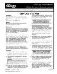
Product description<br />
Actuator controls AUMA MATIC<br />
Product description<br />
Actuator controls AUMATIC<br />
Due to the modular design principle, the multi-<strong>turn</strong> actuator may be supplied<br />
without controls or with AUMA MATIC or AUMATIC integral<br />
controls.<br />
6 |
[1] [2]<br />
[1] <strong>Multi</strong>-<strong>turn</strong> <strong>actuators</strong><br />
SA 07.1 – SA 16.1/SAR 07.1 – SAR 16.1<br />
without integral controls<br />
(AUMA NORM)<br />
■ Torques from 10 to 1,000 Nm<br />
[2] <strong>Multi</strong>-<strong>turn</strong> <strong>actuators</strong><br />
SA 25.1 – SA 48.1 /SAR 25.1 – SAR 30.1<br />
without integral controls<br />
(AUMA NORM)<br />
■ Torques from 630 to 32,000 Nm<br />
[3] [4]<br />
[5]<br />
[3] <strong>Multi</strong>-<strong>turn</strong> <strong>actuators</strong><br />
with AUMA MATIC integral controls<br />
The AUMA MATIC is ideal for simple OPEN -<br />
CLOSE applications (open-close duty) and for<br />
conventional control. If equipped accordingly, it<br />
may also be used for closed-loop control.<br />
Further information on page 21.<br />
[4] <strong>Multi</strong>-<strong>turn</strong> actuator<br />
with AUMATIC integral controls<br />
The AUMATIC is the all-rounder among<br />
AUMA controls. It is equipped with a micro<br />
controller and has a lot more functions than<br />
the AUMA MATIC. The AUMATIC is ideal for<br />
closed-loop control applications. And it is also<br />
the AUMATIC that is used for the implementation<br />
of the latest fieldbus system developments.<br />
Further information on page 21.<br />
[5] <strong>Multi</strong>-<strong>turn</strong> actuator<br />
with the controls on a wall bracket<br />
The controls can also be mounted separately<br />
from the actuator on a wall bracket. This<br />
is recommended if:<br />
■ limited space restricts the access to directly<br />
mounted controls<br />
■ high ambient temperatures in the surroundings<br />
of the actuator could affect the electronics,<br />
■ heavy valve vibration could influence the<br />
controls.<br />
| 7
Design principle<br />
[7a]<br />
[7b]<br />
[6]<br />
[6]<br />
[6]<br />
[1]<br />
[2]<br />
[5]<br />
[3]<br />
[4]<br />
[1] Motor<br />
Most <strong>actuators</strong> are equipped with robust<br />
3-phase asynchronous motors. 1-phase AC or<br />
DC motors are also available up to actuator size<br />
16.1.<br />
The motor is connected via an internal<br />
plug/socket connector (up to 16 A nominal current).<br />
This enables quick exchange of the motor,<br />
e.g. for change of output speed.<br />
Further information on page 12.<br />
[2] Control unit<br />
The control unit includes two measuring systems<br />
(limit switching and torque switching)<br />
which measure the travel or the torque present<br />
at the output drive. Further information on<br />
page 14.<br />
[3] Gearing<br />
The well proven principle of worm gearing,<br />
sometimes combined with a planetary gear, is<br />
used to reduce the motor speed to the required<br />
actuator output speed. The sliding worm is positioned<br />
between two stacks of springs on the<br />
worm shaft. The worm will be moved in relation<br />
to the torque. This axial displacement, as<br />
measure for the torque, is transmitted to the<br />
control unit via lever and gear wheels.<br />
[4] Valve attachment<br />
The mounting flange is according to<br />
EN ISO 5210 or DIN 3210.<br />
Various output drive types are available. Therefore<br />
it is possible to adapt to different types of<br />
valves. For further information refer to page 24.<br />
[5] Handwheel with change-over<br />
mechanism<br />
For commissioning or in an emergency the<br />
multi-<strong>turn</strong> actuator can be operated with the<br />
handwheel. By operating the red change-over<br />
lever the motor drive is disconnected and the<br />
manual drive engaged. Decoupling is possible<br />
with little force, even if the actuator is operated<br />
at full rated torque.<br />
When starting the motor the manual drive is<br />
automatically disengaged. During electric operation<br />
the handwheel does not rotate.<br />
[6] Electrical connection<br />
The electrical connection is made via a<br />
plug/socket connector, no matter whether the<br />
actuator is equipped with or without controls.<br />
For maintenance work, the actuator can be disconnected<br />
quickly from the power supply and<br />
control cables and can easily be reconnected.<br />
For multi-<strong>turn</strong> <strong>actuators</strong> from size 25.1, the<br />
motor cables are connected via terminals.<br />
Further information on page 22.<br />
[7] Integral controls (option)<br />
AUMA <strong>actuators</strong> with AUMA MATIC [7a] or<br />
AUMATIC [7b] integral controls are ready for<br />
operation as soon as the supply voltage has<br />
been connected. The actuator can easily be operated<br />
on site via the local controls.<br />
Via the installed switchgear, i.e. reversing<br />
contactors or thyristors, the integral controls<br />
automatically and immediately perform the required<br />
motor switching procedures.<br />
The electrical connection between integral controls<br />
and actuator is made by using a<br />
plug/socket connector.<br />
Further information on page 21.<br />
8 |
Summary of applications, functions, and equipment<br />
Standard ●<br />
Option ■<br />
SA<br />
07.1 – 48.1<br />
SAR<br />
07.1 – 30.1<br />
SAEx(C)<br />
07.1 – 40.1<br />
SAREx(C)<br />
07.1 – 30.1 Page<br />
Applications/duty type<br />
Open-close duty ● – ● – 4<br />
Positioning duty ● – ● – 4<br />
Modulating duty – ● – ● 5<br />
Service conditions<br />
Enclosure protection IP 67 ● ● ● ● 10<br />
Enclosure protection IP 68 ■ ■ ■ ■ 10<br />
High temperature version ■ – – – 10<br />
Low temperature version ■ ■ ■ ■ 10<br />
Corrosion protection KN ● ● ● ● 11<br />
Corrosion protection KS, KX ■ ■ ■ ■ 11<br />
Explosion protection – – ■ ■ 11<br />
Functions<br />
Motor operation ● ● ● ● 12<br />
Manual operation ● ● ● ● 8, 13<br />
Limit seating ● ● ● ● 13<br />
Torque seating ● ● ● ● 13<br />
Overload protection of the valve ● ● ● ● 15<br />
Protection against unauthorised operation ■ ■ ■ ■ 15<br />
Protection of the motor against overheating ● ● ● ● 16<br />
Protection against accidental changing of the valve position ● 1 ● 1 ● 1 ● 1 16<br />
Feedback signals 2 /indication<br />
Valve end positions ● ● ● ● 19<br />
Valve position ■ ■ ■ ■ 19, 20<br />
Intermediate positions ■ ■ ■ ■ 19<br />
Actuator/valve is running ■ ■ ■ ■ 19, 20<br />
Fault (excessive temperature) ● ● ● ● 19<br />
Fault (torque fault) ● ● ● ● 19<br />
Integral controls 3<br />
AUMA MATIC ■ ■ ■ ■ 21<br />
AUMATIC ■ ■ ■ ■ 21<br />
Electrical connection for non-explosion-proof devices<br />
Electrical connection with plug/socket ● ● – – 22<br />
Expanded connection compartments ■ ■ – – 22<br />
Double sealed ■ ■ – – 22<br />
Protection cover ■ ■ – – 22<br />
Parking frame ■ ■ – – 22<br />
Electrical connection for explosion-proof devices<br />
Plug/socket connector for explosion-proof <strong>actuators</strong> – – ● ● 23<br />
Plug-in terminal connection for explosion-proof <strong>actuators</strong> – – ■ ■ 23<br />
Double sealed – – ● ● 23<br />
Protection cover – – ■ ■ 23<br />
Parking frame – – ■ ■ 23<br />
Valve attachment according to EN ISO 5210/DIN 3210<br />
Output drive types B, B1 ● ● ● ● 24<br />
A, B2, B3, B3D, B4, C, D, DD, E ■ ■ ■ ■ 24<br />
Special output drives ■ ■ ■ ■ 24<br />
1<br />
For high output speeds, refer to separate technical data sheet<br />
2<br />
For <strong>actuators</strong> without integral controls, the actuator signals have to be processed accordingly in the higher level control system.<br />
3<br />
up to size 16.1<br />
| 9
Service conditions<br />
AUMA devices are used worldwide; in all climate zones, in<br />
industrial plants of all kinds under special local ambient conditions.<br />
AUMA devices have to operate reliably and for a long<br />
time under any conditions without requiring major maintenance<br />
work. For this very reason, AUMA has focussed on<br />
making AUMA devices resistant to the most unfavourable<br />
conditions and have adapted their protective measures to the<br />
state-of-the-art technology.<br />
Enclosure protection<br />
IP 67<br />
AUMA <strong>actuators</strong> conform to enclosure protection IP 67<br />
according to EN 60 529. IP 67 means protection against<br />
immersion up to max. 1 m head of water for max.<br />
30 minutes.<br />
IP 68<br />
AUMA <strong>actuators</strong> are available with improved enclosure<br />
protection IP 68 according to EN 60 529. IP 68 means protection<br />
against submersion up to 6 m head of water for max.<br />
72 hours. During submersion up to 10 operations are<br />
permissible.<br />
In order to guarantee the enclosure protection IP 68, suitable<br />
cable glands must be used. They are not part of the<br />
standard supply, but can be provided by AUMA on request.<br />
AUMA <strong>actuators</strong> at work – in Siberia and in the Sahara<br />
Ambient temperatures<br />
Types Actuator types Versions Temperature range<br />
SA<br />
<strong>Multi</strong>-<strong>turn</strong> <strong>actuators</strong><br />
for open-close duty<br />
SAR<br />
SAExC<br />
SAEx<br />
SARExC<br />
SAREx<br />
<strong>Multi</strong>-<strong>turn</strong> <strong>actuators</strong><br />
for modulating duty<br />
Explosion-proof multi-<strong>turn</strong> <strong>actuators</strong> for<br />
open-close duty<br />
Explosion-proof multi-<strong>turn</strong> <strong>actuators</strong> for<br />
open-close and modulating duty<br />
Standard<br />
Low temperature<br />
Extreme low temperature 1<br />
High temperature<br />
–25°C…+80°C<br />
–40°C…+60°C<br />
–60°C…+60°C<br />
0 °C ...+ 120 °C 2<br />
Standard<br />
–25°C…+60°C<br />
Low temperature<br />
–40°C…+60°C<br />
Extreme low temperature 1<br />
–60°C…+60°C<br />
Standard<br />
– 20 °C … + 40 °C/60 °C 3 /80 °C 4<br />
Low temperature<br />
– 40 °C … + 40 °C/60 °C 3<br />
Extreme low temperature 1<br />
– 50 °C … + 40 °C/60 °C 3<br />
High temperature<br />
–20°C…+80°C 4<br />
Standard<br />
Extreme low temperature 1 – 50 °C … + 40 °C/60 °C 3<br />
Low temperature<br />
– 40 °C … + 40 °C/60 °C 3<br />
If an actuator is equipped with directly mounted AUMA MATIC or AUMATIC integral controls, the maximum permissible<br />
ambient temperature is to + 70 °C, unless the actuator requires a lower temperature limit.<br />
1<br />
Device contains heating system for connection to external power supply 230 V AC or 115 V AC.<br />
2<br />
Valid for AUMA NORM version without electronic position transmitter RWG, with RWG max. + 80 °C<br />
3<br />
For the temperature range + 60 °C, special sizing is required for temperature class T4.<br />
4<br />
+ 80 °C possible in combination with explosion group IIB and temperature class T3<br />
10 |
Corrosion protection/colour<br />
Standard (KN)<br />
The standard AUMA corrosion protection KN is a high<br />
quality coating. This is suitable for outdoor installation and<br />
for slightly aggressive atmospheres with a low level of<br />
pollution.<br />
KS<br />
AUMA recommends this corrosion protection class for<br />
installation in occasionally or permanently aggressive atmospheres<br />
with a moderate pollutant concentration.<br />
KX<br />
AUMA recommends this corrosion protection class for<br />
installation in aggressive atmosphere with high humidity and<br />
a high pollutant concentration.<br />
Colour<br />
The standard colour of the finish coating is silver-grey (similar<br />
to RAL 3037). Other colours are available on request.<br />
Explosion protection<br />
For the installation of <strong>actuators</strong> in potentially hazardous or<br />
explosive areas, special protective measures are required.<br />
These are stipulated in the European Standards EN 50 014,<br />
50 018, and 50 019. The PTB (Physikalisch Technische<br />
Bundesanstalt, the German national test authority) and the<br />
BVS (German Mining Test Facility) as European test authorities<br />
have certified the conformity of the equipment with the<br />
mentioned standards.<br />
Explosion protection classification of the multi-<strong>turn</strong><br />
<strong>actuators</strong><br />
Types<br />
SAExC 07.1 – SAExC 16.1<br />
SARExC 07.1 – SARExC 16.1<br />
with and without integral controls<br />
SAExC 07.1 – SAExC 10.1<br />
SARExC 07.1 – SARExC 10.1<br />
without integral controls<br />
SAEx 25.1 – SAEx 40.1<br />
SAREx 25.1 – SAREx 30.1<br />
Classifications<br />
■ II2G EEx de IIC T4<br />
■ II2G c IIC T4<br />
■ II2D Ex tD A21 IP6X T130°C<br />
■ IM2ExdeI<br />
1<br />
■ II2G EEx ed IIB T4<br />
■ II2G c IIB T4<br />
■ II2D Ex tD A21 IP6X T130°C<br />
1<br />
With electronic position transmitter RWG 5020 Ex, the explosion protection<br />
classification corresponds to II2G EEx ed [ib] IIB T4<br />
(intrinsically safe)<br />
Certificates of Conformity from national test authorities in<br />
other countries, e.g. USA, Canada, CIS, Brazil, Japan, etc., are<br />
also available.<br />
| 11
Functions<br />
The function of an actuator is to electrically set a defined<br />
valve position, triggered by an operation command, e.g. from<br />
a process control system.<br />
This seemingly simple task has to be performed under the<br />
most diverse conditions, depending on the application. This<br />
includes different switch-off criteria and safety concepts. The<br />
connection to the control system also requires special actuator<br />
configuration to provide the optimum solution for this<br />
task.<br />
Furthermore, different protective equipment is required<br />
protecting both actuator and valve against damage or even<br />
destruction.<br />
The functions described in the following can be used to<br />
find a solution to more than 90 % of the possible tasks.<br />
In all AUMA subsidiaries, engineers will help you in finding<br />
the suitable actuator, especially for applications with special<br />
requirements.<br />
Motor operation<br />
During normal operation, the actuator is operated via the<br />
actuator controls which receive operation commands from<br />
the control room. If the actuator is also to be operated<br />
locally, additional local controls are required. If the actuator is<br />
equipped with optional integral AUMA controls, the local<br />
controls and the motor controls are always included.<br />
To meet the special valve automation requirements, AUMA<br />
uses specially designed electric motors which have both a<br />
compact design and a favourable torque curve. Starting from<br />
standstill, they provide a high torque to unseat sticky valves<br />
from their end position.<br />
T<br />
[1]<br />
[2]<br />
Torque T depending on the output speed n<br />
[1] AUMA 3-ph AC motor<br />
[2] Standard motor with identical power and larger size<br />
n<br />
Actuators are generally supplied with 3-phase AC motors.<br />
These asynchronous motors have a simple design and are<br />
robust during operation.<br />
The <strong>actuators</strong> can also be supplied with 1-phase AC or DC<br />
motors.<br />
12 |
Manual operation<br />
Electric <strong>actuators</strong> are always equipped with a handwheel.<br />
During commissioning, the actuator is operated manually by<br />
the handwheel for the purpose of setting the end<br />
positions.<br />
If the power supply fails, the valve can be operated via the<br />
handwheel. The manual drive is engaged via a change-over<br />
mechanism, the connection to the motor is disconnected at<br />
the same time. The handwheel does not rotate during motor<br />
operation.<br />
If the electric motor is switched on, the manual drive is<br />
automatically disconnected, and the transmission of torque<br />
between motor and gearing is restored.<br />
Switching off in the end positions<br />
Depending on the design of the valve and/or the application,<br />
the actuator is switched off in the end positions according<br />
to one of the following procedures stipulated by the valve<br />
manufacturer:<br />
■<br />
■<br />
Limit seating, i.e. at one of the set switching positions<br />
Torque seating. This type of seating is used if the valve has<br />
to be moved to end position CLOSED at a defined torque.<br />
AUMA <strong>actuators</strong> contain two independent measuring systems,<br />
limit switching and torque switching<br />
(see page 14).<br />
The type of seating has to be considered in the actuator<br />
controls.<br />
Limit seating<br />
n<br />
P<br />
Output speed n depending on the travel<br />
The actuator runs at nominal output speed up to tripping<br />
point P. When setting P, you have to account for the overrun<br />
of the actuator. The overrun is generated by the inertia of<br />
both the actuator and the valve and the delay time of the<br />
controls.<br />
Torque seating<br />
T<br />
[1]<br />
Torque T depending on the travel<br />
[1] Set tripping torque<br />
When reaching end position CLOSED the torque increases<br />
within the valve seat until the actuator is switched off after<br />
reaching the set value.<br />
| 13
Functions<br />
Control unit with limit and torque switching<br />
Controls can switch off the actuator via limit and torque<br />
seating in the end positions or in case of overload. The control<br />
unit (refer to illustration on page 8) includes two independent<br />
measuring systems which measure the travel or the<br />
torque present at the output drive.<br />
Control unit with micro switches<br />
Travel and incoming torque are recorded via a counter<br />
gear mechanism and a lever system within the control unit.<br />
When the set switching points are reached, the corresponding<br />
micro switches are operated via cams.<br />
Control unit with magnetic limit and torque<br />
transmitter (option)<br />
Position and the available torque are continuously<br />
recorded via Hall sensors. The valve position and the torque<br />
present within the valve are available as continuous signals.<br />
The magnetic limit and torque transmitter is designed to<br />
measure immediately the precise valve position once the<br />
power supply has been restored after a power failure. A reference<br />
operation is not required. The system does not require<br />
auxiliary energy, e.g. battery.<br />
■<br />
■<br />
The control unit contains:<br />
one torque switch each for the directions OPEN and<br />
CLOSE,<br />
one limit switch each for the end positions OPEN and<br />
CLOSED.<br />
If the control unit is used with an MWG, the actuator has<br />
to be equipped with the integral AUMATIC actuator controls.<br />
A significant advantage of this combination is that all actuator<br />
parameters can be set without opening the housing or<br />
the use of any tools.<br />
The switch signals trip the actuator according to the type<br />
of seating required.<br />
Limit and torque switches are available in several versions:<br />
■<br />
■<br />
■<br />
■<br />
Single switch<br />
one NC and one NO contact, not galvanically isolated.<br />
Tandem switch (option)<br />
for switching two different potentials.<br />
A tandem switch provides the electrical connection with<br />
the signal for switching off the actuator and another galvanically<br />
isolated signal.<br />
<strong>Tri</strong>ple switches (option)<br />
For applications where three different potentials are to be<br />
switched. The switch consists of one single and one tandem<br />
switch.<br />
Intermediate position switch (option)<br />
The so-called DUO limit switching contains an additional<br />
switch for setting intermediate switching points outside<br />
the end positions for each direction.<br />
In the basic version the switch contacts are made of silver.<br />
For voltages between 5 V and 50 V and extremely low currents,<br />
switches with gold plated contacts are recommended.<br />
14 |
Overload protection of the valve<br />
The torque switching acts as overload protection for the<br />
whole travel. Thereby the valve is protected against damage<br />
or destruction due to excessive torques.<br />
If excessive torque builds up at the valve’s closing element<br />
in an intermediate position, e.g. due to a trapped object, the<br />
torque switches will trip as soon as the set tripping torque<br />
is exceeded.<br />
Protection against unauthorised operation<br />
(option)<br />
The position of freely accessible valves may not be<br />
changed by unauthorised personnel.<br />
This can be prevented by securing the actuator handwheel<br />
by means of a locking device.<br />
Correct processing of the torque signal is the prerequisite<br />
for fully functional overload protection. This is automatically<br />
ensured for <strong>actuators</strong> with AUMA integral controls.<br />
T<br />
[1]<br />
Torque T depending on the travel<br />
| 15
Functions<br />
Protection of the motor against overheating<br />
The windings of the 3-phase AC and 1-phase AC motors<br />
contain thermoswitches or PTC thermistors which trip as<br />
soon as the temperature within the motor exceeds 140 °C.<br />
Should this be the case, the controls have to switch off the<br />
actuator.<br />
Protection against accidental changing of the<br />
valve position<br />
Gravity, vibration or forces acting upon the medium within<br />
a pipeline may lead to accidental changes in the valve position.<br />
This has to be prevented.<br />
Self-locking<br />
T<br />
140 °C<br />
115 °C<br />
[1]<br />
Due to their design, <strong>actuators</strong> counteract torques acting<br />
upon the output side with a load. If the load prevents the<br />
valve position from being changed from standstill, this is<br />
called self-locking.<br />
90 °C<br />
[2]<br />
t<br />
Most AUMA <strong>actuators</strong> are self-locking as standard. For<br />
<strong>actuators</strong> with high output speeds and certain actuator/gearbox<br />
combinations, self-locking can be achieved by mounting<br />
an anti-backdrive device.<br />
[1] <strong>Tri</strong>pping point<br />
[2] Switch-on point<br />
Thermoswitches or PTC thermistors offer far better protection<br />
than thermal overload relays, since the temperature rise<br />
is directly measured at the motor windings.<br />
Actuator type<br />
Thermoswitch<br />
PTC<br />
thermistor 2<br />
SA 07.1 – SA 48.1 Standard Option<br />
SAR 07.1 – SAR 30.1 Standard Option<br />
SAExC 07.1 – SAExC 16.1 Option 1 Standard<br />
SARExC 07.1 – SARExC 16.1 – Standard<br />
SAEx 25.1 – SAEx 40.1 Option 1 Standard<br />
SAREx 25.1 – SAREx 30.1 – Standard<br />
Self-braking<br />
If the valve is effectively brought to a standstill after operation,<br />
this is called self-braking. The braking torque of the<br />
actuator has to correspond to at least the maximum output<br />
torque.<br />
This requirement can also be met by using an<br />
anti-backdrive device or a brake motor.<br />
1<br />
According to EN 60079-14, a thermal overload relay (e.g. motor protection<br />
switch) must be installed for these <strong>actuators</strong> in addition to the<br />
thermoswitches.<br />
2<br />
For AUMA NORM <strong>actuators</strong>, a suitable PTC tripping device has to be<br />
included in the external controls. If the actuator is equipped with integral<br />
controls, the PTC tripping device is already included.<br />
16 |
Anti-backdrive device<br />
By using an LMS 07.1 – LMS 16.1 anti-backdrive device<br />
both self-locking and self-braking can be achieved. The<br />
retaining or braking torque corresponds to at least the maximum<br />
settable tripping torque of the actuator.<br />
With anti-backdrive devices, the use of expensive brake<br />
motors is no longer required for many applications. The<br />
anti-backdrive device is less expensive, much simpler and<br />
safer to use.<br />
[1]<br />
[2]<br />
[3] [4]<br />
[1] The anti-backdrive device is directly mounted to the output drive of<br />
the actuator.<br />
[2] The actuator with anti-backdrive device can either be directly<br />
mounted to the valve or a valve gearbox, in our example a GK multi-<strong>turn</strong><br />
gearbox [3] and a GS part-<strong>turn</strong> gearbox [4]. In this case, particularly high<br />
retaining or braking torques are available, since only the comparatively<br />
low torques at the gearbox input act upon the anti-backdrive device.<br />
The only exception are small-size gearboxes where the anti-backdrive device<br />
is installed at the gearbox output.<br />
| 17
Signals/indication<br />
Signals are the foundation for controlling a process flow.<br />
For this reason, <strong>actuators</strong> provide a number of signals which<br />
indicate the operational status of the actuator and of the<br />
valve.<br />
Many applications require that the actuator or the valve<br />
status can be provided locally. Depending on the equipment,<br />
the actuator offers various possibilities.<br />
Feedback signals<br />
The actuator signals are sent and evaluated by the actuator<br />
controls. For an AUMA NORM actuator, the signals are<br />
processed via external actuator controls, e.g. a PLC. For<br />
AUMA MATIC or AUMATIC <strong>actuators</strong>, the actuator signals are<br />
processed directly and locally; the higher level controls are<br />
provided with evaluated signals.<br />
Actuator signals<br />
[2]<br />
[1]<br />
TSC<br />
LSA<br />
Th<br />
LSC<br />
LSB<br />
TSO<br />
BL<br />
LSO<br />
RWG<br />
AUMA actuator fully equipped<br />
[1] Actuator controls, e.g. PLC<br />
[2] Feedback signals to the DCS<br />
[TSC] Torque switch signal in direction CLOSE<br />
[LSC] Limit switch signal in end position CLOSED<br />
[TSO] Torque switch signal in direction OPEN<br />
[LSO] Limit switch signal in end position OPEN<br />
[LSA] Intermediate position switch signal<br />
in direction CLOSE (option)<br />
[LSB] Intermediate position switch signal in direction OPEN (option)<br />
[BL] Blinker transmitter signal, option for <strong>actuators</strong><br />
for modulating duty<br />
[RWG] Electronic position transmitter 0/4 – 20 mA (option)<br />
[Th] Thermoswitch<br />
18 |
Feedback signals<br />
Feedback<br />
Valve end positions<br />
Valve position<br />
Intermediate positions, e.g. for<br />
starting up a pump when<br />
reaching a particular valve<br />
position<br />
Actuator/valve is operated<br />
Fault (excessive temperature)<br />
Fault (torque fault)<br />
Actuators without integral controls (AUMA NORM)<br />
When using tandem switches instead of the common single switches, the signals can be fed back twice<br />
as galvanically isolated signals.<br />
Limit and torque switch signals have to be evaluated within the external controls. When processing the signals it<br />
has to be considered whether the actuator is limit or torque seated in the end positions.<br />
For limit seating, the end position signal is generated by evaluating the limit switch signals.<br />
For torque seating, the end position feedback signal is generated by combining limit and torque switch signals.<br />
An optional position transmitter provides the external controls with the valve position either as a voltage signal<br />
or as a 0/4 – 20 mA current signal.<br />
As an option, the actuator contains two additional intermediate position switches, one for each direction<br />
(DUO limit switching)<br />
Can be provided by a blinker switch which is included in the basic version of open-close <strong>actuators</strong> and optionally<br />
available for modulating <strong>actuators</strong>.<br />
The higher level controls have to monitor the thermoswitches installed in the actuator motor. <strong>Tri</strong>pping of the<br />
thermoswitches has to switch off the actuator immediately to prevent it from being damaged. Consequently, the<br />
external controls have to generate a fault signal to be able to detect and eliminate a fault.<br />
<strong>Tri</strong>pping of a torque switch in mid-travel has to lead to immediate switching off of the actuator. Torque switch<br />
tripping in one of the end positions can also be part of normal operation. This is identified by the limit switch<br />
tripping at the same time. In all other cases, the tripping of the torque switch is to be interpreted as a fault. To<br />
be able to identify and eliminate a fault, the external controls have to provide a fault signal.<br />
Feedback signals for <strong>actuators</strong> with integral controls<br />
Integral controls have the following advantages:<br />
■<br />
■<br />
■<br />
For <strong>actuators</strong> with integral controls, the above mentioned<br />
feedback signals are directly made available. This reduces<br />
the number of signals to be led to the higher level<br />
controls.<br />
By means of enhanced diagnostic functions, the AUMATIC<br />
provides a number of other feedback signals which can be<br />
used if required.<br />
The controls have binary and analogue outputs or alternatively<br />
a fieldbus interface which can be used to transmit<br />
the signals to the DCS.<br />
Further information on these actuator types is available in<br />
the brochures:<br />
■<br />
■<br />
Product description<br />
Actuator controls AUMA MATIC<br />
Product description<br />
Actuator controls AUMATIC<br />
| 19
Signals/indication<br />
Local indication<br />
Actuators without integral controls<br />
(AUMA NORM)<br />
Actuators with integral controls<br />
Actuators with integral controls can also be equipped with<br />
the mechanical position indicator. Furthermore, the controls<br />
are complete with indication lights, or, in the case of the<br />
AUMATIC, a display, which indicate the operation status<br />
locally.<br />
For more detailed information on local indication, refer to<br />
the following brochures:<br />
On request, the actuator is equipped with a mechanical<br />
position indicator which can be used to view the valve position<br />
and also as running indication. The mechanical position<br />
indicator is clear and fully legible, even from a long distance.<br />
For AUMA NORM <strong>actuators</strong>, the actuator signals are exclusively<br />
processed by the external actuator controls. If signals<br />
generated within these controls are required as local indication,<br />
additional display elements and signal channels become<br />
necessary.<br />
■<br />
■<br />
Product description<br />
Actuator controls AUMA MATIC<br />
Product description<br />
Actuator controls AUMATIC<br />
20 |
Integral controls<br />
The integral controls evaluate the actuator signals and<br />
operation commands and perform the required switching<br />
procedures automatically and without delay, using the<br />
installed switchgear, reversing contactors or thyristors. The<br />
controls make the evaluated actuator signals available to the<br />
higher level controls as feedback signals.<br />
Actuators with integral controls are ready for operation<br />
immediately after establishing the power supply and can be<br />
operated via the operating elements.<br />
AUMA MATIC AM<br />
In its basic version, the AUMA MATIC is ideal for simple<br />
OPEN - CLOSE applications.<br />
AUMATIC AC<br />
As well as the AUMA MATIC’s basic functionality, the<br />
AUMATIC offers some other advantages, e.g.<br />
The AUMA MATIC provides end position indication, the<br />
selector switch position and a collective fault signal, all as<br />
feedback signals.<br />
The behaviour of the AUMA MATIC can be adapted to the<br />
application via programming switches, e.g. programming of<br />
the type of seating.<br />
Options:<br />
■<br />
■<br />
Three-position controller<br />
Fieldbus interface (Profibus DP or Modbus RTU)<br />
■<br />
■<br />
■<br />
■<br />
■<br />
■<br />
■<br />
Programmable signal relays<br />
Non-intrusive setting (option)<br />
Adaptive positioner (option)<br />
Fieldbus interfaces for Profibus DP, Modbus RTU,<br />
DeviceNet, Foundation Fieldbus (option)<br />
Monitoring and diagnostics<br />
Logging of operating data<br />
Cable-based or wireless programming interface for connecting<br />
a programming device<br />
AUMA MATIC local controls with push buttons, selector switches and indication<br />
lights<br />
Further literature<br />
Detailed information can be found in the brochure ‘Product<br />
description, Actuator controls AUMA MATIC’<br />
AUMATIC local controls with push buttons for operation and programming,<br />
selector switch, display with plain text display, indication lights and<br />
programming interface.<br />
Further literature<br />
Detailed information can be found in the brochure ‘Product<br />
description, Actuator controls AUMATIC<br />
| 21
Electrical connection for non-explosion-proof <strong>actuators</strong><br />
AUMA non-explosion-proof <strong>actuators</strong> use a “plug-in” type<br />
electrical connection. This applies to both power supply and<br />
1<br />
signal cables . The wiring made during installation remains<br />
undisturbed, even if the actuator has to be disconnected<br />
from the mains or the DCS, e.g. for maintenance purposes.<br />
The actuator can be quickly reconnected, wiring errors are<br />
avoided.<br />
The electrical connections can be used for <strong>actuators</strong> with<br />
or without controls.<br />
1<br />
For sizes SA 25.1 and larger the motor is connected to screw type<br />
terminals in the actuator terminal compartment. The controls are still<br />
wired to the AUMA plug/socket connector.<br />
The electrical connection is available in different sizes. The<br />
number of cable entries may vary. The cable entries usually<br />
have metric threads, Pg- or NPT-threads are also available.<br />
[1]<br />
[2] [3]<br />
[5]<br />
[4]<br />
[6]<br />
[7]<br />
All electric connections are based on the<br />
AUMA plug/socket connector with 50<br />
screw-type terminals for connecting the signal<br />
cables and three screw-type connections for<br />
connecting the supply voltage.<br />
[1] Standard S<br />
with three cable entries. The diameter is<br />
100 mm.<br />
[2] Enlarged terminal compartment SH (option)<br />
with up to six cable entries<br />
[3] Enlarged terminal compartment SE (option)<br />
with three cable entries. The diameter is<br />
135 mm. An intermediate frame is required for<br />
adapting to the actuator housing.<br />
[4] Double sealed intermediate frame<br />
(option)<br />
When removing the plug cover or due to<br />
leaky cable glands, ingress of dust and water<br />
into the housing is possible. This is prevented<br />
by inserting the double sealed intermediate<br />
frame between the electrical connection and<br />
actuator housing. The enclosure protection, IP<br />
67 or IP 68, will not be affected, even if the<br />
electrical connection is removed. The double<br />
sealed intermediate frame can be combined<br />
with any of the illustrated electrical<br />
connections.<br />
[5] Fieldbus connection SD<br />
If the actuator is equipped with actuator<br />
controls with a fieldbus interface, a special electrical<br />
connection is required. The connection of<br />
the power supply does not differ from the<br />
other electrical connections, a connection<br />
board for connecting the fieldbus cables is<br />
integrated into the plug.<br />
[6] Protection cover<br />
for protecting the plug compartment when<br />
plug is removed.<br />
[7] Parking frame<br />
for safe mounting of a disconnected plug.<br />
22 |
Electrical connection for explosion-proof <strong>actuators</strong><br />
1<br />
AUMA explosion-proof <strong>actuators</strong> use a “plug-in” type electrical<br />
connection. This applies to both power supply and signal<br />
cables. The wiring made during installation remains undisturbed,<br />
even if the actuator has to be disconnected from the<br />
mains or the DCS, e.g. for maintenance purposes. The actuator<br />
can be quickly reconnected and wiring errors are avoided.<br />
Explosion-proof connections are always double sealed: The<br />
flameproof enclosure inside the actuator remains intact even<br />
after removing the plug cover.<br />
The electrical connection is either designed in the protection<br />
type “Increased safety” or “Flameproof<br />
enclosure”.<br />
The electrical connections can be used for <strong>actuators</strong> with<br />
or without controls.<br />
1<br />
For the explosion-proof multi-<strong>turn</strong> <strong>actuators</strong> SAEx 25.1 û SAEx 40.1 the<br />
terminal connection cannot be plugged in.<br />
[s]<br />
[h]<br />
[1]<br />
[2a]<br />
[2b]<br />
[4]<br />
[5]<br />
[3]<br />
[1] Plug/socket connector with screw-type<br />
terminals KP<br />
with 38 screw-type connections for the signal<br />
cables. This connection type is the standard<br />
connection for explosion-proof <strong>actuators</strong>, even<br />
for those with a fieldbus interface. The connection<br />
can be supplied with a standard plug cover<br />
(s) with three cable entries or with a high (h)<br />
plug cover with up to six cable entries.<br />
The connection with the high (h) cover is also<br />
used for devices with integral controls and<br />
fieldbus interface.<br />
[2] Plug/socket connector with spring cage<br />
terminal blocks KES<br />
with up to 50 spring-cage terminal blocks<br />
for connecting signal cables. Used with operating<br />
voltages exceeding 525 V and/or if a large<br />
number of terminals are required. The electrical<br />
connection has up to 6 cable entries.<br />
The connection is available in protection type<br />
“Increased safety” [2a] or “Flameproof<br />
enclosure’”[2b].<br />
[3] Plug/socket connector with FO coupler<br />
KES<br />
This connection type is used for <strong>actuators</strong><br />
with AUMATIC integral controls with a fieldbus<br />
interface and signal transmission via fibre optics.<br />
The design basically corresponds to the<br />
plug/socket connector with spring cage terminals<br />
with the addition of an FO coupler.<br />
[4] Protection cover<br />
for protecting the plug compartment when<br />
the plug is removed.<br />
[5] Parking frame<br />
for safe mounting of a disconnected plug.<br />
The parking frame with mounted plug is protected<br />
against the ingress of both dust and water.<br />
| 23
Valve attachment<br />
The actuator is mounted to the valve using a mounting<br />
flange standardised according to EN ISO 5210 or DIN 3210.<br />
The output drive types are also manufactured according to<br />
these standards. They establish the mechanical connection<br />
between the output drive of the actuator and the valve stem<br />
or the valve shaft. The torque is transmitted from the actuator<br />
to the valve using this connection. There are various output<br />
drive types for available different valve types. The most<br />
common output drive types are illustrated below.<br />
[1] [2]<br />
[3]<br />
[4]<br />
[1] Output drive types B1, B2<br />
(EN ISO 5210), or B (DIN 3210)<br />
The output drive is integrated into the hollow<br />
shaft of the actuator. The torque is transmitted<br />
via a parallel key. Low radial loads can<br />
be accepted.<br />
[2] Output drive types B3 or B4 (EN ISO<br />
5210), or E (3210)<br />
The torque is transmitted via a parallel key.<br />
By using a plug sleeve, output drive type B1<br />
can easily be converted to output drive types<br />
B3 or B4.<br />
[3] Output drive type A<br />
(EN ISO 5210/DIN 3210)<br />
Stem nut for rising and non-rotating valve<br />
stems. The mounting flange together with the<br />
stem nut and thrust bearings form an assembly,<br />
which is suitable for accepting thrust. The unit<br />
is screwed to the actuator. Output drive type A<br />
cannot accept any radial loads.<br />
[4] Output drive type AF<br />
(EN ISO 5210/DIN 3210)<br />
Spring-loaded stem nut for rising and<br />
non-rotating valve stems. The springs compensate<br />
for dynamic thrust at high speeds or even<br />
for thermal expansion of the valve stem. This<br />
unit is screwed to the actuator which contains<br />
a hollow shaft with internal teeth.<br />
[5] Special output drive types<br />
(without illustration)<br />
Further output drive types are available besides<br />
those described:<br />
■ Pendulum stem nut AK<br />
■ Stem nut with plain bearings AG<br />
■ Hexagon in hollow shaft<br />
■ Insulated output drives IB1 and IB3<br />
For detailed information on special output<br />
drive types refer to the separate data sheets<br />
and price lists.<br />
24 |
Combinations with valve gearboxes<br />
The different valve gearboxes are an essential part of the<br />
modular AUMA product range. They can be combined with<br />
virtually any AUMA multi-<strong>turn</strong> actuator.<br />
Detailed information on gearboxes can be found in separate<br />
brochures and on separate technical data sheets.<br />
[1] [2] [3]<br />
[4] [5]<br />
[1] <strong>Multi</strong>-<strong>turn</strong> actuator with spur gearbox<br />
GST 10.1 – GST 40.1<br />
■ Torques up to 16,000 Nm<br />
The GST meets the following criteria:<br />
■ Expansion of the torque range of an actuator<br />
size. The combination of a small actuator<br />
with gearbox is often more cost-effective<br />
than a large actuator.<br />
■ Adaptations to special mounting conditions<br />
[2] <strong>Multi</strong>-<strong>turn</strong> actuator with bevel gearbox<br />
GK 10.2 – GK 40.2<br />
■ Torques up to 16,000 Nm<br />
The GK basically has the same functionality<br />
as the GST. Furthermore, so-called double-stem<br />
solutions can be provided by using two GK<br />
gearboxes and an SA actuator.<br />
[3] <strong>Multi</strong>-<strong>turn</strong> actuator with worm gearbox<br />
GS 50 – GS 500<br />
■ Torques up to 360,000 Nm<br />
The GS worm gearboxes convert the<br />
multi-<strong>turn</strong> movement at the output shaft of the<br />
multi-<strong>turn</strong> actuator into a part-<strong>turn</strong> movement,<br />
generally 90°. The combination of a multi-<strong>turn</strong><br />
actuator and worm gearbox forms a part-<strong>turn</strong><br />
actuator. Solutions are therefore available for<br />
large part-<strong>turn</strong> valves with high torque<br />
requirements.<br />
[4] <strong>Multi</strong>-<strong>turn</strong> actuator with lever gearbox<br />
GF 50.3 – GF 250.3<br />
■ Torques up to 32,000 Nm<br />
These combinations can be used to automate<br />
valves which are operated via a lever arrangement.<br />
[5] <strong>Multi</strong>-<strong>turn</strong> actuator with linear thrust<br />
unit LE 12.1 – LE 200.1<br />
■ Thrusts up to 217 kN<br />
■ Strokes up to 500 mm<br />
The linear thrust unit converts the rotary<br />
movement of the actuator output shaft into a<br />
linear movement. The combination of a<br />
multi-<strong>turn</strong> actuator and linear thrust unit forms<br />
a linear actuator.<br />
| 25
<strong>Technical</strong> data<br />
<strong>Multi</strong>-<strong>turn</strong> <strong>actuators</strong> for open-close duty<br />
The following data is valid for <strong>actuators</strong> with 3-phase AC motors with an S2 - 15 min duty type. For detailed information,<br />
restrictions for <strong>actuators</strong> with high output speeds as well as data on other motor types and types of duty refer to separate<br />
technical data sheets.<br />
Type<br />
Output speeds at 50<br />
Hz 1<br />
Setting range for tripping<br />
torque<br />
Valve mounting flange<br />
[rpm] [Nm] Standard (EN ISO 5210) Option (DIN 3210)<br />
SA/SAExC 07.1 4 – 180 10 – 30 F07 or F10 G0<br />
SA/SAExC 07.5 4 – 180 20 – 60 F07 or F10 G0<br />
SA/SAExC 10.1 4 – 180 40 – 120 F10 G0<br />
SA/SAExC 14.1 4 – 180 100 – 250 F14 G½<br />
SA/SAExC 14.5 4 – 180 200 – 500 F14 G½<br />
SA/SAExC 16.1 4 – 180 400 – 1,000 F16 G3<br />
SA/SAEx 25.1 4 – 90 630 – 2,000 F25 G4<br />
SA/SAEx 30.1 4 – 90 1,250 – 4,000 F30 G5<br />
SA/SAEx 35.1 4 – 45 2,500 – 8,000 F35 G6<br />
SA/SAEx 40.1 4 – 32 5,000 – 16,000 F40 G7<br />
SA 48.1 4 – 16 10,000 – 32,000 F48 –<br />
1<br />
Fixed output speeds, where each output speed is 1.4 times higher than the previous<br />
<strong>Multi</strong>-<strong>turn</strong> <strong>actuators</strong> for modulating duty<br />
The following data is valid for <strong>actuators</strong> with 3-phase AC motors with an S4 - 25 % duty type. For detailed information and<br />
data on other motor types and types of duty refer to separate technical data sheets.<br />
Type<br />
Output speeds<br />
at 50 Hz 1<br />
Setting range for<br />
tripping torques<br />
Permissible average torque for<br />
modulating duty<br />
Valve mounting flange<br />
Standard<br />
Option<br />
(EN ISO 5210) (DIN 3210)<br />
[rpm] [Nm] [Nm]<br />
SAR/SARExC 07.1 4 – 45 15 – 30 15 F07 or F10 G0<br />
SAR/SARExC 07.5 4 – 45 30 – 60 30 F07 or F10 G0<br />
SAR/SARExC 10.1 4 – 45 60 – 120 60 F10 G0<br />
SAR/SARExC 14.1 4 – 45 120 – 250 120 F14 G½<br />
SAR/SARExC 14.5 4 – 45 250 – 500 200 F14 G½<br />
SAR/SARExC 16.1 4 – 45 500 – 1,000 400 F16 G3<br />
SAR/SAREx 25.1 4 – 11 1,000 – 2,000 800 F25 G4<br />
SAR/SAREx 30.1 4 – 11 2,000 – 4,000 1,600 F30 G5<br />
1<br />
Fixed output speeds, where each output speed is 1.4 times higher than the previous<br />
26 |
Supply voltages/mains frequencies<br />
The standard supply voltages are listed below. Not all actuator versions or sizes are available with all motor types or voltages/frequencies.<br />
For detailed information refer to the separate electric data sheets.<br />
3-phase AC<br />
Voltages<br />
Frequency<br />
[V]<br />
[Hz]<br />
220; 230; 240; 380; 400; 415; 500 50<br />
440; 460; 480 60<br />
1-phase AC<br />
DC current<br />
Voltages<br />
[V]<br />
24; 48; 60; 110; 220<br />
Voltages<br />
Frequency<br />
[V]<br />
[Hz]<br />
230 50<br />
115 60<br />
Lifetime of multi-<strong>turn</strong> <strong>actuators</strong><br />
for open-close duty<br />
An operation cycle is based on an operation from CLOSED<br />
to OPEN and back to CLOSED, with a travel of 30 <strong>turn</strong>s per<br />
stroke.<br />
Type<br />
Operation cycles<br />
SA/SAExC 07.1 – 10.1 20,000<br />
SA/SAExC 14.1 – 16.1 15,000<br />
SA/SAEx 25.1 – 30.1 10,000<br />
SA/SAEx 35.1 – 48.1 5,000<br />
Lifetime of multi-<strong>turn</strong> <strong>actuators</strong><br />
for modulating duty<br />
The lifetime depends on the load and the number of<br />
starts. A high starting frequency will rarely improve the modulating<br />
accuracy. To reach the longest possible maintenance<br />
and fault-free operating time, the number of starts per hour<br />
chosen should be as low as possible for the process. This can<br />
be achieved by setting the modulating parameters<br />
accordingly.<br />
Type<br />
Modulating steps<br />
in millions<br />
min.<br />
Number of<br />
starts 1<br />
max/h<br />
SAR 07.1 – 10.1 5 1,200<br />
SARExC 07.1 – 10.1 5 900<br />
SAR 14.1 – 14.5 3.5 1,200 2<br />
SARExC 14.1 – 14.5 3.5 900 2<br />
SAR 16.1 3.5 900 2<br />
SARExC 16.1 3.5 600 2<br />
SAR 25.1 – 30.1 2.5 300<br />
SAREx 25.1 – 30.1 2.5 300<br />
1<br />
Based on the permissible average torque in the modulating duty according<br />
to ‘<strong>Technical</strong> data SAR’<br />
2<br />
Reduced number of starts for high output speeds<br />
| 27
<strong>Technical</strong> data<br />
Motor duty types (according to IEC 34-1)<br />
Depending on service conditions, open-close or modulating<br />
duty and running time, the motors are available with different<br />
duty types. The motors are not designed for permanent<br />
operation S1, but for short-time duty S2 or intermittent<br />
duty S4. Additional cooling of the motors is not required<br />
whilst a high enclosure protection is maintained.<br />
The time information for short-time duty S2 indicates the<br />
maximum permissible running time without interruption; the<br />
motor then has to cool down to ambient temperature. The<br />
percentages given for intermittent duty S4 indicate the percentage<br />
of the operation time in relation to the pause time.<br />
3-phase AC 1-phase AC DC current<br />
SA 07.1 – 48.1<br />
S2 - 15 min<br />
S2 - 30 min<br />
S2 - 10 min 1 S2 - 15 min<br />
SAR 07.1 – 30.1<br />
S4 - 25 %<br />
S4 - 50 %<br />
S4 - 25 % 2 –<br />
SAEx(C) 07.1 – 40.1<br />
S2 - 15 min S2 - 15 min 1<br />
S2 - 30 min S2 - 30 min 1 S2 - 15 min 3<br />
SAREx(C) 07.1 – 30.1 S4 - 25 % S4 - 25 % 2 –<br />
1<br />
up to size 14.5<br />
2<br />
up to size 14.1<br />
3<br />
for size 07.1<br />
Mounting position<br />
AUMA <strong>actuators</strong> (with or without integral controls), can be<br />
operated without restriction in any mounting position.<br />
Noise level<br />
The noise level caused by the multi-<strong>turn</strong> actuator does not<br />
exceed 72 dB (A).<br />
Vibration resistance<br />
according to EN 60068-2-6.<br />
The <strong>actuators</strong> are resistant to vibrations during start-up or<br />
failure of the plant up to 2 g, for a frequency range of 10 to<br />
200 Hz. However, a fatigue strength may not be derived<br />
from this.<br />
This data is valid for multi-<strong>turn</strong> <strong>actuators</strong> without integral<br />
controls with AUMA plug/socket connector or Ex-plug/socket<br />
connector (KP), but not in combination with gearboxes.<br />
28 |
Certificates<br />
EU directives<br />
Declaration of incorporation in accordance with<br />
Machinery Directive<br />
According to this EU directive, AUMA <strong>actuators</strong>, actuator<br />
controls and valve gearboxes are not complete machines. This<br />
means that a Declaration of conformity in accordance with<br />
the Machinery Directive cannot be issued by AUMA. AUMA’s<br />
Declaration of Incorporation confirms that during the design<br />
stage of the devices, the standards mentioned in the Machinery<br />
Directive were applied. The Declarations of Incorporation<br />
are included in the operation instructions of the devices.<br />
Only by mounting the devices to other components<br />
(valves, pipelines etc.) a ‘machine’ within the meaning of the<br />
directive is formed. Before commissioning this machine a Certificate<br />
of Conformity must be issued.<br />
Certificate of conformity in accordance with Low<br />
Voltage, EMC, and ATEX directive<br />
AUMA <strong>actuators</strong> fulfil the requirements of these EU directives,<br />
which has been proved in extensive tests. Therefore<br />
AUMA offers a Declaration of Conformity.<br />
The Declarations of Conformity are included in the operation<br />
instructions of the devices.<br />
Final inspection record<br />
After assembly, all <strong>actuators</strong> are thoroughly tested according<br />
to AUMA’s inspection specification and the torque<br />
switches are calibrated. The procedure is recorded on the<br />
final inspection record.<br />
Certificates<br />
To prove the suitability of the devices for special applications,<br />
notified bodies perform type tests on the devices. One<br />
example are the tests to which explosion-proof devices are<br />
subjected. If a device has passed the test, this is recorded in<br />
a certificate. For all explosion-proof devices mentioned in this<br />
brochure, the relevant certificates can be provided.<br />
Where can I get the certificates<br />
All certificates and records are provided by AUMA on<br />
request either as a hard or digital copy.<br />
The documents can be downloaded from the AUMA<br />
website around the clock; some of them are password protected.<br />
■<br />
www.auma.com<br />
Compulsory marking with CE mark<br />
AUMA products meet the requirements of the mentioned<br />
EU directives. The name plate is therefore marked with the<br />
CE mark.<br />
| 29
Quality is not just a matter of trust<br />
Actuators must be reliable and dependable. They determine<br />
the cycle of accurately defined work processes.<br />
But reliability does not begin in production. It begins with<br />
a well thought out design and careful selection of materials.<br />
This continues with conscientious production.<br />
At AUMA, quality management is monitored on a daily<br />
basis. Numerous customer and independent audits, backed<br />
by ISO 9001 and ISO 14001 certification confirm these high<br />
standards.<br />
30 |
The actuator specialist<br />
At AUMA, everything revolves around the electric actuator.<br />
In a world where industrial processes have become increasingly<br />
complex, concentration is an asset – while still being<br />
able to see the bigger picture.<br />
AUMA has to cope with a multitude of requirements from<br />
the most different applications and from every corner of the<br />
world - this is our daily business. We rise to this challenge by<br />
pursuing a clear but flexible product policy – supplying the<br />
ideal actuator to every customer.<br />
Since 1964, AUMA has established an excellent brand<br />
name in the world of <strong>actuators</strong>. Reliability and innovation are<br />
concepts which are closely linked with AUMA. This is above<br />
all to be credited to AUMA’s dedicated employees who work<br />
enthusiastically on the future of the actuator.<br />
For this purpose, you have to know your markets. Thinking<br />
globally means acting regionally. A comprehensive worldwide<br />
sales and service network ensures that there is a competent<br />
local contact for every customer.<br />
| 31
Literature<br />
Further literature<br />
Brochures<br />
■ Information<br />
Electric <strong>actuators</strong> and valve gearboxes according to ATEX<br />
directive 94/9/EC for the use in potentially explosive<br />
atmospheres<br />
Furthermore, there are electrical data sheets, dimension<br />
sheets, proposed wiring diagrams and wiring diagrams available.<br />
■<br />
■<br />
■<br />
Information<br />
Electric part-<strong>turn</strong> <strong>actuators</strong> SA/GS combinations<br />
Product description<br />
Actuator controls AUMA MATIC<br />
Product description<br />
Actuator controls AUMATIC<br />
<strong>Technical</strong> data<br />
■ <strong>Multi</strong>-<strong>turn</strong> <strong>actuators</strong> for open-close duty<br />
with 3-phase AC motors<br />
SA 07.1 – SA 48.1<br />
■<br />
■<br />
■<br />
■<br />
■<br />
■<br />
■<br />
■<br />
<strong>Multi</strong>-<strong>turn</strong> <strong>actuators</strong> for open-close duty<br />
with 1-phase AC motors<br />
SA 07.1 – SA 14.5<br />
<strong>Multi</strong>-<strong>turn</strong> <strong>actuators</strong> for open-close duty<br />
with DC motors<br />
SA 07.1 – SA 16.1<br />
<strong>Multi</strong>-<strong>turn</strong> <strong>actuators</strong> for open-close duty<br />
with 3-phase AC motors<br />
SAExC 07.1 – SAExC 16.1<br />
<strong>Multi</strong>-<strong>turn</strong> <strong>actuators</strong> for open-close duty<br />
with 3-phase AC motors<br />
SAEx 25.1 – SAEx 40.1<br />
<strong>Multi</strong>-<strong>turn</strong> <strong>actuators</strong> for modulating duty<br />
with 3-phase AC motors<br />
SAR 07.1 – SAR 30.1<br />
<strong>Multi</strong>-<strong>turn</strong> <strong>actuators</strong> for modulating duty<br />
with 1-phase AC motors<br />
SAR 07.1 – SAR 14.1<br />
<strong>Multi</strong>-<strong>turn</strong> <strong>actuators</strong> for modulating duty<br />
with 3-phase AC motors<br />
SARExC 07.1 – SARExC 16.1<br />
<strong>Multi</strong>-<strong>turn</strong> <strong>actuators</strong> for modulating duty<br />
with 3-phase AC motors<br />
SAREx 25.1 – SAREx 30.1<br />
The latest issues of all documentation can be downloaded<br />
as PDF files from www.auma.com.<br />
32 |
Index<br />
A<br />
Ambient temperatures 10<br />
AUMA MATIC 7,21<br />
AUMA plug/socket connector 8<br />
AUMATIC 7,21<br />
B<br />
Bevel gearbox 25<br />
C<br />
CE mark 29<br />
Colour 11<br />
Controls 7<br />
Corrosion protection 11<br />
E<br />
Electrical connection 8<br />
EMC directive 29<br />
Enclosure protection IP 10<br />
EU directives 29<br />
Explosion protection 11<br />
F<br />
Functional test 29<br />
I<br />
Integral controls 7<br />
L<br />
Lifetime 27<br />
Limit seating 13<br />
Limit switches 14<br />
Limit switching 13<br />
Linear thrust unit 25<br />
Literature 32<br />
M<br />
Manual operation 8<br />
Modulating duty 5<br />
Motor protection 16<br />
Motors 8,16<br />
Mounting position 28<br />
N<br />
Noise level 28<br />
O<br />
Open-close duty 5<br />
Overload protection 15<br />
P<br />
Painting 11<br />
Parking frame 22 - 23<br />
Plug sleeve 24<br />
Plug/socket connector 8,23<br />
Protection cover 22 - 23<br />
PTC thermistors 16<br />
S<br />
Spur gearbox 25<br />
T<br />
Thermoswitches 16<br />
Torque seating 13<br />
Torque switches 14<br />
Torque switching 13,15<br />
Type of seating 13<br />
V<br />
Valve attachment 8<br />
Vibration resistance 28<br />
W<br />
Wall bracket 7<br />
Worm gearbox 25<br />
| 33
AUMA worldwide<br />
Europe<br />
AUMA Riester GmbH & Co. KG<br />
Plant Müllheim<br />
DE-79373 Müllheim<br />
Tel +49 7631 809 - 0<br />
riester@auma.com<br />
www.auma.com<br />
Plant Ostfildern-Nellingen<br />
DE-73747 Ostfildern<br />
Tel +49 711 34803 - 0<br />
riester@wof.auma.com<br />
Service Center Cologne<br />
DE-50858 Köln<br />
Tel +49 2234 2037 - 9000<br />
Service@sck.auma.com<br />
Service Center Magdeburg<br />
DE-39167 Niederndodeleben<br />
Tel +49 39204 759 - 0<br />
Service@scm.auma.com<br />
Service Center Bavaria<br />
DE-85386 Eching<br />
Tel +49 81 65 9017- 0<br />
Riester@scb.auma.com<br />
AUMA Armaturenantriebe GmbH<br />
AT-2512 <strong>Tri</strong>buswinkel<br />
Tel +43 2252 82540<br />
office@auma.at<br />
www.auma.at<br />
AUMA (Schweiz) AG<br />
CH-8965 Berikon<br />
Tel +41 566 400945<br />
RettichP.ch@auma.com<br />
AUMA Servopohony spol. s.r.o.<br />
CZ-10200 Praha 10<br />
Tel +420 272 700056 / 704125<br />
auma-s@auma.cz<br />
www.auma.cz<br />
OY AUMATOR AB<br />
FI-02230 Espoo<br />
Tel +358 9 5840 22<br />
auma@aumator.fi<br />
www.aumator.fi<br />
AUMA France S.A.R.L.<br />
FR-95157 Taverny Cedex<br />
Tel +33 1 39327272<br />
info@auma.fr<br />
www.auma.fr<br />
AUMA ACTUATORS Ltd.<br />
GB- Clevedon North Somerset BS21 6QH<br />
Tel +44 1275 871141<br />
mail@auma.co.uk<br />
www.auma.co.uk<br />
AUMA ITALIANA S.r.l. a socio unico<br />
IT-20023 Cerro Maggiore (MI)<br />
Tel +39 0331 51351<br />
info@auma.it<br />
www.auma.it<br />
AUMA BENELUX B.V.<br />
NL-2314 XT Leiden<br />
Tel +31 71 581 40 40<br />
office@benelux.auma.com<br />
www.auma.nl<br />
AUMA Polska Sp. z o.o.<br />
PL-41-310 Dabrowa Górnicza<br />
Tel +48 32 261 56 68<br />
R.Ludzien@auma.com.pl<br />
www.auma.com.pl<br />
OOO Priwody AUMA<br />
RU-141400 Moscow region<br />
for mail: 124365 Moscow a/ya 11<br />
Tel +7 495 221 64 28<br />
aumarussia@auma.ru<br />
www.auma.ru<br />
ERICHS ARMATUR AB<br />
SE-20039 Malmö<br />
Tel +46 40 311550<br />
info@erichsarmatur.se<br />
www.erichsarmatur.se<br />
GRØNBECH & SØNNER A/S<br />
DK-2450 København SV<br />
Tel +45 33 26 63 00<br />
GS@g-s.dk<br />
www.g-s.dk<br />
IBEROPLAN S.A.<br />
ES-28027 Madrid<br />
Tel +34 91 3717130<br />
iberoplan@iberoplan.com<br />
D. G. Bellos & Co. O.E.<br />
GR-13671 Acharnai Athens<br />
Tel +30 210 2409485<br />
info@dgbellos.gr<br />
SIGURD SØRUM A. S.<br />
NO-1300 Sandvika<br />
Tel +47 67572600<br />
post@sigurd-sorum.no<br />
INDUSTRA<br />
PT-2710-297 Sintra<br />
Tel +351 2 1910 95 00<br />
jpalhares@tyco-valves.com<br />
MEGA Endüstri Kontrol Sistemieri Tic. Ltd. Sti.<br />
TR-06810 Ankara<br />
Tel +90 312 217 32 88<br />
megaendustri@megaendustri.com.tr<br />
CTS Control Limited Liability Company<br />
UA-02099 Kiyiv<br />
Tel +38 044 566-9971, -8427<br />
v_polyakov@cts.com.ua<br />
Africa<br />
AUMA South Africa (Pty) Ltd.<br />
ZA-1560 Springs<br />
Tel +27 11 3632880<br />
aumasa@mweb.co.za<br />
A.T.E.C.<br />
EG- Cairo<br />
Tel +20 2 23599680 - 23590861<br />
atec@intouch.com<br />
34 |
America<br />
AUMA ACTUATORS INC.<br />
US-PA 15317 Canonsburg<br />
Tel +1 724-743-AUMA (2862)<br />
mailbox@auma-usa.com<br />
www.auma-usa.com<br />
AUMA Chile Respresentative Office<br />
CL-9500414 Buin<br />
Tel +56 2 821 4108<br />
aumachile@adsl.tie.cl<br />
LOOP S. A.<br />
AR-C1140ABP Buenos Aires<br />
Tel +54 11 4307 2141<br />
contacto@loopsa.com.ar<br />
Asvotec Termoindustrial Ltda.<br />
BR-13190-000 Monte Mor/ SP.<br />
Tel +55 19 3879 8735<br />
atuador.auma@asvotec.com.br<br />
TROY-ONTOR Inc.<br />
CA-L4N 5E9 Barrie Ontario<br />
Tel +1 705 721-8246<br />
troy-ontor@troy-ontor.ca<br />
MAN Ferrostaal de Colombia Ltda.<br />
CO- Bogotá D.C.<br />
Tel +57 1 401 1300<br />
dorian.hernandez@manferrostaal.com<br />
www.manferrostaal.com<br />
PROCONTIC Procesos y Control Automático<br />
EC- Quito<br />
Tel +593 2 292 0431<br />
info@procontic.com.ec<br />
IESS de Mexico, S.A. de C.V.<br />
MX-C.P. 02900 Mexico D.F.<br />
Tel +52 55 55 56 1701<br />
informes@iess.com.mx<br />
Corsusa International S.A.C.<br />
PE- Miralflores - Lima<br />
Tel +511444-1200 / 0044 / 2321<br />
corsusa@corsusa.com<br />
www.corsusa.com<br />
PASSCO Inc.<br />
PR-00936-4153 San Juan<br />
Tel +18 09 78 77 20 87 85<br />
Passco@prtc.net<br />
Suplibarca<br />
VE- Maracaibo Estado, Zulia<br />
Tel +58 261 7 555 667<br />
suplibarca@intercable.net.ve<br />
Asia<br />
AUMA Actuators (Tianjin) Co., Ltd.<br />
CN-300457 Tianjin<br />
Tel +86 22 6625 1310<br />
mailbox@auma-china.com<br />
www.auma-china.com<br />
AUMA (INDIA) PRIVATE LIMITED<br />
IN-560 058 Bangalore<br />
Tel +91 80 2839 4655<br />
info@auma.co.in<br />
www.auma.co.in<br />
AUMA JAPAN Co., Ltd.<br />
JP-210-0848 Kawasaki-ku,<br />
Kawasaki-shi Kanagawa<br />
Tel +81 44 329 1061<br />
mailbox@auma.co.jp<br />
www.auma.co.jp<br />
AUMA ACTUATORS (Singapore) Pte Ltd.<br />
SG-569551 Singapore<br />
Tel +65 6 4818750<br />
sales@auma.com.sg<br />
www.auma.com.sg<br />
Al Ayman Industrial. Eqpts<br />
AE- Dubai<br />
Tel +971 4 3682720<br />
auma@emirates.net.ae<br />
PERFECT CONTROLS Ltd.<br />
HK- Tsuen Wan, Kowloon<br />
Tel +852 2493 7726<br />
joeip@perfectcontrols.com.hk<br />
DW Controls Co., Ltd.<br />
KR-153-803 Seoul Korea<br />
Tel +82 2 2113 1100<br />
sichoi@actuatorbank.com<br />
www.actuatorbank.com<br />
Al-Arfaj Engineering Co WLL<br />
KW-22004 Salmiyah<br />
Tel +965 481-7448<br />
info@arfajengg.com<br />
www.arfajengg.com<br />
Petrogulf W.L.L<br />
QA- Doha<br />
Tel +974 4350 151<br />
pgulf@qatar.net.qa<br />
Sunny Valves and Intertrade <strong>Corp</strong>. Ltd.<br />
TH-10120 Yannawa Bangkok<br />
Tel +66 2 2400656<br />
sunnyvalves@inet.co.th<br />
www.sunnyvalves.co.th/<br />
Top Advance Enterprises Ltd.<br />
TW- Jhonghe City Taipei Hsien (235)<br />
Tel +886 2 2225 1718<br />
support@auma-taiwan.com.tw<br />
www.auma-taiwan.com.tw<br />
Australia<br />
BARRON GJM Pty. Ltd.<br />
AU-NSW 1570 Artarmon<br />
Tel +61 294361088<br />
info@barron.com.au<br />
www.barron.com.au<br />
2008-05-13<br />
| 35
[1] <strong>Multi</strong>-<strong>turn</strong> <strong>actuators</strong><br />
SA 07.1 – SA 48.1<br />
Torques from 10 to 32,000 Nm<br />
Output speeds from 4 to 180 rpm<br />
[2] <strong>Multi</strong>-<strong>turn</strong> <strong>actuators</strong> SA/SAR<br />
with controls AUMATIC<br />
Torques from 10 to 1,000 Nm<br />
Output speeds from 4 to 180 rpm<br />
[3] Linear <strong>actuators</strong> SA/LE<br />
Combination of multi-<strong>turn</strong> actuator SA<br />
with linear thrust unit LE<br />
Thrusts from<br />
4 kN to 217 kN<br />
Strokes up to 500 mm<br />
Linear speeds<br />
from 20 to 360 mm/min<br />
[4] Part-<strong>turn</strong> <strong>actuators</strong><br />
SG 05.1 – SG 12.1<br />
Torques from 100 to 1,200 Nm<br />
Operating times for 90° from 4 to 180 s<br />
[5] Part-<strong>turn</strong> <strong>actuators</strong> SA/GS<br />
Combination of multi-<strong>turn</strong> actuator SA with<br />
part-<strong>turn</strong> gearbox GS<br />
Torques up to 675,000 Nm<br />
[6] Bevel gearboxes<br />
GK 10.2 – GK 40.2<br />
Torques up to 16,000 Nm<br />
[7] Spur gearboxes<br />
GST 10.1 – GST 40.1<br />
Torques up to 16,000 Nm<br />
[8] Worm gearboxes with base and lever<br />
GF 50.3 – GF 250.3<br />
Torques up to 32,000 Nm<br />
AUMA Riester GmbH & Co. KG<br />
P.O.Box 1362<br />
D-79379 Muellheim<br />
Tel +49 7631-809-0<br />
Fax +49 7631-809-1250<br />
riester@auma.com<br />
[1] [2] [3]<br />
[4] [5]<br />
[6] [7] [8]<br />
Certificate Registration No.<br />
12 100/104 4269<br />
Subject to change without notice.<br />
The product features and technical data provided do not express or imply any warranty.<br />
Y000.038/002/en/1.06<br />
For detailed information about AUMA products refer to the Internet: www.auma.com