R Series IOM
R Series IOM
R Series IOM
- No tags were found...

Create successful ePaper yourself
Turn your PDF publications into a flip-book with our unique Google optimized e-Paper software.
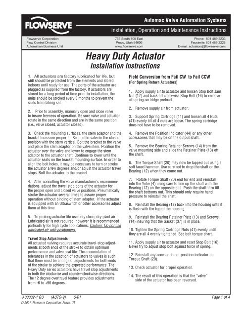
Automax Valve Automation SystemsInstallation, Operation and Maintenance InstructionsFlowserve Corporation 765 South 100 East Phone: 801 489 2233Flow Control Division Provo, Utah 84606 Facsimile: 801 489 2228Automation Business Unit www.flowserve.com E-mail: actuators@flowserve.com1. All actuators are factory lubricated for life, butstill should be protected from the elements and storedindoors until ready for use. The ports of the actuator areplugged as supplied from the factory. If actuators arestored for a long period of time prior to installation, theunits should be stroked every 3 months to prevent theseals from taking set.2. Prior to assembly, manually open and close valveto insure freeness of operation. Be sure valve and actuatorrotate in the same direction and are in the same position(i.e., valve closed, actuator closed).Heavy Duty ActuatorInstallation InstructionsField Conversion from Fail CW to Fail CCW(For Spring Return Actuators)1. Apply supply air to actuator and loosen Stop Bolt JamNut (17) and back off clockwise Stop Bolt (16) to removeall spring cartridge preload.2. Remove supply air from actuator.3. Support Spring Cartridge (11) and loosen all 4 Nuts(41) evenly till all 4 nuts are loose. The spring cartridgedoes not have to be removed.3. Check the mounting surfaces, the stem adaptor and thebracket to assure proper fit. Secure the valve in the closedposition with the stem vertical. Bolt the bracket to the valveand place the stem adaptor on the valve stem. Position theactuator over the valve and lower to engage the stemadaptor to the actuator shaft. Continue to lower until theactuator seats on the bracket mounting surface. In order toalign the bolt holes, it may be necessary to turn or strokethe actuator a few degrees and/or adjust the actuator travelstops. Bolt the actuator to the bracket.4. After consulting the valve manufacturer's recommendations,adjust the travel stop bolts of the actuator forthe proper open and closed valve positions. Pneumaticallystroke the actuator several times to assure properoperation without binding of stem adaptor. If the actuatoris equipped with an Ultraswitch or other accessories adjustthem at this time.5. To prolong actuator life use only clean, dry plant air.Lubricated air is not required, however it is recommendedparticularly for high cycle applications. Caution: Do not uselubricated air with positioners.Travel Stop AdjustmentsAll actuated valving requires accurate travel-stop adjustmentsat both ends of the stroke to obtain optimumperformance and valve seat life. The accumulation oftolerances in the adaption of actuators to valves is suchthat there must be a range of adjustments for both endsof the stroke to achieve the expected performance. TheHeavy Duty series actuators have travel stop adjustmentsin both the clockwise and counter-clockwise directions.The 12 degree overtravel feature provides adjustmentsfrom -6 to +96 degrees.4. Remove the Position Indicator (44) or any otheraccessories that may be on the output shaft.5. Remove the Bearing Retainer Screws (14) from thevalve mounting side and slide the Retainer Plate (13) offthe shaft.6. The Torque Shaft (20) may now be tapped out using asoft faced hammer. Use care not to drop the shaft or theBearing (12) when they come out.7. Rotate Torque Shaft (20) end for end and reinstallinto the Yoke (4) using care to line up the shaft with theBearing (12) on the opposite end. Push the shaft thru tillthe shaft bottoms out. This should only require handpressure to reinstall the shaft.8. Reinstall the Bearing (12) back into the housing until itis flush with the top of the housing.9. Reinstall the Bearing Retainer Plate (13) and Screws(14) insuring that the Gasket (37) is in place.10. Tighten the Spring Cartridge Nuts (41) evenly untilthey are all 4 evenly tightened. See bolt torque chart.11. Apply supply air to actuator and reset Stop Bolt (16).Never try to adjust stop bolt against force of spring.12. Reinstall any accessories or position indicator onTorque Shaft (20).13. Check actuator for proper operation.14. The result of this operation is that the “valve”side of the actuator has been reversed.A00032-1 GU (AUTO-9) 5/01 Page 1 of 4© 2001, Flowserve Corporation, Provo, UT
Automax Valve Automation SystemsInstallation, Operation and Maintenance InstructionsFlowserve Corporation 765 South 100 East Phone: 801 489 2233Flow Control Division Provo, Utah 84606 Facsimile: 801 489 2228Automation Business Unit www.flowserve.com E-mail: actuators@flowserve.comParts & MaterialsItem Description Material Qty.1 Housing Ductile Iron 12 Piston Rod Bearing Bronze 23 Piston Rod Steel/Chrome 14 Yoke Ductile Iron 15 Yoke Pin Steel 16 Yoke Pin Roller Steel 27 Yoke Pin Retaining Ring Steel 28 Inspection Cover Steel 19 Inspection Cover Screw Steel 610 Inspection Cover Lockwasher Steel 611 Spring Cartridge/Rod Cover Steel 112 Torque Shift Bearing Steel 213 Bearing Retainer Plate Steel 214 Bearing Retainer Screw Steel 815 Bearing Retainer Lockwasher Steel 816 Stop Bolt Steel 217 Stop Bolt Jam Nut Steel 218 Stop Bolt Washer Steel 219 Yoke Key Steel 120 Torque Shaft Steel 121* Piston Rod Seal Nitrile 122 Adaptor Steel 123 Cylinder Steel/Chrome 1* Recommended Spare PartsItem Description Material Qty.24 Piston Steel 125 Piston Bolt Steel 126 Piston Bolt Lockwasher Steel 127 Tie Rod Steel 428 Tie Rod Locknut Steel/Nylon 429 Endcap Steel 130* Pressure Cylinder Seal Nitrile 231* Piston Cylinder Seal Nitrile 132* Piston Face Seal Nitrile 133* Adaptor Bolt Thread Seal Nitrile/Steel 434* Adaptor Gasket - Press. Slide Fiber 135* Inspection Cover Gasket Fiber 136 Breather Plug Bronze 137* Bearing Retainer Gasket Fiber 238* Torque Shaft Seal Nitrile 239* S.C./Rod Cover Gasket Fiber 140 Bolt (Rod Cover) - DA Only Steel 441 S.C./Rod Cover Nut Steel 442 S.C./Rod Cover Lockwasher Steel 443 Adaptor Bolt - Pressure Slide Steel 444 Position Indicator Steel 145 Position Indicator Bolt Steel 246 Position Indicator Lockwasher Steel 2A00032-1 GU (AUTO-9) 5/01 Page 4 of 4© 2001, Flowserve Corporation, Provo, UT