

ISOLATED 5-V FULL & HALF-DUPLEX RS-485 TRANSCEIVERS ...
ISOLATED 5-V FULL & HALF-DUPLEX RS-485 TRANSCEIVERS ...
ISOLATED 5-V FULL & HALF-DUPLEX RS-485 TRANSCEIVERS ...

You also want an ePaper? Increase the reach of your titles
YUMPU automatically turns print PDFs into web optimized ePapers that Google loves.
1<br />
1FEATURES<br />
APPLICATIONS<br />
• 4000-V PEAK Isolation<br />
• Security Systems<br />
• Bus-Pin ESD Protection<br />
• Chemical Production<br />
– 16 kV HBM Between Bus Pins and GND2 • Factory Automation<br />
– 6 kV HBM Between Bus Pins and GND1 • Motor/Motion Control<br />
• 1/8 Unit Load – Up to 256 Nodes on a Bus<br />
• HVAC and Building Automation Networks<br />
• Networked Security Stations<br />
• Meets or Exceeds TIA/EIA <strong>RS</strong>-<strong>485</strong><br />
Requirements ISO3080 Full-Duplex 200 kbps<br />
• Signaling Rates up to 20 Mbps ISO3086 Full-Duplex 20 Mbps<br />
• Thermal Shutdown Protection ISO3082 Half-Duplex 200 kbps<br />
• Low Bus Capacitance – 16 pF (Typ) ISO3088 Half-Duplex 20 Mbps<br />
• 50 kV/µs Typical Transient Immunity<br />
• Fail-safe Receiver for Bus Open, Short, Idle<br />
• 3.3-V Inputs are 5-V Tolerant<br />
DESCRIPTION<br />
ISO3080, ISO3086<br />
ISO3082, ISO3088<br />
www.ti.com ............................................................................................................................................................... SLOS581A–MAY 2008–REVISED JUNE 2008<br />
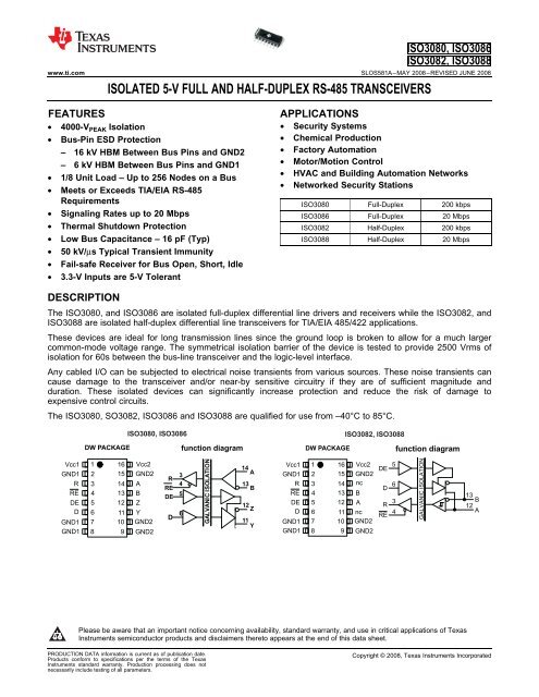
<strong>ISOLATED</strong> 5-V <strong>FULL</strong> AND <strong>HALF</strong>-<strong>DUPLEX</strong> <strong>RS</strong>-<strong>485</strong> TRANSCEIVE<strong>RS</strong><br />
The ISO3080, and ISO3086 are isolated full-duplex differential line drivers and receivers while the ISO3082, and<br />
ISO3088 are isolated half-duplex differential line transceivers for TIA/EIA <strong>485</strong>/422 applications.<br />
These devices are ideal for long transmission lines since the ground loop is broken to allow for a much larger<br />
common-mode voltage range. The symmetrical isolation barrier of the device is tested to provide 2500 Vrms of<br />
isolation for 60s between the bus-line transceiver and the logic-level interface.<br />
Any cabled I/O can be subjected to electrical noise transients from various sources. These noise transients can<br />
cause damage to the transceiver and/or near-by sensitive circuitry if they are of sufficient magnitude and<br />
duration. These isolated devices can significantly increase protection and reduce the risk of damage to<br />
expensive control circuits.<br />
The ISO3080, SO3082, ISO3086 and ISO3088 are qualified for use from –40°C to 85°C.<br />
DW PACKAGE<br />
ISO3080, ISO3086<br />
function diagram<br />
DW PACKAGE<br />
ISO3082, ISO3088<br />
function diagram<br />
Vcc1<br />
GND1<br />
R<br />
RE<br />
DE<br />
D<br />
GND1<br />
GND1<br />
1<br />
2<br />
3<br />
4<br />
5<br />
6<br />
7<br />
16<br />
15<br />
14<br />
13<br />
12<br />
11<br />
10<br />
8 9<br />
Vcc2<br />
GND2<br />
A<br />
B<br />
Z<br />
Y<br />
GND2<br />
GND2<br />
R<br />
RE<br />
3 4<br />
DE 5<br />
D 6<br />
GALVANIC ISOLATION<br />
14<br />
A<br />
13<br />
B<br />
12<br />
Z<br />
11<br />
Y<br />
Vcc1<br />
GND1<br />
R<br />
RE<br />
DE<br />
D<br />
GND1<br />
GND1<br />
1<br />
2<br />
3<br />
4<br />
5<br />
6<br />
7<br />
16<br />
15<br />
14<br />
13<br />
12<br />
11<br />
10<br />
8 9<br />
Vcc2<br />
GND2<br />
nc<br />
B<br />
A<br />
nc<br />
GND2<br />
GND2<br />
DE<br />
D<br />
R<br />
RE<br />
5<br />
6<br />
3<br />
4<br />
GALVANIC ISOLATION<br />
13<br />
B<br />
12<br />
A<br />
Please be aware that an important notice concerning availability, standard warranty, and use in critical applications of Texas<br />
Instruments semiconductor products and disclaimers thereto appears at the end of this data sheet.<br />
PRODUCTION DATA information is current as of publication date.<br />
Products conform to specifications per the terms of the Texas<br />
Instruments standard warranty. Production processing does not<br />
necessarily include testing of all parameters.<br />
Copyright © 2008, Texas Instruments Incorporated
ISO3080, ISO3086<br />
ISO3082, ISO3088<br />
SLOS581A–MAY 2008–REVISED JUNE 2008 ............................................................................................................................................................... www.ti.com<br />
These devices have limited built-in ESD protection. The leads should be shorted together or the device placed in conductive foam<br />
during storage or handling to prevent electrostatic damage to the MOS gates.<br />
ABSOLUTE MAXIMUM RATINGS (1)<br />
RECOMMENDED OPERATING CONDITIONS<br />
SUPPLY CURRENT<br />
over recommended operating condition (unless otherwise noted)<br />
VALUE<br />
V CC Input supply voltage, (2) V CC1 , V CC2 –0.3 to 6 V<br />
V O Voltage at any bus I/O terminal –9 to 14 V<br />
V IT Voltage input, transient pulse, A, B, Y, and Z (through 100Ω, see Figure 11) –50 to 50 V<br />
V I Voltage input at any D, DE or RE terminal –0.5 to 7 V<br />
I O Receiver output current ±10 mA<br />
ESD<br />
Electrostatic<br />
discharge<br />
Bus pins and GND1 ±6<br />
Human Body Model<br />
JEDEC Standard 22,<br />
Test Method A114-C.01<br />
Bus pins and GND2 ±16 kV<br />
All pins ±4<br />
Charged Device JEDEC Standard 22,<br />
±1 kV<br />
Model Test Method C101 All pins<br />
Machine Model ANSI/ESDS5.2-1996 ±200 V<br />
T J Maximum junction temperature 150 °C<br />
(1) Stresses beyond those listed under absolute maximum ratings may cause permanent damage to the device. These are stress ratings<br />
only and functional operation of the device at these or any other conditions beyond those indicated under recommended operating<br />
conditions is not implied. Exposure to absolute-maximum-rated conditions for extended periods may affect device reliability.<br />
(2) All voltage values except differential I/O bus voltages are with respect to network ground terminal and are peak voltage values<br />
UNIT<br />
MIN TYP MAX UNIT<br />
V CC1 Logic-side supply voltage (1) 3.15 5.5 V<br />
V CC2 Bus-side supply voltage (1) 4.5 5 5.5 V<br />
V OC Voltage at either bus I/O terminal A, B –7 12 V<br />
V IH High-level input voltage 2 VCC<br />
D, DE, RE V<br />
V IL Low-level input voltage 0 0.8<br />
V ID Differential input voltage A with respect to B –12 12 V<br />
R L Differential input resistance 54 60 Ω<br />
Driver –60 60<br />
I O Output current mA<br />
Receiver –8 8<br />
T J Operating junction temperature –40 85 °C<br />
(1) For 5-V operation, V CC1 or V CC2 is specified from 4.5 V to 5.5 V. For 3-V operation, V CC1 or V CC2 is specified from 3.15 V to 3.6V.<br />
PARAMETER TEST CONDITIONS MIN TYP MAX UNIT<br />
RE at 0 V or V CC , DE at 0 V or V CC1 3.3-V V CC1 8<br />
I CC1 Logic-side supply current mA<br />
RE at 0 V or V CC , DE at 0 V or V CC1 5-V V CC1 10<br />
I CC2 Bus-side supply current RE at 0 V or V CC , DE at 0 V, No load 15 mA<br />
2 Submit Documentation Feedback Copyright © 2008, Texas Instruments Incorporated<br />
Product Folder Link(s): ISO3080, ISO3086 ISO3082, ISO3088
DRIVER ELECTRICAL CHARACTERISTICS<br />
over recommended operating conditions (unless otherwise noted)<br />
DRIVER SWITCHING CHARACTERISTICS<br />
over recommended operating conditions (unless otherwise noted)<br />
ISO3080, ISO3086<br />
ISO3082, ISO3088<br />
www.ti.com ............................................................................................................................................................... SLOS581A–MAY 2008–REVISED JUNE 2008<br />
PARAMETER TEST CONDITIONS MIN TYP MAX UNIT<br />
I O = 0 mA, no load 3 4.3 V CC<br />
Differential output voltage R L = 54 Ω, See Figure 1 1.5 2.3<br />
| V OD | V<br />
magnitude R L = 100 Ω (<strong>RS</strong>-422), See Figure 1 2 2.3<br />
V test from –7 V to +12 V, See Figure 2 1.5<br />
Change in magnitude of the –0.2 0 0.2 V<br />
Δ|V OD | See Figure 1 and Figure 2<br />
differential output voltage<br />
Steady-state common-mode 1 2.6 3<br />
V OC(SS) output voltage<br />
See Figure 3 V<br />
Change in steady-state –0.1 0.1<br />
ΔV OC(SS) common-mode output voltage<br />
Peak-to-peak common-mode 0.5 V<br />
V OC(pp) See Figure 3<br />
output voltage<br />
I I Input current D, DE, V I at 0 V or V CC1 –10 10 µA<br />
ISO3082<br />
ISO3088<br />
See receiver input current<br />
V Y or V Z = 12 V,<br />
High-impedance state output V CC = 0 V or 5 V, 1<br />
I OZ current ISO3080 DE = 0 V<br />
Other input<br />
ISO3086 V Y or V Z = –7 V.<br />
at 0 V<br />
V CC = 0 V or 5 V, –1<br />
DE = 0 V<br />
V A or V B at –7 V<br />
Other input<br />
I OS Short-circuit output current –200 200 mA<br />
V A or V B at 12 V<br />
at 0 V<br />
CMTI Common-mode transient immunity V I = V CC1 or 0 V, See Figure 12 25 50 kV/µs<br />
PARAMETER TEST CONDITIONS MIN TYP MAX UNIT<br />
t PLH ,<br />
ISO4080/82 0.7 1.3<br />
Propagation delay<br />
t PHL ISO3086/88 25 45<br />
ISO4080/82 20 200<br />
PWD (1) Pulse skew (|t PHL – t PLH |) See Figure 4 ns<br />
ISO3086/88 3 7.5<br />
t r , t f<br />
Differential output signal rise and fall time<br />
ISO4080/82 0.5 0.9 1.5 µs<br />
ISO3086/88 7 15 ns<br />
Propagation delay, 50% Vo 2.5 7<br />
t PZH , high-impedance-to-high-level ouput ISO4080/82 µs<br />
90% Vo 1.8<br />
t PZL Propagation delay,<br />
high-impendance-to-low-level output ISO3086/88 See Figure 5<br />
25 55<br />
and Figure 6,<br />
Propagation delay, ISO4080/82 DE at 0 V<br />
95 225<br />
t PHZ , high-level-to-high-impedance output<br />
ns<br />
t PLZ Propagaitin delya, low-level to ISO3086/88 25 55<br />
high-impedance output<br />
(1) Also known as pulse skew<br />
µA<br />
ns<br />
Copyright © 2008, Texas Instruments Incorporated Submit Documentation Feedback 3<br />
Product Folder Link(s): ISO3080, ISO3086 ISO3082, ISO3088
ISO3080, ISO3086<br />
ISO3082, ISO3088<br />
SLOS581A–MAY 2008–REVISED JUNE 2008 ............................................................................................................................................................... www.ti.com<br />
RECEIVER ELECTRICAL CHARACTERISTICS<br />
over recommended operating conditions (unless otherwise noted)<br />
PARAMETER TEST CONDITIONS MIN TYP MAX UNIT<br />
Positive-going input threshold<br />
V IT(+) I O = –8 mA –85 –10 mV<br />
voltage<br />
Negative-going input threshold<br />
V IT(–) I O = 8 mA –200 –115 mV<br />
voltage<br />
V hys Hysteresis voltage (V IT+ – V IT– ) 30 mV<br />
V CC1 -<br />
V ID = 200 mV, I O = –8 mA, 3.3-V V CC1 3.1<br />
V OH High-level output voltage 0.4<br />
V<br />
See Figure 7<br />
5-V V CC1 4 4.8<br />
V ID = –200 mV, I O = 8 mA, 3.3-V V CC1 0.15 0.4<br />
V OL Low-level output voltage V<br />
See Figure 7 5-V V CC1 0.15 0.4<br />
I O(Z) High-impedance state output current V I = –7 to 12 V, Other input = 0 V –1 1 µA<br />
RECEIVER SWITCHING CHARACTERISTICS<br />
over recommended operating conditions (unless otherwise noted)<br />
V A or V B = 12 V 0.04 0.1<br />
V A or V B = 12 V, V CC = 0 0.06 0.13<br />
I I Bus input current Other input at 0 V mA<br />
V A or V B = –7 V –0.1 –0.04<br />
V A or V B = –7 V, V CC = 0 –0.05 –0.03<br />
I IH High-level input current, RE V IH = 2 V –10 10 µA<br />
I IL Low-level input current, RE V IL = 0.8 V –10 10 µA<br />
R ID Differential input resistance A, B 48 kΩ<br />
Test input signal is a 1.5 MHz sine wave with 1Vpp<br />
C D Differential input capacitance 7 pF<br />
amplitude. CD is measured across A and B.<br />
PARAMETER TEST MIN TYP MAX UNIT<br />
CONDITIONS<br />
t PLH , t PHL Propagation delay 90 125<br />
PWD (1) Pulse width distortion |t PHL – t PLH | See Figure 8 4 12<br />
t r , t f Output signal rise and fall time 1 ns<br />
t PZH , Propagation delay, high-level-to-high-impedance output See Figure 9,<br />
t PZL Propagation delay, high-impedance-to-high-level output<br />
DE at 0 V<br />
t PHZ , Propagation delay, high-impedance-to-low-level output See Figure 10,<br />
t PLZ Propagation delay, low-level-to-high-impedance output<br />
DE at 0 V<br />
(1) lso known as pulse skew.<br />
PARAMETER MEASUREMENT INFORMATION<br />
ns<br />
22 ns<br />
22 ns<br />
V CC1<br />
V CC2<br />
0or<br />
I I<br />
DE<br />
A<br />
B<br />
GND 1 GND 2<br />
VI<br />
I OA<br />
I OB<br />
V OB<br />
V OD<br />
V OA<br />
0 or3 V<br />
D<br />
DE<br />
A<br />
B<br />
GND 2<br />
+<br />
V OD<br />
-<br />
60 <br />
375 <br />
375 <br />
-7 V to12V<br />
V CC1<br />
GND 2<br />
GND 1<br />
Figure 1. Driver V OD Test and Current Definitions<br />
Figure 2. Driver V OD With Common-Mode Loading Test<br />
Circuit<br />
4 Submit Documentation Feedback Copyright © 2008, Texas Instruments Incorporated<br />
Product Folder Link(s): ISO3080, ISO3086 ISO3082, ISO3088
ISO3080, ISO3086<br />
ISO3082, ISO3088<br />
www.ti.com ............................................................................................................................................................... SLOS581A–MAY 2008–REVISED JUNE 2008<br />
PARAMETER MEASUREMENT INFORMATION (continued)<br />
V CC1<br />
Input<br />
I I<br />
GND1<br />
VI<br />
DE<br />
A<br />
B<br />
GND2<br />
I OA<br />
I OB<br />
V OB<br />
V OA<br />
V OD<br />
27 <br />
27 <br />
V OC<br />
A<br />
B<br />
V OC<br />
VOC(p-p)<br />
V A<br />
V B<br />
V OC(SS)<br />
GND1<br />
GND2<br />
Generator: PRR= 100 kHz, 50 % duty<br />
Input<br />
cycle, t r < 6ns, t f
ISO3080, ISO3086<br />
ISO3082, ISO3088<br />
SLOS581A–MAY 2008–REVISED JUNE 2008 ............................................................................................................................................................... www.ti.com<br />
PARAMETER MEASUREMENT INFORMATION (continued)<br />
3V<br />
0 V if testing A output ,<br />
3 V if testing B output<br />
D<br />
3 V or0 V<br />
Input<br />
Generator<br />
VI<br />
50 <br />
DE<br />
A<br />
B<br />
S1<br />
C L = 50 pF ±20%<br />
CL includes fixture and<br />
instrumentation<br />
capacitance<br />
GND 2<br />
R L = 110 <br />
±1%<br />
VI<br />
VO<br />
50% 50%<br />
t PZL t PLZ<br />
50%<br />
10%<br />
3V<br />
0 V<br />
5V<br />
VOL<br />
Generator:PRR=50kHz,50% duty cycle,<br />
t r < 6ns, t < 6ns, Z = 50<br />
f<br />
Figure 6. Driver Low-Level Output Enable and Disable Time Test Circuit and Voltage Waveform<br />
IA<br />
A<br />
V A+<br />
2<br />
VB<br />
V IC<br />
V B<br />
V A<br />
V ID<br />
I B<br />
B<br />
R<br />
IO<br />
VO<br />
Figure 7. Receiver Voltage and Current Definitions<br />
Input<br />
Generator<br />
V I<br />
50 <br />
1.5 V<br />
Generator: PRR=100 kHz, 50% duty cycle,<br />
t<br />
r < 6ns, t f < 6ns, Z O = 50 <br />
A<br />
B<br />
RE<br />
R VO<br />
C L = 15 pF<br />
±20%<br />
C includes fixture and<br />
L<br />
instrumentation capacitance<br />
V I<br />
V O<br />
50% 50%<br />
t t PLH PHL<br />
90%<br />
50% 50%<br />
10%<br />
t r<br />
t f<br />
3 V<br />
0 V<br />
V OH<br />
V OL<br />
Figure 8. Receiver Switching Test Circuit and Waveforms<br />
1.5 V<br />
0 V<br />
Input<br />
Generator<br />
V CC<br />
A<br />
R VO<br />
1 k ±1%<br />
S1<br />
B<br />
C<br />
RE L = 15 pF±20%<br />
CL<br />
includes fixture<br />
and instrumentation<br />
capacitance<br />
VI 50 <br />
Generator:PRR=100 kHz, 50%duty cycle ,<br />
t r
ISO3080, ISO3086<br />
ISO3082, ISO3088<br />
www.ti.com ............................................................................................................................................................... SLOS581A–MAY 2008–REVISED JUNE 2008<br />
PARAMETER MEASUREMENT INFORMATION (continued)<br />
0 V<br />
1.5 V<br />
Input<br />
Generator<br />
VI<br />
A<br />
B<br />
V CC<br />
R VO<br />
1 k ±1%<br />
VI<br />
S1<br />
50%<br />
50%<br />
C<br />
RE L = 15 pF ±20%<br />
CL<br />
includes fixture<br />
t<br />
and instrumentation<br />
PZL<br />
tPLZ<br />
capacitance<br />
V 50%<br />
50 <br />
O<br />
Generator: PRR =100 kHz, 50%dutycycle,<br />
t r
ISO3080, ISO3086<br />
ISO3082, ISO3088<br />
SLOS581A–MAY 2008–REVISED JUNE 2008 ............................................................................................................................................................... www.ti.com<br />
PARAMETER MEASUREMENT INFORMATION (continued)<br />
2 V<br />
C = 0.1 F<br />
1%<br />
V CC1<br />
DE<br />
V CC2<br />
A<br />
C = 0.1 F 1%<br />
S 1<br />
GND1<br />
D<br />
54 <br />
B<br />
VOH<br />
or VOL<br />
0.8 V<br />
Y<br />
1.5 V or0 V<br />
54 <br />
VOH<br />
or VOL<br />
1 k<br />
RE<br />
GND1<br />
Z<br />
GND2<br />
0 V or1.5 V<br />
CL = 15 pF<br />
(includes probe and<br />
jig capacitance)<br />
VTEST<br />
Figure 13. Full-Duplex Common-Mode Transient Immunity Test Circuit<br />
DEVICE INFORMATION<br />
Table 1. Driver Function Table<br />
INPUT<br />
(D)<br />
ENABLE<br />
INPUT<br />
OUTPUTS<br />
V CC1 V CC2 (DE)<br />
Y Z<br />
PU PU H H H L<br />
PU PU L H L H<br />
PU PU X L Z Z<br />
PU PU X OPEN Z Z<br />
PU PU OPEN H H L<br />
PD PU X X Z Z<br />
PU PD X X Z Z<br />
PD PD X X Z Z<br />
Table 2. Receiver Function Table<br />
DIFFERENTIAL INPUT ENABLE OUTPUT<br />
V CC1 V CC2<br />
V ID = (V A – V B ) (RE) (R)<br />
PU PU –0.01 V ≤ V ID L H<br />
PU PU –0.2 V < V ID < –0.01 V L <br />
PU PU V ID ≤ –0.2 V L L<br />
PU PU X H Z<br />
PU PU X OPEN Z<br />
PU PU Open circuit L H<br />
8 Submit Documentation Feedback Copyright © 2008, Texas Instruments Incorporated<br />
Product Folder Link(s): ISO3080, ISO3086 ISO3082, ISO3088
ISO3080, ISO3086<br />
ISO3082, ISO3088<br />
www.ti.com ............................................................................................................................................................... SLOS581A–MAY 2008–REVISED JUNE 2008<br />
Table 2. Receiver Function Table (continued)<br />
DIFFERENTIAL INPUT ENABLE OUTPUT<br />
V CC1 V CC2<br />
V ID = (V A – V B ) (RE) (R)<br />
PU PU Short Circuit L H<br />
PU PU Idle (terminated) bus L H<br />
PD PU X X Z<br />
PU PD X L H<br />
PACKAGE CHARACTERISTICS<br />
over recommended operating conditions (unless otherwise noted)<br />
PARAMETER (1) TEST CONDITIONS MIN TYP MAX UNIT<br />
Shortest terminal to terminal distance through<br />
L(I01) Minimum air gap (Clearance) 8.34 mm<br />
air<br />
Shortest terminal to terminal distance across<br />
L(I02) Minimum external tracking (Creepage) 8.1 mm<br />
the package surface<br />
Tracking resistance (Comparative Tracking<br />
CTI DIN IEC 60112 / VDE 0303 Part 1 ≥175 V<br />
Index)<br />
Minimum Internal Gap (Internal Clearance) Distance through the insulation 0.008 mm<br />
Input to output, V IO = 500 V, all pins on each<br />
R IO Isolation resistance side of the barrier tied together creating a >10 12 Ω<br />
two-terminal device<br />
C IO Barrier capacitance Input to output VI = 0.4 sin (4E6πt) 2 pF<br />
C I Input capacitance to ground VI = 0.4 sin (4E6πt) 2 pF<br />
(1) Creepage and clearance requirements should be applied according to the specific equipment isolation standards of an application. Care<br />
should be taken to maintain the creepage and clearance distance of a board design to ensure that the mounting pads of the isolator on<br />
the printed circuit board do not reduce this distance.<br />
Creepage and clearance on a printed circuit board become equal according to the measurement techniques shown in the Isolation<br />
Glossary. Techniques such as inserting grooves and/or ribs on a printed circuit board are used to help increase these specifications.<br />
IEC 60664-1 RATINGS TABLE<br />
PARAMETER TEST CONDITIONS SPECIFICATION<br />
Basic isolation group Material group IIIa<br />
Rated mains voltage ≤ 150 V RMS<br />
I-IV<br />
Installation classification Rated mains voltage ≤ 300 V RMS I-III<br />
Rated mains voltage ≤ 400 V RMS<br />
I-II<br />
IEC 60747-5-2 INSULATION CHARACTERISTICS (1)<br />
over recommended operating conditions (unless otherwise noted)<br />
PARAMETER TEST CONDITIONS SPECIFICATION UNIT<br />
Maximum working insulation<br />
V IORM 560 V<br />
voltage<br />
Method b1, V PR = V IORM × 1.875,<br />
V PR Input to output test voltage 1050 V<br />
100% Production test with t = 1 s, Partial discharge < 5 pC<br />
V IOTM Transient overvoltage t = 60 s 4000 V<br />
R S Insulation resistance V IO = 500 V at T S >10 9 Ω<br />
Pollution degree 2<br />
(1) Climatic Clasification 40/125/21<br />
Copyright © 2008, Texas Instruments Incorporated Submit Documentation Feedback 9<br />
Product Folder Link(s): ISO3080, ISO3086 ISO3082, ISO3088
ISO3080, ISO3086<br />
ISO3082, ISO3088<br />
SLOS581A–MAY 2008–REVISED JUNE 2008 ............................................................................................................................................................... www.ti.com<br />
REGULATORY INFORMATION<br />
VDE<br />
Certified according to IEC 60747-5-2 Recognized under 1577 Component Recognition Program (1)<br />
File Number: 40016131<br />
IEC SAFETY LIMITING VALUES<br />
THERMAL CHARACTERISTICS<br />
File Number: E181974<br />
(1) Production tested ≥3000 VRMS for 1 second in accordance with UL 1577.<br />
Safety limiting intends to prevent potential damage to the isolation barrier upon failure of input or output circuitry.<br />
A failure of the IO can allow low resistance to ground or the supply and, without current limiting, dissipate<br />
sufficient power to overheat the die and damage the isolation barrier potentially leading to secondary system<br />
failures.<br />
PARAMETER MIN TYP MAX UNIT<br />
Safety input, output, or supply<br />
θ JA = 212°C/W, V I = 5.5 V, T J = 170°C,<br />
I S DW-16 210 mA<br />
current T A = 25°C<br />
T S Maximum case temperature DW-16 150 °C<br />
The safety-limiting constraint is the absolute maximum junction temperature specified in the absolute maximum<br />
ratings table. The power dissipation and junction-to-air thermal impedance of the device installed in the<br />
application hardware determines the junction temperature. The assumed junction-to-air thermal resistance in the<br />
Thermal Characteristics table is that of a device installed in the JESD51-3, Low Effective Thermal Conductivity<br />
Test Board for Leaded Surface Mount Packages and is conservative. The power is the recommended maximum<br />
input voltage times the current. The junction temperature is then the ambient temperature plus the power times<br />
the junction-to-air thermal resistance.<br />
over recommended operating conditions (unless otherwise noted)<br />
PARAMETER TEST CONDITIONS MIN TYP MAX UNIT<br />
Low-K Thermal Resistance (1) 168<br />
θ JA Junction-to-Air °C/W<br />
High-K Thermal Resistance 96.1<br />
θ JB Junction-to-Board Thermal Resistance 61 °C/W<br />
θ JC Junction-to-Case Thermal Resistance 48 °C/W<br />
V CC1 = V CC2 = 5.25 V, T J = 150°C, C L = 15 pF,<br />
P D Device Power Dissipation 220 mW<br />
Input a 20 MHz 50% duty cycle square wave<br />
(1) Tested in accordance with the Low-K or High-K thermal metric defintions of EIA/JESD51-3 for leaded surface mount packages.<br />
UL<br />
10 Submit Documentation Feedback Copyright © 2008, Texas Instruments Incorporated<br />
Product Folder Link(s): ISO3080, ISO3086 ISO3082, ISO3088
ISO3080, ISO3086<br />
ISO3082, ISO3088<br />
www.ti.com ............................................................................................................................................................... SLOS581A–MAY 2008–REVISED JUNE 2008<br />
150<br />
Safety Limiting Current -- mA<br />
125<br />
100<br />
75<br />
50<br />
25<br />
V<br />
CC1,2<br />
at 5.5 V<br />
0<br />
0 50 100 150 200<br />
TC<br />
- Case Temperature - C<br />
Figure 14. DW-16 θ JC Thermal Derating Curve per IEC 60747-5-2<br />
Copyright © 2008, Texas Instruments Incorporated Submit Documentation Feedback 11<br />
Product Folder Link(s): ISO3080, ISO3086 ISO3082, ISO3088
ISO3080, ISO3086<br />
ISO3082, ISO3088<br />
SLOS581A–MAY 2008–REVISED JUNE 2008 ............................................................................................................................................................... www.ti.com<br />
EQUIVALENT CIRCUIT SCHEMATICS<br />
D and RE Input<br />
DE Input<br />
V CC1<br />
V CC1<br />
V CC1<br />
V CC1<br />
V CC1<br />
1 M<br />
Input<br />
500 <br />
Input<br />
500 <br />
1 M<br />
A Input<br />
B Input<br />
V CC<br />
V CC<br />
16 V<br />
180 k<br />
36 k<br />
16 V<br />
180 k<br />
36 k<br />
Input<br />
16 V<br />
36 k<br />
Input<br />
36 k<br />
16 V<br />
Y and Z Outputs<br />
V CC<br />
16 V<br />
Output<br />
16 V<br />
V CC1<br />
3.3V R Output<br />
V CC1<br />
5V R Output<br />
4 5.5 <br />
6.4 11 <br />
12 Submit Documentation Feedback Copyright © 2008, Texas Instruments Incorporated<br />
Product Folder Link(s): ISO3080, ISO3086 ISO3082, ISO3088
PACKAGE OPTION ADDENDUM<br />
www.ti.com<br />
11-Jul-2008<br />
PACKAGING INFORMATION<br />
Orderable Device Status (1) Package<br />
Type<br />
Package<br />
Drawing<br />
Pins Package<br />
Qty<br />
ISO3080DW ACTIVE SOIC DW 16 40 Green (RoHS &<br />
no Sb/Br)<br />
ISO3080DWG4 ACTIVE SOIC DW 16 40 Green (RoHS &<br />
no Sb/Br)<br />
ISO3080DWR ACTIVE SOIC DW 16 2000 Green (RoHS &<br />
no Sb/Br)<br />
ISO3080DWRG4 ACTIVE SOIC DW 16 2000 Green (RoHS &<br />
no Sb/Br)<br />
ISO3082DW ACTIVE SOIC DW 16 40 Green (RoHS &<br />
no Sb/Br)<br />
ISO3082DWG4 ACTIVE SOIC DW 16 40 Green (RoHS &<br />
no Sb/Br)<br />
ISO3082DWR ACTIVE SOIC DW 16 2000 Green (RoHS &<br />
no Sb/Br)<br />
ISO3082DWRG4 ACTIVE SOIC DW 16 2000 Green (RoHS &<br />
no Sb/Br)<br />
ISO3086DW ACTIVE SOIC DW 16 40 Green (RoHS &<br />
no Sb/Br)<br />
ISO3086DWG4 ACTIVE SOIC DW 16 40 Green (RoHS &<br />
no Sb/Br)<br />
ISO3086DWR ACTIVE SOIC DW 16 2000 Green (RoHS &<br />
no Sb/Br)<br />
ISO3086DWRG4 ACTIVE SOIC DW 16 2000 Green (RoHS &<br />
no Sb/Br)<br />
ISO3088DW ACTIVE SOIC DW 16 40 Green (RoHS &<br />
no Sb/Br)<br />
ISO3088DWG4 ACTIVE SOIC DW 16 40 Green (RoHS &<br />
no Sb/Br)<br />
ISO3088DWR ACTIVE SOIC DW 16 2000 Green (RoHS &<br />
no Sb/Br)<br />
ISO3088DWRG4 ACTIVE SOIC DW 16 2000 Green (RoHS &<br />
no Sb/Br)<br />
Eco Plan (2) Lead/Ball Finish MSL Peak Temp (3)<br />
CU NIPDAU<br />
CU NIPDAU<br />
CU NIPDAU<br />
CU NIPDAU<br />
CU NIPDAU<br />
CU NIPDAU<br />
CU NIPDAU<br />
CU NIPDAU<br />
CU NIPDAU<br />
CU NIPDAU<br />
CU NIPDAU<br />
CU NIPDAU<br />
CU NIPDAU<br />
CU NIPDAU<br />
CU NIPDAU<br />
CU NIPDAU<br />
Level-2-260C-1 YEAR<br />
Level-2-260C-1 YEAR<br />
Level-2-260C-1 YEAR<br />
Level-2-260C-1 YEAR<br />
Level-2-260C-1 YEAR<br />
Level-2-260C-1 YEAR<br />
Level-2-260C-1 YEAR<br />
Level-2-260C-1 YEAR<br />
Level-2-260C-1 YEAR<br />
Level-2-260C-1 YEAR<br />
Level-2-260C-1 YEAR<br />
Level-2-260C-1 YEAR<br />
Level-2-260C-1 YEAR<br />
Level-2-260C-1 YEAR<br />
Level-2-260C-1 YEAR<br />
Level-2-260C-1 YEAR<br />
(1) The marketing status values are defined as follows:<br />
ACTIVE: Product device recommended for new designs.<br />
LIFEBUY: TI has announced that the device will be discontinued, and a lifetime-buy period is in effect.<br />
NRND: Not recommended for new designs. Device is in production to support existing customers, but TI does not recommend using this part in<br />
a new design.<br />
PREVIEW: Device has been announced but is not in production. Samples may or may not be available.<br />
OBSOLETE: TI has discontinued the production of the device.<br />
(2) Eco Plan - The planned eco-friendly classification: Pb-Free (RoHS), Pb-Free (RoHS Exempt), or Green (RoHS & no Sb/Br) - please check<br />
http://www.ti.com/productcontent for the latest availability information and additional product content details.<br />
TBD: The Pb-Free/Green conversion plan has not been defined.<br />
Pb-Free (RoHS): TI's terms "Lead-Free" or "Pb-Free" mean semiconductor products that are compatible with the current RoHS requirements<br />
for all 6 substances, including the requirement that lead not exceed 0.1% by weight in homogeneous materials. Where designed to be soldered<br />
at high temperatures, TI Pb-Free products are suitable for use in specified lead-free processes.<br />
Pb-Free (RoHS Exempt): This component has a RoHS exemption for either 1) lead-based flip-chip solder bumps used between the die and<br />
package, or 2) lead-based die adhesive used between the die and leadframe. The component is otherwise considered Pb-Free (RoHS<br />
compatible) as defined above.<br />
Green (RoHS & no Sb/Br): TI defines "Green" to mean Pb-Free (RoHS compatible), and free of Bromine (Br) and Antimony (Sb) based flame<br />
retardants (Br or Sb do not exceed 0.1% by weight in homogeneous material)<br />
Addendum-Page 1
PACKAGE OPTION ADDENDUM<br />
www.ti.com<br />
11-Jul-2008<br />
(3)<br />
MSL, Peak Temp. -- The Moisture Sensitivity Level rating according to the JEDEC industry standard classifications, and peak solder<br />
temperature.<br />
Important Information and Disclaimer:The information provided on this page represents TI's knowledge and belief as of the date that it is<br />
provided. TI bases its knowledge and belief on information provided by third parties, and makes no representation or warranty as to the<br />
accuracy of such information. Efforts are underway to better integrate information from third parties. TI has taken and continues to take<br />
reasonable steps to provide representative and accurate information but may not have conducted destructive testing or chemical analysis on<br />
incoming materials and chemicals. TI and TI suppliers consider certain information to be proprietary, and thus CAS numbers and other limited<br />
information may not be available for release.<br />
In no event shall TI's liability arising out of such information exceed the total purchase price of the TI part(s) at issue in this document sold by TI<br />
to Customer on an annual basis.<br />
Addendum-Page 2
PACKAGE MATERIALS INFORMATION<br />
www.ti.com<br />
20-Nov-2008<br />
TAPE AND REEL INFORMATION<br />
*All dimensions are nominal<br />
Device<br />
Package<br />
Type<br />
Package<br />
Drawing<br />
Pins SPQ Reel Reel<br />
Diameter Width<br />
(mm) W1 (mm)<br />
A0 (mm) B0 (mm) K0 (mm) P1<br />
(mm)<br />
ISO3080DWR SOIC DW 16 2000 330.0 16.4 10.75 10.7 2.7 12.0 16.0 Q1<br />
ISO3082DWR SOIC DW 16 2000 330.0 16.4 10.75 10.7 2.7 12.0 16.0 Q1<br />
ISO3086DWR SOIC DW 16 2000 330.0 16.4 10.75 10.7 2.7 12.0 16.0 Q1<br />
ISO3088DWR SOIC DW 16 2000 330.0 16.4 10.75 10.7 2.7 12.0 16.0 Q1<br />
W<br />
(mm)<br />
Pin1<br />
Quadrant<br />
Pack Materials-Page 1
PACKAGE MATERIALS INFORMATION<br />
www.ti.com<br />
20-Nov-2008<br />
*All dimensions are nominal<br />
Device Package Type Package Drawing Pins SPQ Length (mm) Width (mm) Height (mm)<br />
ISO3080DWR SOIC DW 16 2000 358.0 335.0 35.0<br />
ISO3082DWR SOIC DW 16 2000 358.0 335.0 35.0<br />
ISO3086DWR SOIC DW 16 2000 358.0 335.0 35.0<br />
ISO3088DWR SOIC DW 16 2000 358.0 335.0 35.0<br />
Pack Materials-Page 2
IMPORTANT NOTICE<br />
Texas Instruments Incorporated and its subsidiaries (TI) reserve the right to make corrections, modifications, enhancements, improvements,<br />
and other changes to its products and services at any time and to discontinue any product or service without notice. Customers should<br />
obtain the latest relevant information before placing orders and should verify that such information is current and complete. All products are<br />
sold subject to TI’s terms and conditions of sale supplied at the time of order acknowledgment.<br />
TI warrants performance of its hardware products to the specifications applicable at the time of sale in accordance with TI’s standard<br />
warranty. Testing and other quality control techniques are used to the extent TI deems necessary to support this warranty. Except where<br />
mandated by government requirements, testing of all parameters of each product is not necessarily performed.<br />
TI assumes no liability for applications assistance or customer product design. Customers are responsible for their products and<br />
applications using TI components. To minimize the risks associated with customer products and applications, customers should provide<br />
adequate design and operating safeguards.<br />
TI does not warrant or represent that any license, either express or implied, is granted under any TI patent right, copyright, mask work right,<br />
or other TI intellectual property right relating to any combination, machine, or process in which TI products or services are used. Information<br />
published by TI regarding third-party products or services does not constitute a license from TI to use such products or services or a<br />
warranty or endorsement thereof. Use of such information may require a license from a third party under the patents or other intellectual<br />
property of the third party, or a license from TI under the patents or other intellectual property of TI.<br />
Reproduction of TI information in TI data books or data sheets is permissible only if reproduction is without alteration and is accompanied<br />
by all associated warranties, conditions, limitations, and notices. Reproduction of this information with alteration is an unfair and deceptive<br />
business practice. TI is not responsible or liable for such altered documentation. Information of third parties may be subject to additional<br />
restrictions.<br />
Resale of TI products or services with statements different from or beyond the parameters stated by TI for that product or service voids all<br />
express and any implied warranties for the associated TI product or service and is an unfair and deceptive business practice. TI is not<br />
responsible or liable for any such statements.<br />
TI products are not authorized for use in safety-critical applications (such as life support) where a failure of the TI product would reasonably<br />
be expected to cause severe personal injury or death, unless officers of the parties have executed an agreement specifically governing<br />
such use. Buyers represent that they have all necessary expertise in the safety and regulatory ramifications of their applications, and<br />
acknowledge and agree that they are solely responsible for all legal, regulatory and safety-related requirements concerning their products<br />
and any use of TI products in such safety-critical applications, notwithstanding any applications-related information or support that may be<br />
provided by TI. Further, Buyers must fully indemnify TI and its representatives against any damages arising out of the use of TI products in<br />
such safety-critical applications.<br />
TI products are neither designed nor intended for use in military/aerospace applications or environments unless the TI products are<br />
specifically designated by TI as military-grade or "enhanced plastic." Only products designated by TI as military-grade meet military<br />
specifications. Buyers acknowledge and agree that any such use of TI products which TI has not designated as military-grade is solely at<br />
the Buyer's risk, and that they are solely responsible for compliance with all legal and regulatory requirements in connection with such use.<br />
TI products are neither designed nor intended for use in automotive applications or environments unless the specific TI products are<br />
designated by TI as compliant with ISO/TS 16949 requirements. Buyers acknowledge and agree that, if they use any non-designated<br />
products in automotive applications, TI will not be responsible for any failure to meet such requirements.<br />
Following are URLs where you can obtain information on other Texas Instruments products and application solutions:<br />
Products<br />
Applications<br />
Amplifiers amplifier.ti.com Audio www.ti.com/audio<br />
Data Converters dataconverter.ti.com Automotive www.ti.com/automotive<br />
DSP dsp.ti.com Broadband www.ti.com/broadband<br />
Clocks and Timers www.ti.com/clocks Digital Control www.ti.com/digitalcontrol<br />
Interface interface.ti.com Medical www.ti.com/medical<br />
Logic logic.ti.com Military www.ti.com/military<br />
Power Mgmt power.ti.com Optical Networking www.ti.com/opticalnetwork<br />
Microcontrollers microcontroller.ti.com Security www.ti.com/security<br />
RFID www.ti-rfid.com Telephony www.ti.com/telephony<br />
RF/IF and ZigBee® Solutions www.ti.com/lprf Video & Imaging www.ti.com/video<br />
Wireless<br />
www.ti.com/wireless<br />
Mailing Address: Texas Instruments, Post Office Box 655303, Dallas, Texas 75265<br />
Copyright © 2008, Texas Instruments Incorporated


