

WJ200 Series Brochure - Hitachi America, Ltd.
WJ200 Series Brochure - Hitachi America, Ltd.
WJ200 Series Brochure - Hitachi America, Ltd.

You also want an ePaper? Increase the reach of your titles
YUMPU automatically turns print PDFs into web optimized ePapers that Google loves.
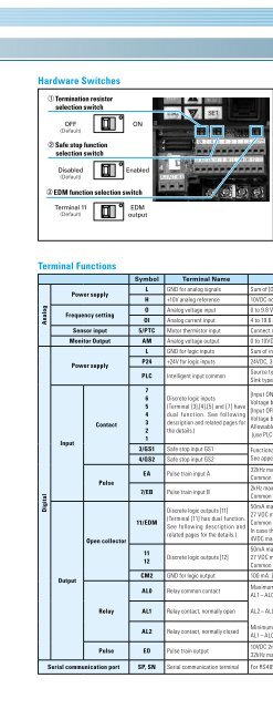
Hardware Switches<br />
a Termination resistor<br />
selection switch<br />
OFF<br />
(Default)<br />
b Safe stop function<br />
selection switch<br />
Disabled<br />
(Default)<br />
c EDM function selection switch<br />
Terminal 11<br />
(Default)<br />
ON<br />
Enabled<br />
EDM<br />
output<br />
Switch Name<br />
a Termination resistor<br />
selection switch<br />
b Safe stop function<br />
selection switch<br />
c EDM function<br />
selection switch<br />
Switch Name Description<br />
Termination resistor for the RS-485<br />
communication port.<br />
<strong>WJ200</strong> has a built-in 200Ω resistor<br />
activated by a DIP switch.<br />
To enable the Safe stop function, set the<br />
DIP switch ON.<br />
Before operating switch, make sure that<br />
the input power supply is off.<br />
To enable the EDM function, set the DIP<br />
switch ON.<br />
Before operating switch, make sure that<br />
the input power supply is off.<br />
Terminal Functions<br />
Analog<br />
Digital<br />
Power supply<br />
Frequency setting<br />
Input<br />
Output<br />
Symbol Terminal Name Description/Ratings<br />
L GND for analog signals Sum of [OI], [O], and [H] currents (return)<br />
H +10V analog reference 10VDC nominal, 10mA max.<br />
O Analog voltage input 0 to 9.8 VDC range, 10 VDC nominal,input impedance 10 kΩ<br />
OI Analog current input 4 to 19.6 mA range, 20 mA nominal, input impedance 100 Ω<br />
Sensor input 5/PTC Motor thermistor input Connect motor thermistor between PTC and L terminal to detect the motor temperature. Set 19 in C005<br />
Monitor Output AM Analog voltage output 0 to 10VDC 2mA max.<br />
Power supply<br />
Contact<br />
Pulse<br />
Open collector<br />
L GND for logic inputs Sum of input [1] – [7] currents (return)<br />
P24 +24V for logic inputs 24VDC, 30mA. (do not short to terminal L)<br />
PLC<br />
7<br />
6<br />
5<br />
4<br />
3<br />
2<br />
1<br />
Intelligent input common<br />
Discrete logic inputs<br />
(Terminal [3],[4],[5] and [7] have<br />
dual function. See following<br />
description and related pages for<br />
the details.)<br />
Source type (connecting [P24] to [1] – [7] turns each input ON).<br />
Sink type (connecting [L] to [1] – [7] makes each input ON.)<br />
[Input ON condition]<br />
Voltage between each terminal and PLC: 18VDC min.<br />
[Input OFF condition]<br />
Voltage between each terminal and PLC: 3VDC max.<br />
Allowable voltage between each terminal and PLC: 27VDC max.<br />
(use PLC or an external supply referenced to terminal L)<br />
3/GS1 Safe stop input GS1 Functionality is based on ISO13849-1<br />
4/GS2 Safe stop input GS2<br />
See appendix for the details.<br />
EA Pulse train input A<br />
32kHz max.<br />
Common is [L]<br />
7/EB Pulse train input B<br />
2kHz max.<br />
Common is [PLC]<br />
11/EDM<br />
11<br />
12<br />
Discrete logic outputs [11]<br />
(Terminal [11] has dual function.<br />
See following description and<br />
related pages for the details.)<br />
Discrete logic outputs [12]<br />
50mA max. ON state current,<br />
27 VDC max. OFF state voltage<br />
Common is CM2<br />
In case the EDM is selected, the functionality is based on ISO13849-1<br />
4VDC max. ON state voltage depression<br />
50mA max. ON state current,<br />
27 VDC max. OFF state voltage<br />
Common is CM2.<br />
CM2 GND for logic output 100 mA: [11], [12] current return<br />
AL0 Relay common contact<br />
Maximum capacity of relays<br />
AL1– AL0:<br />
250VAC, 2A (R load)/ 0.2A (L load)<br />
30VDC, 3A (R load)/ 0.6A (L load)<br />
Relay<br />
AL1 Relay contact, normally open AL2 – AL0:<br />
250VAC, 1A (R load)/ 0.2A (L load)<br />
30VDC, 1A (R load)/ 0.2A (L load)<br />
AL2 Relay contact, normally closed<br />
Minimum capacity of relays<br />
AL1– AL0, AL2 – AL0: 100VAC, 10mA / 5VDC, 100mA<br />
Pulse EO Pulse train output<br />
10VDC 2mA max.<br />
32kHz max.<br />
Serial communication port SP, SN Serial communication terminal For RS485 Modbus communication.<br />
11


