

WJ200 Series Brochure - Hitachi America, Ltd.
WJ200 Series Brochure - Hitachi America, Ltd.
WJ200 Series Brochure - Hitachi America, Ltd.

You also want an ePaper? Increase the reach of your titles
YUMPU automatically turns print PDFs into web optimized ePapers that Google loves.
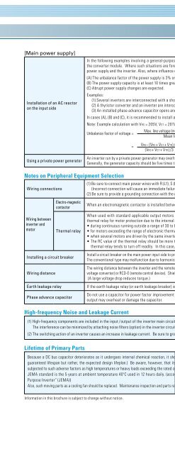
[Main power supply]<br />
Installation of an AC reactor<br />
on the input side<br />
Using a private power generator<br />
In the following examples involving a general-purpose inverter, a large peak current flows on the main power supply side, and is able to destroy<br />
the converter module. Where such situations are foreseen or the connected equipment must be highly reliable, install an AC reactor between the<br />
power supply and the inverter. Also, where influence of indirect lightning strike is possible, install a lightning conductor.<br />
(A) The unbalance factor of the power supply is 3% or higher. (Note)<br />
(B) The power supply capacity is at least 10 times greater than the inverter capacity (the power supply capacity is 500 kVA or more).<br />
(C) Abrupt power supply changes are expected.<br />
Examples:<br />
(1) Several inverters are interconnected with a short bus.<br />
(2) A thyristor converter and an inverter are interconnected with a short bus.<br />
(3) An installed phase advance capacitor opens and closes.<br />
In cases (A), (B) and (C), it is recommended to install an AC reactor on the main power supply side.<br />
Note: Example calculation with VRS = 205V, VST = 201V, VTR = 200V (VRS : R-S line voltage, VST : S-T line voltage, VTR : T-R line voltage)<br />
Max. line voltage (min.) – Mean line voltage<br />
Unbalance factor of voltage = X 100<br />
Mean line voltage<br />
=<br />
VRS− (VRS+ VST+ VTR) /3<br />
X 100 =<br />
205− 202<br />
X 100 = 1.5 (%)<br />
202<br />
(VRS+ VST+ VTR) /3<br />
An inverter run by a private power generator may overheat the generator or suffer from a deformed output voltage waveform of the generator.<br />
Generally, the generator capacity should be five times that of the inverter (kVA) in a PWM control system, or six times greater in a PAM control system.<br />
Notes on Peripheral Equipment Selection<br />
Wiring connections<br />
Wiring between<br />
inverter and<br />
motor<br />
Electro-magnetic<br />
contactor<br />
Thermal relay<br />
Installing a circuit breaker<br />
Wiring distance<br />
Earth leakage relay<br />
Phase advance capacitor<br />
High-frequency Noise and Leakage Current<br />
(1) Be sure to connect main power wires with R (L1), S (L2), and T (L3) terminals (input) and motor wires to U (T1), V (T2), and W (T3) terminals (output).<br />
(Incorrect connection will cause an immediate failure.)<br />
(2) Be sure to provide a grounding connection with the ground terminal ( ).<br />
When an electromagnetic contactor is installed between the inverter and the motor, do not perform on-off switching during running operation.<br />
When used with standard applicable output motors (standard three-phase squirrel-cage four-pole motors), the <strong>WJ200</strong> <strong>Series</strong> does not need a<br />
thermal relay for motor protection due to the internal electronic protective circuit. A thermal relay, however, should be used:<br />
• during continuous running outside a range of 30 to 60 Hz.<br />
• for motors exceeding the range of electronic thermal adjustment (rated current).<br />
• when several motors are driven by the same inverter; install a thermal relay for each motor.<br />
• The RC value of the thermal relay should be more than 1.1 times the rated current of the motor. Where the wiring length is 10 m or more, the<br />
thermal relay tends to turn off readily. In this case, provide an AC reactor on the output side or use a current sensor.<br />
Install a circuit breaker on the main power input side to protect inverter wiring and ensure personal safety. Choose an inverter-compatible circuit breaker.<br />
The conventional type may malfunction due to harmonics from the inverter. For more information, consult the circuit breaker manufacturer.<br />
The wiring distance between the inverter and the remote operator panel should be 20 meters or less. When this distance is exceeded, use CVD-E (currentvoltage<br />
converter) or RCD-E (remote control device). Shielded cable should be used on the wiring. Beware of voltage drops on main circuit wires.<br />
(A large voltage drop reduces torque.)<br />
If the earth leakage relay (or earth leakage breaker) is used, it should have a sensitivity level of 15 mA or more (per inverter).<br />
Do not use a capacitor for power factor improvement between the inverter and the motor because the high-frequency components of the inverter<br />
output may overheat or damage the capacitor.<br />
(1) High-frequency components are included in the input / output of the inverter main circuit, and they may cause interference in a transmitter, radio, or sensor if used near the inverter.<br />
The interference can be minimized by attaching noise filters (option) in the inverter circuitry.<br />
(2) The switching action of an inverter causes an increase in leakage current. Be sure to ground the inverter and the motor.<br />
Lifetime of Primary Parts<br />
Because a DC bus capacitor deteriorates as it undergoes internal chemical reaction, it should normally be replaced every 10 years. (10 years is not the<br />
guaranteed lifespan but rather, the expected design lifeplan.) Be aware, however, that its life expectancy is considerably shorter when the inverter is<br />
subjected to such adverse factors as high temperatures or heavy loads exceeding the rated current of the inverter.<br />
JEMA standard is the 5 years at ambient temperature 40ºC used in 12 hours daily. (according to the “Instructions for Periodic Inspection of General-<br />
Purpose Inverter” (JEMA))<br />
Also, such moving parts as a cooling fan should be replaced. Maintenance inspection and parts replacement must be performed by only specified trained personnel.<br />
Information in this brochure is subject to change without notice.<br />
Ambient temperature (ºC)<br />
50<br />
40<br />
30<br />
2.5 5 10<br />
Capacitor lifetime (years)<br />
27


