Celect (Cummins Electronic Control) & Celect Plus Injector Adjustment
Celect (Cummins Electronic Control) & Celect Plus Injector Adjustment
Celect (Cummins Electronic Control) & Celect Plus Injector Adjustment

You also want an ePaper? Increase the reach of your titles
YUMPU automatically turns print PDFs into web optimized ePapers that Google loves.
<strong>Celect</strong> (<strong>Cummins</strong> <strong>Electronic</strong> <strong>Control</strong>) & <strong>Celect</strong> <strong>Plus</strong> <strong>Injector</strong><br />
<strong>Adjustment</strong><br />
Name: ________________________________<br />
Date: ________________________________<br />
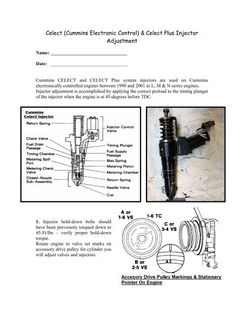
<strong>Cummins</strong> CELECT and CELECT <strong>Plus</strong> system injectors are used on <strong>Cummins</strong><br />
electronically controlled engines between 1990 and 2001 in L, M & N series engines.<br />
<strong>Injector</strong> adjustment is accomplished by applying the correct preload to the timing plunger<br />
of the injector when the engine is at 45-degrees before TDC.<br />
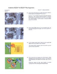
1. <strong>Injector</strong> hold-down bolts should<br />
have been previously torqued down to<br />
45-Ft/lbs – verify proper hold-down<br />
torque.<br />
Rotate engine to valve set marks on<br />
accessory drive pulley for cylinder you<br />
will adjust valves and injectors.
2. Identify the cylinder and correct rocker arms for adjustment.<br />
• There are three housings on an N-14.<br />
• The intake levers are located near the center of the rocker housings and the<br />
exhaust levers closest to the outside of each housing.<br />
• Adjust both valves per specification on engine data plate.<br />
3. The injectors are adjusted at the same time<br />
as the valves. Use the accompanying chart to<br />
determine which cylinder to adjust.<br />
Both valves must be closed on the cylinder<br />
you are adjusting the valves. The rocker<br />
levers will move from side to side.<br />
List the companion cylinder for each of the following cylinders:<br />
1- ___ 2 -___ 3-__- 4-___ 5-___ 6-___<br />
What valve or injectors can be adjusted in each of the following accessory drive<br />
positions<br />
A _______ B______ C______<br />
4. <strong>Injector</strong>s are adjusted using the following method:<br />
• Bottom the injector plunger out three or four times to remove fuel beneath the<br />
timing plunger by tightening and loosening the injector adjustment screw. Do not<br />
tighten more than 25 in-lbs.<br />
• Tighten the adjusting screw to 25 in-lbs.<br />
• Back-out adjusting screw 2 flats or 120 degrees.<br />
• Lock the lock nut.<br />
5. Reinstall engine brake housings and torque to 75 ft-lbs
6. Adjust engine brakes using the dial indicator method.<br />
• Identify the correct slave piston to adjust. All engine brakes are adjusted at the<br />
same time the exhaust valves should be adjusted. So follow the valve and injector<br />
chart again to obtain correct engine position.<br />
• Move slave piston down until it just contacts the exhaust valve bridge.<br />
• Zero-in the dial indicator.<br />
• Back-out the dial indicator to the specification located on the side of the brake<br />
housing.