ZWX Series - TDK-Lambda
ZWX Series - TDK-Lambda
ZWX Series - TDK-Lambda

Create successful ePaper yourself
Turn your PDF publications into a flip-book with our unique Google optimized e-Paper software.
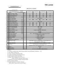
<strong>ZWX</strong> 180, 240, 300<br />
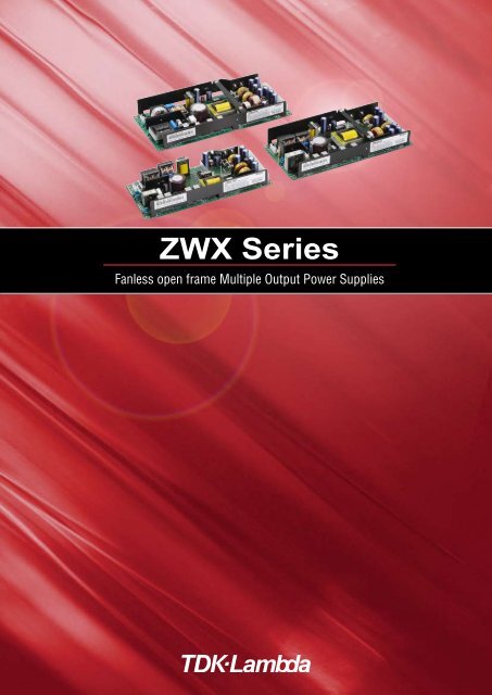
<strong>ZWX</strong> <strong>Series</strong><br />
Fanless open frame Multiple Output Power Supplies<br />
・All specifications are subject to change without notice.
<strong>ZWX</strong> 180, 240, 300<br />
Fanless multiple output power supplies<br />
- ideal for industrial equipment<br />
<strong>ZWX</strong> <strong>Series</strong><br />
Fanless open frame Multiple Output Power Supplies<br />
<strong>ZWX</strong> <strong>Series</strong><br />
・All specifications are subject to change without notice.
<strong>ZWX</strong> 180, 240, 300<br />
Fanless power supplies makes<br />
you free from constraint.<br />
The use of fans in traditional ATX power supplies<br />
restricts system layout and necessitates the use<br />
of forced air cooling. The <strong>ZWX</strong> design guarantees<br />
both operation and performance for<br />
increased flexibility and reliability.<br />
Wide operating temperature for<br />
industrial equipment.<br />
The <strong>ZWX</strong> <strong>Series</strong> can be used in ambient<br />
temperatures from -10°C to + 70°C with operation<br />
at 100% load from -10C to 50C. This specification<br />
is unique to the World's No.1 provider of<br />
industrial power supplies.<br />
Low 36mm profile for mounting<br />
in a 1U rack.<br />
The low profile, open frame format' is able to be<br />
mounted in 1U racks, a desired feature for<br />
industrial equipment. In addition, two further<br />
options will be available in April 2008 - a "L<br />
bracket" and an "enclosed" type bringing further<br />
flexibility to the equipment design.<br />
High efficiency - the proof of<br />
technology.<br />
A 10% efficiency improvement has been obtained<br />
compared to existing products like <strong>Lambda</strong>'s<br />
ZWQ series. An 84% efficiency rating is achieved<br />
by our unique circuit technology (patent pending).<br />
This high efficiency rating enables convection<br />
cooling in a low profile package.<br />
A new format of highly reliable ATX power supplies<br />
Gives you more design freedom<br />
Easy to use and highly reliable<br />
Further flexibility is provided with guaranteed operation<br />
at zero load on any output. Many ATX power supplies<br />
require a minimum load on the main outputs, restricting<br />
operation and wasting power. Output power can be<br />
drawn from a combination of outputs (Wattbox<br />
format) provided the overall ratings are not<br />
exceeded. This feature allows designers to utilize the<br />
power of the <strong>ZWX</strong> series and produce a low<br />
acoustical noise design.<br />
The use of pcb mount connectors on the power<br />
supply rather than a fixed cable harness allows the<br />
output wiring to be tailored to the system design.<br />
High reliability is demanded by industrial equipment<br />
manufacturers and the power supply is critical to the<br />
Product line-up<br />
Model<br />
Condition<br />
Output CH<br />
Output power<br />
Output Voltage<br />
V1 +3.3V<br />
V2 +5V<br />
V3 +12V<br />
V3-2 +12V<br />
V4 -12V<br />
V5 +5V<br />
・All specifications are subject to change without notice.<br />
longevity of the overall equipment. Densei-<strong>Lambda</strong>, the<br />
World's No.1 power supply provider for industrial<br />
equipment, now offers an alternative to the traditional<br />
general purpose ATX power supply.<br />
Model name identification method<br />
<strong>ZWX</strong> 180 /<br />
Option<br />
Blank : Standard type<br />
/L1 : With chassis model<br />
/L2 : With chassis model (reverse)<br />
/A1 : With chassis and cover model<br />
/A2 : With chassis and cover model (reverse)<br />
(Refer to 6-2. Output Derating for details of option model.)<br />
Rated Output Voltage<br />
<strong>Series</strong> Name<br />
<strong>ZWX</strong>180 <strong>ZWX</strong>240 <strong>ZWX</strong>300<br />
Peak Forced air Convection Peak Forced air Convection Peak Forced air Convection<br />
180W 153W 90W 240W 204W 120W 300W 255W 150W<br />
Output Current Output Current Output Current<br />
12.0A 8.4A 6.0A 14.0A 9.8A 7.0A 20.0A 14.0A 10.0A<br />
10.0A 7.0A 5.0A 12.0A 8.4A 6.0A 12.0A 8.4A 6.0A<br />
13.0A 9.0A 6.0A 16.0A 11.2A 8.0A 8.0A 5.6A 4.0A<br />
- - - - - - 16.0A 11.2A 8.0A<br />
0.3A 0.3A 0.2A 0.3A 0.3A 0.2A 0.4A 0.4A 0.2A<br />
2.0A 2.0A 1.4A 2.0A 2.0A 1.4A 2.0A 2.0A 1.4A
<strong>ZWX</strong> 180<br />
<strong>ZWX</strong>180 Specifications<br />
MODEL<br />
<strong>ZWX</strong>180<br />
ITEMS/UNITS<br />
V1 V2 V3 V4 V5 (5VSB)<br />
Voltage Range (*4) V AC85-265<br />
Frequency (*4) Hz 47-63<br />
Power Factor (100/200VAC) typ (*2) 0.99 / 0.93<br />
Input Efficiency (100/200VAC) typ (*2) % 81 / 84<br />
Current (100/200VAC) typ (*2) A 1.9 / 1.0<br />
Inrush Current (100/200VAC) typ (*5) A 14 / 28 at cold start (Ta=25℃ )<br />
Leakage Current (*3)(*11) mA Less than 0.75<br />
Nominal Voltage V +3.3 +5 +12 -12 +5<br />
Minimum Current A 0<br />
Maximum Current (Convection) A 6 5 6 0.2 1.4<br />
Maximum Current (Forced Air) A 8.4 7 9 0.3 2<br />
Maximum Peak Current (*1) A 12 10 13 0.3 2<br />
Maximum Power (Each CH, Convection) W 19.8 25 72 2.4 7<br />
Maximum Power (Convection) W Combined 32W -<br />
Maximum Power (Each CH, Forced Air) W 27.7 35 108 3.6 10<br />
Maximum Power (Forced Air) W Combined 54W -<br />
Maximum Peak Power (Each CH) (*1) W 39.6 50 156 3.6 10<br />
Output Maximum Peak Power (*1) W Combined 63W -<br />
Total Allowable Power (Convection) W 90<br />
Total Allowable Power (Forced Air) W 153<br />
Total Allowable Peak Power (*1) W 180<br />
Voltage Accuracy % ±5<br />
Maximum Line Regulation(*3)(*6)(*7) mV 20 48 20<br />
Maximum Load Regulation(*3)(*6)(*8) mV 100 300 100<br />
Maximum Ripple & Noise (-10℃ 0.32 > 2.1<br />
Over Voltage Protection (*10) V1 : 114%-130% (3.76-4.3V), V2 : 115%-140% (5.74-7V), V3 : 112%-130% (13.4-15.6V)<br />
Function<br />
Remote Sensing<br />
Possible (V1 only)<br />
Remote ON/OFF Control (PS_ON) TTL compatible (H : Output inhibit, L : Output enable) : Designed to meet ATX standard.<br />
Parallel Operation -<br />
<strong>Series</strong> Operation -<br />
Operating Temperature (*12) ℃ -10 to +50 : 100%, 60 : 60%, 70 : 20%<br />
Storage Temperature ℃ -30 to +85<br />
Operating Humidity % RH 30 - 90 (No dewdrop)<br />
Environment Storage Humidity % RH 10 - 95 (No dewdrop)<br />
Vibration<br />
At no operating 10 - 55Hz (sweep for 1min), 19.6 m/s² constant, X, Y, Z 1hour each.<br />
Shock<br />
Less than 392 m/s² at no operating.<br />
Cooling (*12) Convection cooling / forced air cooling (system air cooling) : 0.85 m³/min<br />
Isolation<br />
Withstand Voltage Input-FG : 2kVAC (20mA), Input-Output : 3kVAC (20mA), Output-FG : 500VAC (100mA) for 1min.<br />
Isolation Resistance<br />
More than 100M Ω at 25℃ and 70%RH Output-FG : 500VDC<br />
Safety<br />
Approved by UL60950-1, CSA60950-1, EN60950-1, EN50178 (OV II),<br />
Designed to meet DENAN (Section 2) at 100VAC only.<br />
Standards PFHC<br />
Designed to meet IEC61000-3-2<br />
EMI (*3) EN55011/EN55022-B, FCC-ClassB, VCCI-B<br />
Immunity Designed to meet IEC61000-4-2, -3, -4, -5, -6, -8, -11<br />
Mechanical<br />
Weight typ g 500<br />
Size (W x H x D) mm 94 x 36 x 210 (Refer to outline drawing)<br />
<br />
・All specifications are subject to change without notice.
<strong>ZWX</strong> 180<br />
(*1) Operating time at peak output is less than 5sec.<br />
(Average output power and current are less than maximum output power and current.)<br />
(*2) At total output power (Forced air) (V1=6.5A, V2=6.5A, V3=7.7A, V4=0.2A, V5=1.0A), Ta=25℃.<br />
(*3) At total output power (Forced air).<br />
(*4) For cases where conformance to various safety specs (UL, CSA, EN) are required, to be described as 100 - 240VAC (50/60Hz).<br />
(*5) Not applicable for the inrush current to Noise Filter for less than 0.2ms.<br />
(*6) Please refer to Fig. A for measurement of line & load regulation and ripple voltage.<br />
(*7) 85 - 265VAC, constant load.<br />
(*8) No load-Full load, constant input voltage.<br />
(*9) Avoid to operate at overload or short circuit condition for more than 30 seconds.<br />
V1, V2, V3 : OCP circuit will shut down output except V5 with delay (more than 5s), manual reset (PS_ON reset or re power on).<br />
V4 : Constant current limit with automatic recovery.<br />
V5 : Constant current limit in conjunction with all output with automatic recovery.<br />
(*10) OVP circuit will shut down output, manual reset (PS_ON reset or re power on).<br />
(*11) Measured by the each measuring method of UL, CSA, EN and DENAN (at 60Hz), Ta=25℃.<br />
(*12) At forced air cooling, standard mounting. Refer to output derating curve.<br />
P.S.<br />
3.3V sense<br />
V1<br />
150mm<br />
AWG18×N<br />
Measuring Point<br />
for Ripple & Noise.<br />
A<br />
C1<br />
C6<br />
LOAD1<br />
COM<br />
V2<br />
A<br />
C2<br />
C7<br />
LOAD2<br />
COM<br />
V3<br />
A<br />
C3<br />
C8<br />
LOAD3<br />
COM<br />
COM<br />
A<br />
C4<br />
C9<br />
LOAD4<br />
V4<br />
V5<br />
A<br />
C5<br />
C10<br />
LOAD5<br />
COM<br />
PS_ON<br />
Measuring Point for<br />
Vo and Line/Load Regulation.<br />
COM<br />
Measure with JEITA RC-9131 probe.<br />
Bandwidth of scope : 100MHz<br />
Capacitance<br />
C1, C2, C3, C4, C5 : Film Cap. 0.1 uF<br />
C6, C7, C8, C9, C10 : Elec. Cap. 100 uF<br />
Fig.A<br />
・All specifications are subject to change without notice.
<strong>ZWX</strong> 180<br />
<strong>ZWX</strong>180 Output Derating<br />
OUTPUT DERATING CURVE (Convection Cooling)<br />
120<br />
100<br />
80<br />
MOUNTING A<br />
LOAD (%)<br />
60<br />
MOUNTING B-E<br />
40<br />
20<br />
0<br />
-10 0 10 20 30 40 50 60 70 80<br />
Ta (°C)<br />
OUTPUT DERATING CURVE (Forced Air Cooling)<br />
120<br />
100<br />
80<br />
LOAD (%)<br />
60<br />
MOUNTING -E<br />
40<br />
20<br />
0<br />
-10 0 10 20 30 40 50 60 70 80<br />
Ta (°C)<br />
MOUNTING A<br />
MOUNTING B<br />
MOUNTING C<br />
MOUNTING D<br />
MOUNTING E<br />
DON'T USE<br />
(STANDARD MOUNTING)<br />
CN1 (INPUT)<br />
CN1<br />
CN1<br />
CN1<br />
CN1<br />
CN1<br />
<br />
・All specifications are subject to change without notice.
<strong>ZWX</strong> 180<br />
<strong>ZWX</strong>180 Outline Drawing<br />
36±1<br />
210±1<br />
4-See Note A<br />
N<br />
L<br />
See Note D<br />
(73)<br />
(11)<br />
5<br />
3<br />
1<br />
CN1<br />
COMPONENT SIDE<br />
CN41<br />
1<br />
2<br />
CN31 11 22<br />
10 21<br />
9 20<br />
8 19<br />
7 18<br />
6 17<br />
5 16<br />
4 15<br />
3 14<br />
2 13<br />
1 12<br />
CN21<br />
5 10<br />
4 9<br />
3 8<br />
2 7<br />
1 6<br />
21.6)<br />
57.7)<br />
87.7)<br />
84±0.5<br />
94±1<br />
LEAD CUT<br />
LESS THAN 3mm<br />
5<br />
200±0.5<br />
NAME PLATE<br />
(7.5)<br />
5<br />
<strong>ZWX</strong>180<br />
INPUT : 100-240VAC 2.3A (2.7Amax@Peak Power) 50 / 60Hz<br />
OUTPUT :<br />
Voltage +3.3V +5V +12V -12V +5VSB<br />
MAX Current 8.4A 7.0A 9.0A 0.3A 2.0A Total<br />
Power 54W 108W 3.6W 10W 153W<br />
PEAK Current 12A 10A 13A 0.3A 2.0A Total<br />
Power 63W 156W 3.6W 10W 180W<br />
BAR CODE<br />
Refer to www.densei-lambda.com<br />
for installation instructions.<br />
See Note C<br />
MADE IN JAPAN<br />
Various safety mark will be indicated<br />
See Note B<br />
NOTES<br />
A : 4-φ3.5 holes are for customer’s chassis mounting holes.<br />
All must be screwed in order to conform the vibration/EMI spec.<br />
To keep the distance more than 5mm between PCB edge and<br />
customer’s chassis.<br />
B : Model name, input voltage range, nominal output voltage, maximum<br />
output current and peak output current are shown here<br />
in accordance with the specifications.<br />
C : Country of manufacture wii be shown here.<br />
D : is for safety ground connection.<br />
CONNECTORS USED:<br />
PART DESCRIPTION PART NAME MANUFACT.<br />
PIN HEADER (INPUT SIDE CN1) B3P5-VH(LF)(SN) J.S.T.<br />
PIN HEADER (OUTPUT SIDE CN21) 5566-10A-210 MOLEX<br />
PIN HEADER (OUTPUT SIDE CN31) 5566-22A-210 MOLEX<br />
PIN HEADER (OUTPUT SIDE CN41) B2B-XH-AM(LF)(SN) J.S.T.<br />
*OUTPUT CURRENT OF EACH CONNECTOR PIN MUST BE LESS THAN 9A.<br />
MATCHING HOUSINGS, PINS & TOOL (NOT INCLUDED WITH THE PRODUCT):<br />
PART DESCRIPTION PART NAME MANUFACT.<br />
SOCKET HOUSING (CN1) VHR-5N J.S.T.<br />
SOCKET HOUSING (CN21) 5557-10R-210 MOLEX<br />
SOCKET HOUSING (CN31) 5557-22R-210 MOLEX<br />
SOCKET HOUSING (CN41) XHP-2 J.S.T.<br />
TERMINAL PINS (CN1)<br />
SVH-21T-P1.1<br />
BVH-21T-P1.1<br />
J.S.T.<br />
TERMINAL PINS (CN21, CN31) 5556PBT, 5556PBTL MOLEX<br />
TERMINAL PINS (CN41)<br />
BXH-001T-P0.6<br />
SXH-001T-P0.6<br />
J.S.T.<br />
HAND CRIMPING TOOL (CN1) YC-160R J.S.T.<br />
HAND CRIMPING TOOL AWG #18~#24 57027-5000<br />
(CN21, CN3)<br />
AWG #22~#28 57064-5000<br />
MOLEX<br />
HAND CRIMPING TOOL (CN41)<br />
YC-110R<br />
YRS-110<br />
J.S.T.<br />
CN PIN ASSIGN<br />
CN21<br />
PIN NO. FUNCTION PIN NO. FUNCTION<br />
5 +12V 10 +12V<br />
4 COM 9 COM<br />
3 COM 8 COM<br />
2 +5V 7 +5V<br />
1 +3.3V 6 N.C.<br />
CN31<br />
PIN NO. FUNCTION PIN NO. FUNCTION<br />
11 +5V SB 22 +5V<br />
10 +5V 21 +5V<br />
9 +5V 20 +5V<br />
CN41<br />
8 COM 19 COM<br />
7 COM 18 COM<br />
6 -12V 17 COM<br />
5 +3.3V sense 16 COM<br />
4 +3.3V 15 +3.3V<br />
3 +3.3V 14 +3.3V<br />
2 COM 13 COM<br />
1 +12V 12 +12V<br />
PIN NO.<br />
1 PWR_OK<br />
2 PS_ON<br />
FUNCTION<br />
・All specifications are subject to change without notice.
<strong>ZWX</strong> 240<br />
<strong>ZWX</strong>240 Specifications<br />
MODEL<br />
<strong>ZWX</strong>240<br />
ITEMS/UNITS<br />
V1 V2 V3 V4 V5 (5VSB)<br />
Voltage Range (*4) V AC85-265<br />
Frequency (*4) Hz 47-63<br />
Power Factor (100/200VAC) typ (*2) 0.99 / 0.93<br />
Input Efficiency (100/200VAC) typ (*2) % 81/ 84<br />
Current (100/200VAC) typ (*2) A 2.6 / 1.3<br />
Inrush Current (100/200VAC) typ (*5) A 14 / 28 at cold start (Ta=25℃ )<br />
Leakage Current (*3)(*11) mA Less than 0.75<br />
Nominal Voltage V +3.3 +5 +12 -12 +5<br />
Minimum Current A 0<br />
Maximum Current (Convection) A 7 6 8 0.2 1.4<br />
Maximum Current (Forced Air) A 9.8 8.4 11.2 0.3 2<br />
Maximum Peak Current (*1) A 14 12 16 0.3 2<br />
Maximum Power (Each CH, Convection) W 23.1 30 96 2.4 7<br />
Maximum Power (Each CH) W 32.3 42 134.4 3.6 10<br />
Maximum Peak Power (Each CH)(*1) W 46.2 60 192 3.6 10<br />
Output<br />
Total Allowable Power (Convection) W 120<br />
Total Allowable Power (Forced Air) W 204<br />
Total Allowable Peak Power (*1) W 240<br />
Voltage Accuracy % ±5<br />
Maximum Line Regulation(*3)(*6)(*7) mV 20 48 20<br />
Maximum Load Regulation(*3)(*6)(*8) mV 100 300 100<br />
Maximum Ripple & Noise (-10℃ 0.32 > 2.1<br />
Over Voltage Protection (*10) V1 : 114%-130% (3.76-4.3V), V2 : 115%-140% (5.74-7V), V3 : 112%-130% (13.4-15.6V)<br />
Function<br />
Remote Sensing<br />
Possible (V1 only)<br />
Remote ON/OFF Control (PS_ON) TTL compatible (H : Output inhibit, L : Output enable) : Designed to meet ATX standard.<br />
Parallel Operation -<br />
<strong>Series</strong> Operation -<br />
Operating Temperature (*12) ℃ -10 to +50 : 100%, 60 : 60%, 70 : 20%<br />
Storage Temperature ℃ -30 to +85<br />
Operating Humidity % RH 30 - 90 (No dewdrop)<br />
Environment Storage Humidity % RH 10 - 95 (No dewdrop)<br />
Vibration<br />
At no operating 10 - 55Hz (sweep for 1min.) 19.6m/s² constant, X, Y, Z 1hour each.<br />
Shock<br />
Less than 392m/s² at no operating.<br />
Cooling (*12) Convection cooling / forced air cooling (system air cooling) : 0.85m³/min<br />
Isolation<br />
Withstand Voltage Input-FG : 2kVAC(20mA), Input-Output : 3kVAC(20mA), Output-FG : 500VAC(100mA) for 1min.<br />
Isolation Resistance<br />
More than 100M Ω at 25℃ and 70%RH Output-FG : 500VDC<br />
Safety<br />
Approved by UL60950-1, CSA60950-1, EN60950-1, EN50178 (OV II),<br />
Designed to meet DENAN (Section 2) at 100VAC only.<br />
Standards PFHC<br />
Designed to meet IEC61000-3-2<br />
EMI (*3) EN55011/EN55022-B, FCC-ClassB, VCCI-B<br />
Immunity Designed to meet IEC61000-4-2, -3, -4, -5, -6, -8, -11<br />
Mechanical<br />
Weight typ g 650<br />
Size (W x H x D) mm 106 x 36 x 225 (Refer to outline drawing)<br />
<br />
・All specifications are subject to change without notice.
<strong>ZWX</strong> 240<br />
(*1) Operating time at peak output is less than 5sec.<br />
(Average output power and current are less than maximum output power and current.)<br />
(*2) At total output power (Forced air) (V1=9.0A, V2=8.0A, V3=10.6A, V4=0.2A, V5=1.0A), Ta=25℃.<br />
(*3) At total output power (Forced air).<br />
(*4) For cases where conformance to various safety specs (UL, CSA, EN) are required, to be described as 100 - 240VAC (50/60Hz).<br />
(*5) Not applicable for the inrush current to Noise Filter for less than 0.2ms.<br />
(*6) Please refer to Fig. A for measurement of line & load regulation and ripple voltage.<br />
(*7) 85 - 265VAC, constant load.<br />
(*8) No load-Full load, constant input voltage.<br />
(*9) Avoid to operate at overload or short circuit condition for more than 30 seconds.<br />
V1, V2, V3 : OCP circuit will shut down output except V5 with delay (more than 5s), manual reset (PS_ON reset or re power on).<br />
V4 : Constant current limit with automatic recovery.<br />
V5 : Constant current limit in conjunction with all output with automatic recovery.<br />
(*10) OVP circuit will shut down output, manual reset (PS_ON reset or re power on).<br />
(*11) Measured by the each measuring method of UL, CSA, EN and DENAN (at 60Hz), Ta=25℃.<br />
(*12) At forced air cooling, standard mounting. Refer to output derating curve.<br />
P.S.<br />
3.3V sense<br />
V1<br />
150mm<br />
AWG18×N<br />
Measuring Point<br />
for Ripple & Noise.<br />
A<br />
C1<br />
C6<br />
LOAD1<br />
COM<br />
V2<br />
A<br />
C2<br />
C7<br />
LOAD2<br />
COM<br />
V3<br />
A<br />
C3<br />
C8<br />
LOAD3<br />
COM<br />
COM<br />
A<br />
C4<br />
C9<br />
LOAD4<br />
V4<br />
V5<br />
A<br />
C5<br />
C10<br />
LOAD5<br />
COM<br />
PS_ON<br />
Measuring Point for<br />
Vo and Line/Load Regulation.<br />
COM<br />
Measure with JEITA RC-9131 probe.<br />
Bandwidth of scope : 100MHz<br />
Capacitance<br />
C1, C2, C3, C4, C5 : Film Cap. 0.1 uF<br />
C6, C7, C8, C9, C10 : Elec. Cap. 100 uF<br />
Fig.A<br />
・All specifications are subject to change without notice.
<strong>ZWX</strong> 240<br />
<strong>ZWX</strong>240 Output Derating<br />
OUTPUT DERATING CURVE (Convection Cooling)<br />
120<br />
100<br />
80<br />
MOUNTING A<br />
LOAD (%)<br />
60<br />
MOUNTING B-E<br />
40<br />
20<br />
0<br />
-10 0 10 20 30 40 50 60 70 80<br />
Ta (°C)<br />
OUTPUT DERATING CURVE (Forced Air Cooling)<br />
120<br />
100<br />
80<br />
LOAD (%)<br />
60<br />
MOUNTING -E<br />
40<br />
20<br />
0<br />
-10 0 10 20 30 40 50 60 70 80<br />
Ta (°C)<br />
MOUNTING A<br />
MOUNTING B<br />
MOUNTING C<br />
MOUNTING D<br />
MOUNTING E<br />
DON'T USE<br />
(STANDARD MOUNTING)<br />
CN1 (INPUT)<br />
CN1<br />
CN1<br />
CN1<br />
CN1<br />
CN1<br />
10 ・All specifications are subject to change without notice.
<strong>ZWX</strong> 240<br />
<strong>ZWX</strong>240 Outline Drawing<br />
36±1<br />
225±1<br />
4-See Note A<br />
N<br />
L<br />
See Note D<br />
(84)<br />
(11)<br />
5 CN1<br />
3<br />
1<br />
COMPONENT SIDE<br />
CN41 1<br />
2<br />
CN31 11 22<br />
10 21<br />
9 20<br />
8 19<br />
7 18<br />
6 17<br />
5 16<br />
4 15<br />
3 14<br />
2 13<br />
1 12<br />
CN21 5 10<br />
4 9<br />
3 8<br />
2 7<br />
1 6<br />
<br />
59.1)<br />
88.3)<br />
96±0.5<br />
106±1<br />
LEAD CUT<br />
LESS THAN 3mm<br />
5<br />
215±0.5<br />
NAME PLATE (8)<br />
5<br />
<strong>ZWX</strong>240<br />
INPUT : 100-240VAC 3.0A (3.6Amax@Peak Power) 50 / 60Hz<br />
OUTPUT :<br />
Voltage +3.3V +5V +12V -12V +5VSB<br />
MAX Current 9.8A 8.4A 11.2A 0.3A 2.0A Total<br />
Power 32.3W 42.0W 134.4W 3.6W 10.0W 204W<br />
PEAK Current 14.0A 12.0A 16.0A 0.3A 2.0A Total<br />
Power 46.2W 60.0W 192.0W 3.6W 10.0W 240W<br />
BAR CODE<br />
Refer to www.densei-lambda.com<br />
for installation instructions.<br />
See Note C<br />
MADE IN JAPAN<br />
Various safety mark<br />
will be indicated<br />
See Note B<br />
NOTES<br />
A : 4-φ3.5 holes are for customer’s chassis mounting holes.<br />
All must be screwed in order to conform the vibration/EMI spec.<br />
B : Model name, input voltage range, nominal output voltage,<br />
maximum output current and peak output current are shown<br />
here in accordance with the specifications.<br />
C : Country of manufacture wii be shown here.<br />
D : is for safety ground connection.<br />
CONNECTORS USED:<br />
PART DESCRIPTION PART NAME MANUFACT.<br />
PIN HEADER (INPUT SIDE CN1) B3P5-VH(LF)(SN) J.S.T.<br />
PIN HEADER (OUTPUT SIDE CN21) 5566-10A-210 MOLEX<br />
PIN HEADER (OUTPUT SIDE CN31) 5566-22A-210 MOLEX<br />
PIN HEADER (OUTPUT SIDE CN41) B2B-XH-AM(LF)(SN) J.S.T.<br />
*OUTPUT CURRENT OF EACH CONNECTOR PIN MUST BE LESS THAN 9A.<br />
MATCHING HOUSINGS, PINS & TOOL (NOT INCLUDED WITH THE PRODUCT):<br />
PART DESCRIPTION PART NAME MANUFACT.<br />
SOCKET HOUSING (CN1) VHR-5N J.S.T.<br />
SOCKET HOUSING (CN21) 5557-10R-210 MOLEX<br />
SOCKET HOUSING (CN31) 5557-22R-210 MOLEX<br />
SOCKET HOUSING (CN41) XHP-2 J.S.T.<br />
TERMINAL PINS (CN1)<br />
SVH-21T-P1.1<br />
BVH-21T-P1.1<br />
J.S.T.<br />
TERMINAL PINS (CN21, CN31) 5556PBT, 5556PBTL MOLEX<br />
TERMINAL PINS (CN41)<br />
BXH-001T-P0.6<br />
SXH-001T-P0.6<br />
J.S.T.<br />
HAND CRIMPING TOOL (CN1) YC-160R J.S.T.<br />
HAND CRIMPING TOOL AWG #18~#24 57027-5000<br />
(CN21, CN31)<br />
AWG #22~#28 57064-5000<br />
MOLEX<br />
HAND CRIMPING TOOL (CN41)<br />
YC-110R<br />
YRS-110<br />
J.S.T.<br />
CN PIN ASSIGN<br />
CN21<br />
PIN NO. FUNCTION PIN NO. FUNCTION<br />
5 +12V 10 +12V<br />
4 COM 9 COM<br />
3 COM 8 COM<br />
2 +5V 7 +5V<br />
1 +3.3V 6 N.C.<br />
CN31<br />
PIN NO. FUNCTION PIN NO. FUNCTION<br />
11 +5V SB 22 +5V<br />
10 +5V 21 +5V<br />
9 +5V 20 +5V<br />
CN41<br />
8 COM 19 COM<br />
7 COM 18 COM<br />
6 -12V 17 COM<br />
5 +3.3V sense 16 COM<br />
4 +3.3V 15 +3.3V<br />
3 +3.3V 14 +3.3V<br />
2 COM 13 COM<br />
1 +12V 12 +12V<br />
PIN NO.<br />
1 PWR_OK<br />
2 PS_ON<br />
FUNCTION<br />
・All specifications are subject to change without notice.<br />
11
<strong>ZWX</strong> 300<br />
<strong>ZWX</strong>300 Specifications<br />
MODEL<br />
<strong>ZWX</strong>300<br />
ITEMS/UNITS<br />
V1 V2 V3-1 V3-2 V4 V5 (5VSB)<br />
Voltage Range (*4) V AC85-265<br />
Frequency Hz 47-63<br />
Power Factor (100/200VAC) typ (*2) 0.99 / 0.93<br />
Input Efficiency (100/200VAC) typ (*2) % 81 / 84<br />
Current (100/200VAC) typ (*2) A 3.2 / 1.6<br />
Inrush Current (100/200VAC) typ (*5) A 14 / 28 at cold start (Ta=25℃ )<br />
Leakage Current (*3)(*11) mA Less than 0.75<br />
Nominal Voltage V +3.3 +5 +12 -12 +5<br />
Minimum Current A 0<br />
Maximum Current (Convection) A 10 6 4 8 0.2 1.4<br />
Maximum Current (Forced Air) A 14 8.4 5.6 11.2 0.4 2<br />
Maximum Peak Current (*1) A 20 12 8 16 0.4 2<br />
Maximum Power (Each CH, Convection) W 33 30 48 96 2.4 7<br />
Maximum Power (Convection) W - Combined 131W -<br />
Maximum Power (Each CH,Forced Air) W 46.2 42 67.2 134.4 4.8 10<br />
Maximum Peak Power (Each CH)(*1) W 66 60 96 192 4.8 10<br />
Output<br />
Function<br />
Environment<br />
Isolation<br />
Standards<br />
Mechanical<br />
Maximum Peak Power (*1) W - Combined 264W -<br />
Total Allowable Power (Convection) W 150<br />
Total Allowable Power (Forced Air) W 255<br />
Total Allowable Peak Power (*1) W 300<br />
Voltage Accuracy % ±5<br />
Maximum Line Regulation(*3)(*6)(*7) mV 20 48 20<br />
Maximum Load Regulation(*3)(*6)(*8) mV 100 300 100<br />
Maximum Ripple & Noise (-10℃ 11.8 > 0.42 > 2.1<br />
Over Voltage Protection (*10) V1 : 114%-130% (3.76-4.3V), V2 : 115%-140% (5.74-7V), V3-1, V3-2 : 112%-130% (13.4-15.6V)<br />
Remote Sensing<br />
Possible (V1 only)<br />
Remote ON/OFF Control (PS_ON) TTL compatible (H : Output inhibit, L : Output enable) : Designed to meet ATX standard.<br />
Parallel Operation -<br />
<strong>Series</strong> Operation -<br />
Operating Temperature (*12) ℃ -10 to +50 : 100%, 60 : 60%, 70 : 20%<br />
Storage Temperature ℃ -30 to +85<br />
Operating Humidity % RH 30 - 90 (No dewdrop)<br />
Storage Humidity % RH 10 - 95 (No dewdrop)<br />
Vibration<br />
At no operating 10 - 55Hz (sweep for 1min), 19.6 m/s² constant, X, Y, Z 1hour each.<br />
Shock<br />
Less than 392 m/s² at no operating.<br />
Cooling (*12) Convection cooling / forced air cooling (system air cooling) : 0.85 m³/min<br />
Withstand Voltage Input-FG : 2kVAC (20mA), Input-Output : 3kVAC (20mA), Output-FG : 500VAC (100mA) for 1min.<br />
Isolation Resistance<br />
More than 100M Ω at 25℃ and 70%RH Output-FG : 500VDC<br />
Safety<br />
Approved by UL60950-1, CSA60950-1, EN60950-1, EN50178 (OV II),<br />
Designed to meet DENAN (Section 2) at 100VAC only.<br />
PFHC<br />
Designed to meet IEC61000-3-2<br />
EMI (*3) EN55011/EN55022-B, FCC-ClassB, VCCI-B<br />
Immunity Designed to meet IEC61000-4-2, -3, -4, -5, -6, -8, -11<br />
Weight typ g 800<br />
Size (W x H x D) mm 118 x 36 x 250 (Refer to outline drawing)<br />
12 ・All specifications are subject to change without notice.
<strong>ZWX</strong> 300<br />
(*1) Operating time at peak output is less than 5sec.<br />
(Average output power and current are less than maximum output power and current.)<br />
(*2) At total output power (Forced air) (V1=12A, V2=7.0A, V3-1=5.0A, V3-2=9.4A, V4=0.2A, V5=1.0A), Ta=25℃.<br />
(*3) At total output power (Forced air).<br />
(*4) For cases where conformance to various safety specs (UL, CSA, EN) are required, to be described as 100 - 240VAC (50/60Hz).<br />
(*5) Not applicable for the inrush current to Noise Filter for less than 0.2ms.<br />
(*6) Please refer to Fig. A for measurement of line & load regulation and ripple voltage.<br />
(*7) 85 - 265VAC, constant load.<br />
(*8) No load-Full load, constant input voltage.<br />
(*9) Avoid to operate at overload or short circuit condition for more than 30 seconds.<br />
V1, V2, V3-1 and V3-2 : OCP circuit will shut down output except V5 with delay (more than 5s), manual reset (PS_ON reset or re power on).<br />
V4 : Constant current limit with automatic recovery.<br />
V5 : Constant current limit in conjunction with all output with automatic recovery.<br />
(*10) OVP circuit will shut down output, manual reset (PS_ON reset or re power on).<br />
(*11) Measured by the each measuring method of UL, CSA, EN and DENAN (at 60Hz), Ta=25℃.<br />
(*12) At forced air cooling, standard mounting. Refer to output derating curve.<br />
P.S.<br />
3.3V sense<br />
V1<br />
150mm<br />
AWG18×N<br />
Measuring Point<br />
for Ripple & Noise.<br />
A<br />
C1<br />
C7<br />
LOAD1<br />
COM<br />
V2<br />
A<br />
C2<br />
C8<br />
LOAD2<br />
COM<br />
V3-1<br />
A<br />
C3<br />
C9<br />
LOAD3<br />
COM<br />
V3-2<br />
A<br />
C4<br />
C10<br />
LOAD4<br />
COM<br />
COM<br />
A<br />
C5<br />
C11<br />
LOAD5<br />
V4<br />
V5<br />
A<br />
C6<br />
C12<br />
LOAD6<br />
COM<br />
PS_ON<br />
Measuring Point for<br />
Vo and Line/Load Regulation.<br />
COM<br />
Measure with JEITA RC-9131 probe.<br />
Bandwidth of scope : 100MHz<br />
Capacitance<br />
C1, C2, C3, C4, C5, C6 : Film Cap. 0.1 μF<br />
C7, C8, C9, C10, C11, C12 : Elec. Cap. 100 μF<br />
Fig.A<br />
・All specifications are subject to change without notice.<br />
13
<strong>ZWX</strong> 300<br />
<strong>ZWX</strong>300 Output Derating<br />
OUTPUT DERATING CURVE (Convection Cooling)<br />
120<br />
100<br />
80<br />
MOUNTING A<br />
LOAD (%)<br />
60<br />
MOUNTING B-E<br />
40<br />
20<br />
0<br />
-10 0 10 20 30 40 50 60 70 80<br />
Ta (°C)<br />
OUTPUT DERATING CURVE (Forced Air Cooling)<br />
120<br />
100<br />
80<br />
LOAD (%)<br />
60<br />
MOUNTING -E<br />
40<br />
20<br />
0<br />
-10 0 10 20 30 40 50 60 70 80<br />
Ta (°C)<br />
MOUNTING A<br />
MOUNTING B<br />
MOUNTING C<br />
MOUNTING D<br />
MOUNTING E<br />
DON'T USE<br />
(STANDARD MOUNTING)<br />
CN1 (INPUT)<br />
CN1<br />
CN1<br />
CN1<br />
CN1<br />
CN1<br />
14 ・All specifications are subject to change without notice.
<strong>ZWX</strong> 300<br />
<strong>ZWX</strong>300 Outline Drawing<br />
36±1.5<br />
250±1<br />
4-See Note A<br />
N<br />
L<br />
See Note D<br />
(95.5)<br />
(11)<br />
5<br />
3 CN1<br />
1<br />
COMPONENT SIDE<br />
1<br />
CN41 2<br />
CN31 1122<br />
10 21<br />
9876 20<br />
19<br />
18<br />
17<br />
5 16<br />
4 15<br />
321 14<br />
13<br />
12<br />
CN21 5 10<br />
4 9876<br />
3<br />
2<br />
1<br />
CN51 2 4<br />
1 3<br />
(35.9)<br />
19<br />
(72)<br />
(100.8)<br />
108±0.5<br />
118±1<br />
LEAD CUT<br />
LESS THAN 3mm<br />
5<br />
240±0.5<br />
NAME PLATE<br />
(8)<br />
5<br />
<strong>ZWX</strong>300<br />
INPUT : 100-240VAC 3.8A (4.5Amax@Peak Power) 50 / 60Hz<br />
OUTPUT :<br />
Voltage +3.3V +5V +12V1 +12V2 -12V +5VSB<br />
MAX Current 14.0A 8.4A 5.6A 11.2A 0.4A 2.0A Total<br />
Power 46.2W 42.0W 67.2W 134.4W 4.8W 10.0W 255W<br />
PEAK Current 20.0A 12.0A 8.0A 16.0A 0.4A 2.0A Total<br />
Power 66.0W 60.0W 264.0W 4.8W 10.0W 300W<br />
See Note C<br />
BAR CODE<br />
Refer to www.densei-lambda.com<br />
for installation instructions.<br />
MADE IN JAPAN<br />
Various safety mark<br />
will be indicated<br />
See Note B<br />
NOTES<br />
A : 4-φ3.5 holes are for customer’s chassis mounting holes.<br />
All must be screwed in order to conform the vibration/EMI spec.<br />
B : Model name, input voltage range, nominal output voltage,<br />
maximum output current and peak output current are shown<br />
here in accordance with the specifications.<br />
C : Country of manufacture wii be shown here.<br />
D : is for safety ground connection.<br />
CONNECTORS USED:<br />
PART DESCRIPTION PART NAME MANUFACT.<br />
PIN HEADER (INPUT SIDE CN1) B3P5-VH(LF)(SN) J.S.T.<br />
PIN HEADER (OUTPUT SIDE CN21) 5566-10A-210 MOLEX<br />
PIN HEADER (OUTPUT SIDE CN31) 5566-22A-210 MOLEX<br />
PIN HEADER (OUTPUT SIDE CN41) B2B-XH-AM(LF)(SN) J.S.T.<br />
PIN HEADER (OUTPUT SIDE CN51) 5566-04A-210 MOLEX<br />
*OUTPUT CURRENT OF EACH CONNECTOR PIN MUST BE LESS THAN 9A.<br />
MATCHING HOUSINGS, PINS & TOOL (NOT INCLUDED WITH THE PRODUCT):<br />
PART DESCRIPTION PART NAME MANUFACT.<br />
SOCKET HOUSING (CN1) VHR-5N J.S.T.<br />
SOCKET HOUSING (CN21) 5557-10R-210 MOLEX<br />
SOCKET HOUSING (CN31) 5557-22R-210 MOLEX<br />
SOCKET HOUSING (CN41) XHP-2 J.S.T.<br />
SOCKET HOUSING (CN51) 5557-04R-210 MOLEX<br />
TERMINAL PINS (CN1)<br />
SVH-21T-P1.1<br />
BVH-21T-P1.1<br />
J.S.T.<br />
TERMINAL PINS (CN41)<br />
BXH-001T-P0.6<br />
SXH-001T-P0.6<br />
J.S.T.<br />
TERMINAL PINS (CN21, CN31, CN51) 5556PBT, 5556PBTL MOLEX<br />
HAND CRIMPING TOOL (CN1) YC-160R J.S.T.<br />
HAND CRIMPING TOOL (CN41)<br />
YC-110R<br />
YRS-110<br />
J.S.T.<br />
HAND CRIMPING TOOL AWG #18~#24 57027-5000<br />
(CN21, CN31, CN51) AWG #22~#28 57064-5000<br />
MOLEX<br />
CN PIN ASSIGN<br />
CN21<br />
PIN NO. FUNCTION PIN NO. FUNCTION<br />
5 +12V-1 10 +12V-1<br />
4 COM 9 COM<br />
3 COM 8 COM<br />
2 +5V 7 +5V<br />
1 +3.3V 6 N.C.<br />
CN31<br />
PIN NO. FUNCTION PIN NO. FUNCTION<br />
11 +5V SB 22 +5V<br />
10 +5V 21 +5V<br />
9 +5V 20 +5V<br />
CN41<br />
8 COM 19 COM<br />
7 COM 18 COM<br />
6 -12V 17 COM<br />
5 +3.3V sense 16 COM<br />
4 +3.3V 15 +3.3V<br />
3 +3.3V 14 +3.3V<br />
2 COM 13 COM<br />
1 +12V-1 12 +12V-1<br />
PIN NO.<br />
1 PWR_OK<br />
2 PS_ON<br />
CN51<br />
FUNCTION<br />
PIN NO. FUNCTION PIN NO. FUNCTION<br />
2 COM 4 +12V-2<br />
1 COM 3 +12V-2<br />
・All specifications are subject to change without notice.<br />
15
<strong>ZWX</strong> 180, 240, 300<br />
Block Diagram<br />
3 Terminal<br />
Regulator<br />
-12V<br />
COM<br />
Input<br />
85~<br />
265VAC<br />
L<br />
N<br />
Fuse<br />
Line<br />
filter<br />
Rectifier<br />
PFHC<br />
Circuit<br />
Inrush<br />
Current<br />
limiting<br />
Smoothing<br />
Filter<br />
Switching<br />
Circuit<br />
Rectifier &<br />
Smoothing<br />
Filter<br />
Control<br />
Circuit<br />
Output<br />
Sensing<br />
+5V<br />
COM<br />
+3.3V sense<br />
Control<br />
Circuit<br />
Rectifier &<br />
Smoothing<br />
Filter<br />
+3.3V<br />
Primary OCP<br />
OVP<br />
Control<br />
Circuit<br />
Control<br />
Circuit<br />
Rectifier &<br />
Smoothing<br />
Filter<br />
Smoothing<br />
Filter<br />
Output<br />
Sensing<br />
COM<br />
+12V-1<br />
COM<br />
Voltage<br />
Sensing<br />
Control<br />
Circuit<br />
Switching<br />
Circuit<br />
Optical Coupler<br />
Delay OCP<br />
Sensing<br />
Rectifier &<br />
Smoothing<br />
Filter<br />
Smoothing<br />
Filter<br />
Output<br />
Sensing<br />
+12V-2<br />
COM<br />
+5VSB<br />
COM<br />
Optical Coupler<br />
Output<br />
Sensing<br />
Optical Coupler<br />
OVP<br />
Sensing<br />
Optical Coupler<br />
PS_ON<br />
PS_ON<br />
Optical Coupler<br />
PWR_OK<br />
PWR_OK<br />
16 ・All specifications are subject to change without notice.
<strong>ZWX</strong> 180, 240, 300<br />
Sequence Time Chart<br />
VAC<br />
0V<br />
5VSB<br />
Vout<br />
0V<br />
5VSB OCP<br />
PS_ON(*1)<br />
H<br />
L<br />
+12V<br />
Vout<br />
+5V<br />
+3.3V Output<br />
Voltage 0V<br />
-12V<br />
Output<br />
Voltage<br />
0V<br />
-12V<br />
95 of Vout<br />
Less than<br />
2sec<br />
Less than<br />
500ms<br />
More than<br />
1ms<br />
OVP Sensing<br />
(24)<br />
Less than<br />
500ms<br />
3.3V, 5V, 12V<br />
is shut down<br />
Less than<br />
500ms<br />
3.3V, 5V, 12V OCP(3)<br />
Less than<br />
500ms<br />
More than 5sec<br />
Less than<br />
500ms<br />
Less than<br />
500ms<br />
PWR_OK<br />
H<br />
L<br />
Input ON<br />
Remote<br />
OFF<br />
OVP<br />
Input<br />
OFF<br />
Input<br />
ON<br />
5VSB<br />
OCP<br />
3.3V,<br />
5V,12V<br />
OCP<br />
Input<br />
OFF<br />
Input<br />
ON<br />
OVP<br />
Remote<br />
OFF<br />
Input<br />
OFF<br />
Remote<br />
ON<br />
5VSB<br />
OCP<br />
Disable<br />
Output is shut<br />
down by OCP<br />
Remote<br />
ON<br />
(*1) Level<br />
2V≦H≦5.5V or Open<br />
0V≦L≦0.8V or Short<br />
(*2) OVP Limit<br />
3.3V :114 ~ 130%<br />
5V :115 ~ 140%<br />
12V :112 ~ 130%<br />
(*3) 3.3V, 5V, 12V OCP<br />
●OCP Circuit will shut down output except V5 with delay (more than 5s), by operating at overload (Peak ouput current).<br />
●OCP circuit will shut down output immediately except V5, by output short or operating at overload (more than toal output power).<br />
(*4) OTP<br />
When ambient or internal temperature rises abnormally by overload etc, OTP function operates and output will be shut down in the same<br />
mode as OVP.<br />
・All specifications are subject to change without notice.<br />
17
<strong>ZWX</strong> 180, 240, 300<br />
<strong>ZWX</strong> <strong>Series</strong> Instruction Manual<br />
BEFORE USING THE POWER SUPPLY UNIT<br />
Be sure to read this instruction manual thoroughly before using<br />
this product.<br />
Pay attention to all cautions and warnings before using this product.<br />
Incorrect usage could lead to an electric shock, damage to the unit<br />
or a fire hazard.<br />
DANGER<br />
Never use this product in locations where flammable gas or ignitable<br />
substances are present. When a spark is generated, there are<br />
risks of igniting these substances and exploding.<br />
WARNING<br />
● This product is primarily designed and manufactured as Class 1<br />
equipment. In the interest of safety, connect to earth before<br />
using the product.<br />
● Do not touch this product and the internal components in operation<br />
or shortly after shut down. They may have high voltage or<br />
high temperature and as the product dissipates its heat so the<br />
surface of the product is hot. You may receive electric shock or<br />
burn.<br />
● When this product is operating, keep your hands and face away<br />
from it as you may be injured by flying debris in the event of a<br />
fault.<br />
● Do not make unauthorized changes to this product, otherwise<br />
you may receive electric shock and void your warranty.<br />
● Do not drop or insert anything into this product. It might lead to<br />
a failure, fire and/or electric shock.<br />
● Do not operate this product after it falls down.<br />
● Do not use this product in the event of the emission of smoke or<br />
abnormal smell and sound etc. It might lead to fire and/or electric<br />
shock. In such cases, please contact us. Do not attempt to<br />
repair by yourself, as it is dangerous for the user.<br />
● Do not operate this product in the presence of condensation. It<br />
might lead to fire and/or electric shock.<br />
CAUTION<br />
● This power supply is designed for use within an end product.<br />
● Confirm connections to input/output terminals and signal terminals<br />
are correct as indicated in the instruction manual before<br />
switching on.<br />
● Input voltage, output current, output power, ambient temperature<br />
and ambient humidity should be kept within specifications,<br />
otherwise the product will be damaged.<br />
● Do not operate and store this product in an environment where<br />
condensation might occur. In such case, waterproof treatment<br />
is necessary.<br />
● Do not use this product in environment with a strong electromagnetic<br />
field, corrosive gas or conductive substances.<br />
● For applications which require very high reliability (nuclear related<br />
equipment, traffic control equipment, medical equipment,<br />
etc.), it is necessary to provide a fail-safe mechanism in the end<br />
equipment.<br />
● Do not inject abnormal voltages into the output or signal of this<br />
product. The injection of reverse voltage or over voltage exceeding<br />
nominal output voltage into the output or signal terminals<br />
might cause damage to internal components.<br />
● Never operate the product under over current or short-circuit<br />
conditions for more than 30 seconds, or outside its specified Input<br />
Voltage Range. Insulation failure, smoking, burning or other<br />
damage may occur.<br />
● This product contains a printed circuit board utilizing surface<br />
mounted devices. PCB stress such as bending, twisting etc.<br />
could cause damage. Therefore, please handle with care.<br />
● When handling this product, hold the board edge and take not<br />
to touch the component side. When installing this product in<br />
apparatus or equipment, mount it on spacers.<br />
● The output of this product is considered to be a hazardous<br />
energy level. (The voltage is 2V or more and the power is 240VA<br />
or more.) It must not be made accessible to users. Protection<br />
must be provided for service engineers against indirect contact<br />
with the output terminals and/or to prevent tools being dropped<br />
across them. While working on this product, the AC input power<br />
must be switched off and the input and output voltage should<br />
be zero.<br />
● When using for personal computer (hereinafter called PC), cut<br />
input voltage with you may stop PC. When the AC switch is cut<br />
while PC is operating, PC might be damaged. Especially, when<br />
the AC switch is cut while the memory such as hard disks is<br />
operating, you may damage data in a PC.<br />
● This product has used Power Thermistor to protect the circuit<br />
from Inrush Current. Frequent repetition of input might cause<br />
damage to internal components because of generating surge current.<br />
● Breaking of internal fuse is considered internal failure. In such<br />
cases, please contact us.<br />
● The information in this document is subject to change without<br />
prior notice. Please refer to the latest version of the data sheet,<br />
etc., for the most up-to-date specifications of the product.<br />
● No part of this document may be copied or reproduced in any<br />
form without prior written consent of Densei-<strong>Lambda</strong>.<br />
Note: CE MARKING<br />
CE Marking when applied to a product covered by this handbook,<br />
indicates compliance with the low voltage directive (2006/95/EC)<br />
which complies with EN60950-1.<br />
18 ・All specifications are subject to change without notice.
<strong>ZWX</strong> 180, 240, 300<br />
1. Model Name Identification Method<br />
<strong>ZWX</strong> 180 /<br />
Option (*1)<br />
Rated Output Voltage<br />
<strong>Series</strong> Name<br />
(*1)<br />
Blank : Standard type<br />
/L1 : With chassis model<br />
/L2 : With chassis model (reverse)<br />
/A1 : With chassis and cover model<br />
/A2 : With chassis and cover model (reverse)<br />
(Refer to 6-2. Output Derating for details of option model.)<br />
2. Terminal Explanation<br />
<strong>ZWX</strong>180, <strong>ZWX</strong>240 and <strong>ZWX</strong>300 Terminal Explanation<br />
<strong>ZWX</strong>180<br />
<strong>ZWX</strong>240<br />
2<br />
CN1<br />
1<br />
T3<br />
CN41<br />
CN31<br />
5<br />
2<br />
2<br />
CN1<br />
1<br />
T3<br />
COMPONENT SIDE<br />
CN41 6<br />
CN31<br />
5<br />
3<br />
COMPONENT SIDE<br />
T2<br />
4<br />
CN21<br />
3<br />
CN21<br />
T2<br />
4<br />
2<br />
2<br />
1 Input Terminal : CN1 (Refer to 2-2.)<br />
2 Mounting hole : hole diameter :φ3.5mm<br />
This hole is connected to protective earth of CN1.<br />
Must be connected to electrically conductive spacer.<br />
The mounting surface of the spacer should be within max φ8mm.<br />
3 Mounting hole : hole diameter : φ3.5mm<br />
This hole is not connected to protective earth of CN1.<br />
4 Output Terminal : CN21 (+3.3V, +5V and -12V) (Refer to 2-3.)<br />
5 Output Terminal : CN31 (+3.3V, +5V, +12V, -12V, 5V SB and<br />
+3.3Vsense) (Refer to 2-3.)<br />
6 Signal Terminal : CN41 (PS_ON and PWR_OK) (Refer to 2-3.)<br />
2<br />
2<br />
1 Input Terminal : CN1 (Refer to 2-2.)<br />
2 Mounting hole : hole diameter : φ3.5mm<br />
This hole is connected to protective earth of CN1.<br />
Must be connected to electrically conductive spacer.<br />
The mounting surface of the spacer should be within max φ8mm.<br />
3 Output Terminal : CN21 (+3.3V, +5V and -12V) (Refer to 2-3.)<br />
4 Output Terminal : CN31 (+3.3V, +5V, +12V, -12V, 5V SB and<br />
+3.3V sense) (Refer to 2-3.)<br />
5 Signal Terminal : CN41 (PS_ON and PWR_OK) (Refer to 2-3.)<br />
<strong>ZWX</strong>300<br />
2<br />
2<br />
1 CN1<br />
CN415<br />
T3<br />
CN31<br />
4<br />
COMPONENT SIDE<br />
T2<br />
CN21<br />
3<br />
CN51 6<br />
2<br />
2<br />
1 Input Terminal : CN1(Refer to 2-2.)<br />
2 Mounting hole : hole diameter : φ3.5mm<br />
This hole is connected to protective earth of CN1.<br />
Must be connected to electrically conductive spacer.<br />
The mounting surface of the spacer should be within max φ8mm.<br />
3 Output Terminal : CN21(+3.3V, +5V and +12V-1)(Refer to<br />
2-3.)<br />
4 Output Terminal : CN31(+3.3V, +5V, +12V-1, -12V, 5V SB and<br />
+3.3Vsense) (Refer to 2-3.)<br />
5 Signal Terminal : CN41(PS_ON and PWR_OK)(Refer to 2-3.)<br />
6 Output Terminal : CN51(+12V-2)(Refer to 2-3.)<br />
・All specifications are subject to change without notice.<br />
19
<strong>ZWX</strong> 180, 240, 300<br />
CN1 Connector Pin Assignment and Function (<strong>ZWX</strong> <strong>Series</strong>)<br />
CN1<br />
5<br />
3<br />
1<br />
Pin No. Function Note<br />
1 L AC input terminal live line Fuse in line<br />
3 N AC input terminal neutral line -<br />
5 terminal (protective earth) -<br />
CN21, CN31, CN41 and CN51 Connector Pin Assignment and Function (<strong>ZWX</strong> <strong>Series</strong>)<br />
5<br />
4<br />
3<br />
2<br />
CN21<br />
10<br />
9<br />
8<br />
7<br />
6<br />
10<br />
9<br />
8<br />
22<br />
10<br />
21<br />
7<br />
10<br />
20 6<br />
9<br />
19 8<br />
8<br />
18 7<br />
7<br />
17 22<br />
6<br />
6<br />
16 21<br />
15 20<br />
14 19 22<br />
13 18<br />
22<br />
21<br />
12 17<br />
21<br />
20<br />
16<br />
20<br />
19<br />
15<br />
19<br />
18<br />
14<br />
18<br />
17<br />
13<br />
17<br />
16<br />
12<br />
16<br />
15<br />
15<br />
14<br />
14<br />
13<br />
413<br />
12<br />
312<br />
1<br />
5<br />
4<br />
3<br />
11<br />
10<br />
25<br />
5<br />
14<br />
9<br />
9<br />
4<br />
38<br />
3<br />
27<br />
CN31<br />
2<br />
11<br />
16<br />
1<br />
10 5<br />
49<br />
3<br />
11 8<br />
211<br />
10 7<br />
16<br />
10<br />
9<br />
5<br />
9<br />
8<br />
4<br />
8<br />
7<br />
36<br />
1<br />
7<br />
2<br />
6<br />
5<br />
1<br />
5<br />
4<br />
4<br />
3<br />
3<br />
2<br />
22<br />
1<br />
1 1<br />
2<br />
Pin No.<br />
1 +3.3V +3.3V output terminal<br />
2 +5V +5V output terminal<br />
Function<br />
3 COM GND terminal (All of COM are connected in this power supply unit.)<br />
4 COM GND terminal (All of COM are connected in this power supply unit.)<br />
5<br />
+12V +12V output terminal (<strong>ZWX</strong>180 and <strong>ZWX</strong>240)<br />
+12V-1<br />
+12V output terminal (<strong>ZWX</strong>300 only)<br />
6 - NC (Connected to +3.3V inside PS.)<br />
7 +5V +5V output terminal<br />
8 COM GND terminal (All of COM are connected in this power supply unit.)<br />
9 COM GND terminal (All of COM are connected in this power supply unit.)<br />
10<br />
Pin No.<br />
1<br />
+12V +12V output terminal (<strong>ZWX</strong>180 and <strong>ZWX</strong>240)<br />
+12V-1<br />
+12V output terminal (<strong>ZWX</strong>300 only)<br />
Function<br />
+12V +12V output terminal (<strong>ZWX</strong>180 and <strong>ZWX</strong>240)<br />
+12V-1<br />
+12V output terminal (<strong>ZWX</strong>300 only)<br />
2 COM GND terminal (All of COM are connected in this power supply unit.)<br />
3 +3.3V +3.3V output terminal<br />
4 +3.3V +3.3V output terminal<br />
5 +3.3V sense +3.3V output sensing terminal<br />
6 -12V -12V output terminal<br />
7 COM GND terminal (All of COM are connected in this power supply unit.)<br />
8 COM GND terminal (All of COM are connected in this power supply unit.)<br />
9 +5V +5V output terminal<br />
10 +5V +5V output terminal<br />
11 +5V SB +5V SB output terminal<br />
12<br />
+12V +12V output terminal (<strong>ZWX</strong>180 and <strong>ZWX</strong>240)<br />
+12V-1<br />
+12V output terminal (<strong>ZWX</strong>300 only)<br />
13 COM GND terminal (All of COM are connected in this power supply unit.)<br />
14 +3.3V +3.3V output terminal<br />
15 +3.3V +3.3V output terminal<br />
16 COM GND terminal (All of COM are connected in this power supply unit.)<br />
17 COM GND terminal (All of COM are connected in this power supply unit.)<br />
18 COM GND terminal (All of COM are connected in this power supply unit.)<br />
19 COM GND terminal (All of COM are connected in this power supply unit.)<br />
20 +5V +5V output terminal<br />
21 +5V +5V output terminal<br />
22 +5V +5V output terminal<br />
CN41 Pin No. Function<br />
1<br />
21<br />
2 2 4<br />
1 3<br />
(<strong>ZWX</strong>300 only)<br />
CN51<br />
2<br />
2<br />
1<br />
1<br />
4<br />
4<br />
3<br />
3<br />
1 PWR_OK PWR_OK signal terminal<br />
2 PS_ON PS_ON signal terminal<br />
Pin No.<br />
Function<br />
1 COM GND terminal (All of COM are connected in this power supply unit.)<br />
2 COM GND terminal (All of COM are connected in this power supply unit.)<br />
3 +12V-2 +12V output terminal (<strong>ZWX</strong>300 only)<br />
4 +12V-2 +12V output terminal (<strong>ZWX</strong>300 only)<br />
*Output current of each connector pin must be less than 9A.<br />
20 ・All specifications are subject to change without notice.
<strong>ZWX</strong> 180, 240, 300<br />
3. Terminal Connecting Mehtod<br />
Take care of the input wiring. Wrong connection cause the power<br />
supply spoil.<br />
● Input must be off when making connections.<br />
● Connect terminal of input connector and mounting hole to<br />
protective earth of the equipment.<br />
● The output load line and input line shall be separated to<br />
improve noise sensitivity.<br />
● When connecting or removing connector, do not apply stress<br />
to PCB.<br />
● Use the input/output connector specified in outline drawing.<br />
Also, use recommended crimping tool.<br />
Connector is not included with this product.<br />
INPUT/OUTPUT CONNECTOR (Common <strong>ZWX</strong> <strong>Series</strong>)<br />
CONNECTOR MATCHING HOUSING TERMINAL PINS MANUFACT<br />
Input Terminal (CN1) B3P5-VH(LF)(SN) VHR-5N AWG18-22 SVH-21T-P1.1 or BVH-21T-P1.1 J.S.T.<br />
Output Terminal (CN21) 5566-10A-210 5557-10R-210<br />
Output Terminal (CN31) 5566-22A-210 5557-22R-210<br />
Signal Terminal (CN41) B2B-XH-AM(LF)(SN) XHP-2<br />
Output Terminal (CN51)<br />
(<strong>ZWX</strong>300 only)<br />
5566-04A-210<br />
5557-04R-210<br />
AWG18-24<br />
AWG22-28<br />
AWG18-24<br />
AWG22-28<br />
AWG22<br />
AWG22<br />
AWG18-24<br />
AWG22-28<br />
5556T, 5556TL<br />
5556T2, 5556T2L<br />
5556T, 5556TL<br />
5556T2, 5556T2L<br />
BXH-001T-P0.6<br />
SXH-001T-P0.6<br />
5556T, 5556TL<br />
5556T2, 5556T2L<br />
MOLEX<br />
MOLEX<br />
J.S.T.<br />
MOLEX<br />
Common <strong>ZWX</strong> <strong>Series</strong><br />
BASIC CONNECTION<br />
CN1<br />
CN41<br />
2<br />
1<br />
11 22<br />
BASIC CONNECTION OF OUTPUT SIDE<br />
+3.3V<br />
CN21 : 1 Pin<br />
CN31 : 3, 4, 14, 15 Pin<br />
+3.3V sense<br />
CN31 : 5 Pin<br />
COMPONENT<br />
SIDE<br />
CN31<br />
1<br />
5<br />
CN21<br />
12<br />
10<br />
1 6<br />
1 2 4<br />
3<br />
CN51<br />
Refer to fig. below<br />
+5V<br />
CN21 : 2, 7 Pin<br />
CN31 : 9, 10, 20,<br />
21, 22 Pin<br />
+12V (<strong>ZWX</strong>180, 240)<br />
+12V-1 (<strong>ZWX</strong>300)<br />
CN21 : 5, 10 Pin<br />
CN31 : 1, 12 Pin<br />
+12V-2 (<strong>ZWX</strong>300 only)<br />
CN51 : 3, 4 Pin<br />
+5V SB<br />
CN31 : 11 Pin<br />
Load<br />
Load<br />
Load<br />
Load<br />
PS_ON<br />
CN41 : 2 Pin<br />
Load<br />
COM<br />
CN21 : 3, 4, 8, 9Pin<br />
CN31 : 2, 7, 8, 13,<br />
16, 17, 18, 19 Pin<br />
CN51 : 1, 2 Pin<br />
-12V<br />
CN31 : 6 Pin<br />
PWR_OK<br />
CN41 : 1 Pin<br />
Load<br />
Signal output<br />
* All of COM are connected in this power supply unit.<br />
・All specifications are subject to change without notice.<br />
21
<strong>ZWX</strong> 180, 240, 300<br />
4. Specification of Input and Output Signal<br />
Timing chart<br />
Operation Voltage : 5.5V max<br />
Input &Shut down<br />
T1<br />
Vin (AC)<br />
T4<br />
PS_ON<br />
1mA max<br />
PS_ON<br />
Vout 0V<br />
+3.3VDC 95%<br />
+5VDC<br />
+12VDC<br />
PWR_OK<br />
T2<br />
COM<br />
T3<br />
T5<br />
ON/OFF Control<br />
Vin (AC)<br />
PS_ON<br />
Vout<br />
+3.3VDC<br />
+5VDC<br />
+12VDC<br />
0V<br />
95%<br />
T6<br />
T2<br />
Control mode<br />
Output PS_ON Level to COM<br />
ON Short or Low : 0V - 0.8V<br />
OFF Open or High : 2.0V - 5.5V<br />
PWR_OK<br />
T3<br />
T5<br />
PWR_OK<br />
Time characteristic of signal<br />
T1 2s<br />
100ms ≦ T2 ≦ 500ms<br />
T3 ≦ 10ms<br />
T4 16ms<br />
T5 1ms<br />
T6 500ms<br />
PS_ON<br />
When the “L” is input, +3.3V, +5V, +12V (only <strong>ZWX</strong>300 has +12V-<br />
1, +12V-2) and –12V are output.<br />
When the “H” or “OPEN” is input, +3.3V, +5V, +12V (only<br />
<strong>ZWX</strong>300 has+12V-1, +12V-2) and –12V are stopped and reset<br />
the shut down latch.<br />
When the input voltage and +5V output voltage become “ON",<br />
the "H" signal is output.<br />
Sink Current : 5mA max<br />
PWR_OK<br />
Operation Voltage<br />
: 5.5V max<br />
COM<br />
PWR_OK Signal Output PS_ON Level to COM<br />
High (2.4V-5.5V) ON Short or Low : 0V - 0.8V<br />
Low (
<strong>ZWX</strong> 180, 240, 300<br />
Over Voltage Protection (OVP)<br />
The OVP function (inverter shut down method, manual reset<br />
type) is provided. As for +3.3V, +5V and +12V (+12V-1 and<br />
+12V-2 for <strong>ZWX</strong>300), the over voltage protection circuit is builtin.<br />
OVP will operate either one output voltage trigger the OVP<br />
limit (V1 : 114%-130%, V2 : 115%-140%, V3 : 112%-130%), all<br />
the outputs (except 5V SB) will be shut down. Outputs will recover<br />
after line re-power on (line off a few minutes) or reset the<br />
PS_ON signal. Note that for both -12V and 5VSB have no OVP<br />
function. In addition, the setting value of OVP is fixed and not<br />
adjustable. Pay attention not to apply higher voltage externally<br />
to the output terminal to avoid unit failure. In case of inductive<br />
load, put protective diode in series to the output power line.<br />
Over Current Protection (OCP Delay Shut Down)<br />
Outputs will be shut down after the delay time shown in next<br />
table in condition over current or output short. Outputs will recover<br />
automatically when the over current or output short condition<br />
removed within the delay time. Outputs will recover after<br />
line re-power on (line off a few minutes) or reset the PS_ON<br />
signal. Also please avoid over current condition over 30 seconds<br />
to avoid unit failure. In addition, the value of OCP is fixed<br />
and not adjustable.<br />
Condition<br />
When over current is output<br />
(110% or more at load of forced air)<br />
+3.3V, +5V, +12V (<strong>ZWX</strong>300 : +12V-1, +12V-2)<br />
When a value that peak output power per total<br />
output power is 110% or more.<br />
When output is short<br />
+3.3V, +5V<br />
+12V (only <strong>ZWX</strong>300: +12V-1, +12V-2)<br />
Delay time<br />
5 seconds or more<br />
Immediate<br />
Immediate<br />
-12V and 5V SB has no delay time.<br />
Outputs will recover automatically when the over current condition removed.<br />
When 5V SB is shut down with over current or short, all output power<br />
will be shut down.<br />
Over Temperature Protection (OTP)<br />
The OTP function (manual reset type) is provided. When ambient<br />
or internal temperature rises abnormally, OTP function operates<br />
and output will be shut down. After shut down, remove<br />
the input and cool it down to reset OTP.<br />
Then re-input.<br />
It is not a function to guarantee that the power supply doesn't<br />
break down in all conditions.<br />
Remote Sensing (Only +3.3V)<br />
This function compensates voltage drop of wiring from output<br />
terminals to load terminals. Connect “+3.3V sense” terminal to<br />
“+3.3V” terminal. The total line voltage drop (+ side line and<br />
- side line) shall be less than 0.3V. In case that sensing lines<br />
are too long, it is necessary to put an electrolytic capacitor in<br />
following. If remote sensing terminals are opened, the stability<br />
and the accuracy of the output turns worse. Therefore, terminal<br />
“+3.3V sense” terminal, “+3.3V” terminal must be connected.<br />
Output Ripple & Noise<br />
The standard specification for maximum ripple value is measured<br />
according to measurement circuit specified by JEITA-<br />
RC9131. When load lines are longer, ripple becomes larger. In<br />
this case, electrolytic capacitor, film capacitor, etc. might be<br />
necessary to use across the load terminal. The output ripple<br />
cannot be measured accurately if the probe ground lead of oscilloscope<br />
is too long.<br />
3.3V sense<br />
+3.3V<br />
COM<br />
+5V<br />
COM<br />
+12V, +12V-1<br />
COM<br />
+12V-2<br />
(<strong>ZWX</strong>300 only)<br />
COM<br />
COM<br />
-12V<br />
+5V SB<br />
COM<br />
PS_ON<br />
COM<br />
+3.3V sense<br />
+3.3V<br />
COM<br />
150mm<br />
AWG18×N<br />
C1<br />
C2<br />
C3<br />
C4<br />
C5<br />
C6<br />
C7<br />
C8<br />
C9<br />
C10<br />
C11<br />
C12<br />
A<br />
1.5m50Ω Cable<br />
A<br />
Load2<br />
A<br />
A<br />
A<br />
A<br />
+<br />
Load<br />
-<br />
Load1<br />
Load3<br />
Load4<br />
Load5<br />
Load6<br />
R1 : 50Ω<br />
C11 : 4700pF<br />
R1<br />
C11<br />
Oscilloscope<br />
Bandwidth : 100MHz<br />
Capacitance<br />
C1,C2,C3,C4,C5,C6 Film Cap. 0.1uF<br />
C7,C8,C9,C10,C11,C12 Elec. Cap. 100uF<br />
*All COM are connected in this power supply unit<br />
・All specifications are subject to change without notice.<br />
23
<strong>ZWX</strong> 180, 240, 300<br />
Peak Output Current<br />
For <strong>ZWX</strong> series, the relation between peak output current and<br />
peak output power (Wp) must satisfy formulas below.<br />
The mean output power during peak output (Wm) have to be<br />
less than total output power specified in the spec sheet (Wavg)<br />
in both cases for forced air cooling and convection cooling.<br />
Also operating time at peak output current (τ) should be less<br />
than 5 sec.<br />
(Forced air cooling : Duty≦50%, convention cooling : Duty≦10%)<br />
0(W)<br />
Wp : Peak output power (W)<br />
Wavg : Maximum output power of specification (W)<br />
Wm : Average output power (W)<br />
τ : Pulse width of peak output power (sec)<br />
(Operating time at peak output)<br />
T<br />
Wp<br />
Wp<br />
a(W)<br />
0(W)<br />
: Period (sec)<br />
Isolation Test<br />
Isolation resistance between output -<br />
(protective earth) is<br />
more than 100MΩ at 500VDC. For safety operation, voltage<br />
setting of DC isolation tester must be done before the test. Ensure<br />
that the unit is fully discharged after the test.<br />
Output -<br />
τ<br />
<br />
T<br />
T<br />
Wm<br />
Wavg Wm = Wp × <br />
T<br />
Wm<br />
(Wp - a) × τ<br />
WavgWm = +a<br />
T<br />
(protective earth) : 500VDC more than 100MΩ<br />
Withstand Voltage<br />
This series is designed to withstand 3.0kVAC between input<br />
and output, 2.0kVAC between input and<br />
and 500VAC between output and<br />
(protective earth)<br />
(protective earth) each for<br />
1 minute. When testing withstand voltage, set current limit of<br />
the withstand voltage test equipment to 20mA (output - (protective<br />
earth): 100mA). The applied voltage must be gradually<br />
increased from zero to the testing value and then gradually decreased<br />
for shut down. When timer is used, the power supply<br />
may be damaged by high impulse voltage at timer switch on<br />
and off. Connect input and output as follows.<br />
Withstand<br />
Voltage tester<br />
Input - Output : 3.0kVAC 1min ( 20mA)<br />
AC(L)<br />
+3.3Vsense<br />
+3.3V<br />
+5V<br />
AC(N)<br />
+12V<br />
(+12V-1, +12V-2)<br />
COM<br />
-12V<br />
5V SB<br />
PS_OK<br />
PWR_ON<br />
Input - (protective earth) : 2.0kVAC 1min ( 20mA )<br />
+3.3Vsense<br />
AC(L)<br />
+3.3V<br />
+5V<br />
AC(N)<br />
+12V<br />
(+12V-1, +12V-2)<br />
COM<br />
-12V<br />
5V SB<br />
PS_OK<br />
PWR_ON<br />
AC(L)<br />
AC(N)<br />
Isolation Tester<br />
+3.3Vsense<br />
+3.3V<br />
+5V<br />
+12V<br />
(+12V-1, +12V-2)<br />
COM<br />
-12V<br />
5V SB<br />
PS_OK<br />
PWR_ON<br />
Output -<br />
(protective earth) : 500VAC 1min (100mA)<br />
AC(L)<br />
+3.3Vsense<br />
+3.3V<br />
+5V<br />
AC(N)<br />
+12V<br />
(+12V-1, +12V-2)<br />
COM<br />
-12V<br />
5V SB<br />
PS_OK<br />
PWR_ON<br />
Note) This product have multilayer ceramic capacitor in secondary<br />
circuit to frame ground.<br />
Some of the withstand voltage tester may generate high<br />
voltage at the matching with multilayer ceramic capacitor<br />
and may cause the unit damage.<br />
So, please check the waveform of test voltage.<br />
24 ・All specifications are subject to change without notice.
<strong>ZWX</strong> 180, 240, 300<br />
6. Mounting Directions<br />
Output Derating According to the Mounting Directions.<br />
Recommended standard mounting method is (A). Method (B) -<br />
(E) are also possible. Refer to the derating below. The derating<br />
values are referred to in each forced air / convection rating and<br />
forced air cooling as 100%.<br />
<strong>ZWX</strong>180, 240, 300<br />
(A) Standard Mounting (B) (C)<br />
CN1<br />
CN1<br />
(INPUT)<br />
CN1<br />
CONVECTION COOLING<br />
120<br />
100<br />
LOAD (%)<br />
80<br />
60<br />
40<br />
20<br />
0<br />
-10 0 10 20 30 40 50 60 70 80<br />
Ta (°C)<br />
(D)<br />
(E)<br />
CN1<br />
CN1<br />
Output Derating<br />
(F) Inhibit<br />
CN1<br />
MOUNTING A<br />
MOUNTING B-E<br />
Load (%)<br />
Ta (°C)<br />
Mounting (A)<br />
Mounting (B)-(E)<br />
-10 to +40 100<br />
+50 100 60<br />
+60 60 -<br />
Load(%) is percent of total output power (convection).<br />
Also apply Load(%) to maximum output current (convection)<br />
and combined maximum output power (convection).<br />
Standard type and with chassis type (/L1, /L2)<br />
/L1<br />
CN1 (INPUT)<br />
/L2<br />
L Chassis<br />
FORCED AIR COOLING<br />
120<br />
100<br />
LOAD (%)<br />
80<br />
60<br />
40<br />
20<br />
0<br />
-10 0 10 20 30 40 50 60 70 80<br />
Ta (°C)<br />
MOUNTING A-E<br />
Load (%)<br />
Ta (°C)<br />
Mounting (A)-(E)<br />
-10 to +50 100<br />
+60 60<br />
+70 20<br />
Load(%) is percent of total output power (forced air).<br />
Also apply Load(%) to maximum output current (forced air) and<br />
combined maximum output power (forced air).<br />
Please make air flow to maintain core of T2 temperature 75°C<br />
and core of T3 temperature 85°C.(*1)<br />
(Please let air (0.85m 3 /min (30cfm)) flow into the component side.)<br />
Air flow should cool down all the components evenly.<br />
・All specifications are subject to change without notice.<br />
25
<strong>ZWX</strong> 180, 240, 300<br />
With cover type (/A1, /A2)<br />
/A1 CN1 (INPUT)<br />
/A2<br />
L Chassis+Cover<br />
FORCED AIR COOLING<br />
120<br />
100<br />
CONVECTION COOLING<br />
Cover<br />
LOAD (%)<br />
80<br />
60<br />
120<br />
40<br />
100<br />
20<br />
LOAD (%)<br />
80<br />
60<br />
0<br />
-10 0 10 20 30 40 50 60 70 80<br />
Ta (°C)<br />
40<br />
MOUNTING A-E<br />
20<br />
0<br />
-10 0 10 20 30 40 50 60 70 80<br />
Ta (°C)<br />
MOUNTING A<br />
MOUNTING B-E<br />
Load (%)<br />
Ta (°C)<br />
Mounting (A)-(E)<br />
-10 to +50 100<br />
+60 60<br />
+70 20<br />
Load (%)<br />
Ta (°C)<br />
Mounting (A)<br />
Mounting (B)-(E)<br />
-10 to +30 100<br />
+40 100 60<br />
+50 60 -<br />
Load (%) is percent of total output power (convection).<br />
Also apply Load(%) to maximum output current (convection)<br />
and combined maximum output power (convection).<br />
Load (%) is percent of total output power (forced air).<br />
Also apply Load(%) to maximum output current (forced air) and<br />
combined maximum output power (forced air).<br />
Please make air flow to maintain core of T2 temperature 75°C<br />
and core of T3 temperature 85°C.(*1)<br />
(Please let air (0.85m 3 /min (30cfm)) flow into the component side.)<br />
Air flow should cool down all the components evenly.<br />
(*1) T2 and T3 are shown in “2. Terminal Explanation”.<br />
Mounting Method<br />
Mounting Holes size<br />
<strong>ZWX</strong>180/240/300 : 4 holes (Φ3.5mm)<br />
Insert the spacer (MAXΦ8.0) of height more than 8mm to lift<br />
the unit. Also use all mounting holes for the unit installation. The<br />
vibration spec is the value when the unit is mounted by 8mm<br />
spacers.<br />
Height more than<br />
8mm spacer<br />
26 ・All specifications are subject to change without notice.
<strong>ZWX</strong> 180, 240, 300<br />
And allowable area by metal pieces is 9mm from each PCB corners.<br />
Refer to the figure below.<br />
9<br />
9<br />
9<br />
9<br />
Please leave 5mm space from the surfaces and left 5mm space<br />
from the sides of PCB, especially from the solder surface, 8mm<br />
space is necessary.<br />
If the space is not enough, the specification of insulation and<br />
withstand will not be satisfied. Please take the space in the<br />
power supply surroundings and the upper surface place of<br />
components to keep enough convection cooling.<br />
(protective earth) should be connected to the earth terminal<br />
of the equipment. If not, the conducted noise and output noise<br />
will increase.<br />
9<br />
9<br />
9<br />
9<br />
Wire<br />
Terminal<br />
Input<br />
Mountable FG<br />
Condition to meet Insulation & Withstand Voltage standard.<br />
Chassis (Conductor)<br />
Metal spacer<br />
Component side<br />
More than 5mm<br />
More than 8mm<br />
Consider the heat radiation and safety when the power supply<br />
is used in convection cooling. Please take a distance more than<br />
15mm between the power supply and the peripheral parts. When<br />
lay out multiple units, please make sure to place 15mm or more<br />
space from each other.<br />
More than 5mm<br />
Air flow<br />
Sheet metal<br />
More than 5mm<br />
More than 5mm<br />
15mm or more 15mm or more<br />
Provide punching, etc. to allow air to flow<br />
More than 5mm<br />
Note 1)Recommended torque for mounting screw.<br />
M3 screw : 0.49 Nm (5kgfcm)<br />
Note 2) Penetration depth 6mm max in the power supply.<br />
・All specifications are subject to change without notice.<br />
27
<strong>ZWX</strong> 180, 240, 300<br />
7. Wiring Method<br />
(1) The output load line and input line shall be separated<br />
each other and twisted individually to improve noise<br />
sensitivity.<br />
(2) Noise can be reduced by attaching a capacitor to the load<br />
terminals.<br />
(3) For safety and EMI considerations, connect terminal of<br />
input connector and mountable frame ground of <strong>ZWX</strong> series<br />
to ground terminal at equipment.<br />
Connector manufacture method<br />
a). Applicable wire and crimping tool<br />
CONNECTOR TERMINAL PIN CRIPPING TOOL MANUFATURER<br />
Input Terminal (CN1) B3P5-VH(LF)(SN) AWG18-22 SVH-21T-P1.1 or BVH-21T-P1.1 YC-160R J.S.T.<br />
Output Terminal (CN21) 5566-10A-210 AWG18-24 5556PBT, 5556PBTL 57027-5000 MOLEX<br />
Output Terminal (CN31) 5566-22A-210 AWG18-24 5556PBT, 5556PBTL 57027-5000 MOLEX<br />
Signal Terminal (CN41) B2B-XH-AM(LF)(SN)<br />
AWG22 BXH-001T-P0.6 YC-110R or YRS-110<br />
AWG22 SXH-001T-P0.6 YC-110R or YRS-110<br />
J.S.T.<br />
Output Terminal (CN51)<br />
(<strong>ZWX</strong>300 only)<br />
5566-04A-210 AWG18-24 5556PBT, 5556PBTL 57027-5000 MOLEX<br />
b). Crimping Operation<br />
d). Mating and Unmating Connector<br />
(1) Inserting connector<br />
Hold receptacle housing securely and insert into header<br />
straight against to header post until click sounds.<br />
Good<br />
(2) Unmating connector<br />
Hold all wires securely and fix receptacle housing by fingers<br />
so as to pry, and then, withdraw it on the mating axis.<br />
Fig.1 : Examples of crimping<br />
Wire conductor protruding<br />
length is long.<br />
Wire conductor protruding<br />
length is short.<br />
Wire conductor<br />
comes off.<br />
Wire barrel bites wire<br />
insulation<br />
Wire insulation is not<br />
crimped sufficintry.<br />
Fig.2 : Examples of defective crimping<br />
c). Inserting contact into housing<br />
(1) Do not apply any pulling force to crimped part, and insert<br />
contact parallel to housing.<br />
(2) Insert contact into housing without stopping to innermost.<br />
(3) Check secure locking per each insertion by pulling wire<br />
softly in order to check that contact does not come off<br />
housing. Besides, check whether there is the backlash in<br />
the direction of insertion axis.<br />
e). Routing of Wire<br />
Routing wire so as not to apply external force to connector except<br />
force to such an extent that wire slightly buckles, considering<br />
an enough length to route and fixing of wire.<br />
8. External Fuse Rating<br />
Refer to the following fuse rating when selecting the external<br />
fuses that are to be used on input line. Surge current flows when<br />
line turns on. Please use slow-blow or time-lag type fuse, not<br />
fast-blow fuse. Fuse rating is specified by in-rush current value<br />
at line turn-on. Do not select the fuse according to input current<br />
(RMS.) values under the actual load condition<br />
<strong>ZWX</strong>180: 6.3A<br />
<strong>ZWX</strong>240: 8.0A<br />
<strong>ZWX</strong>300: 10A<br />
28 ・All specifications are subject to change without notice.
<strong>ZWX</strong> 180, 240, 300<br />
9. Before concluding that the unit is at fault<br />
(1) Check if the rated input voltage is connected.<br />
(2) Check if the wiring of input and output is correct.<br />
(3) Check if the wire material is not too thin.<br />
(4) If use function of the +3.3V sense, check if the +3.3V<br />
sense connector is not opened. Control, check if the +3.3V<br />
sense connector is not opened. If in open condition, output<br />
voltage accuracy turns worse.<br />
If use function of the PS_ON, check if the PS_ON connector<br />
is not opened. If in open condition, power supply will<br />
not output.<br />
(5) Is the chassis of power supply hot abnormally The output<br />
is shut down by OTP operation.<br />
(6) Please re-input after the unit to cool down sufficiently. The<br />
OTP function is provided. When ambient or internal temperature<br />
rises abnormally, OTP function operates and output<br />
will be shut down. After shut down, remove the input<br />
and cool it down to reset OTP. Then re-input.<br />
(7) Check if the output current and output wattage dose not<br />
exceed specification.<br />
(8) Audible noise can be heard when input voltage waveform<br />
is not sinusoidal.<br />
(9) Audible noise can be heard during dynamic-load operation.<br />
(10) Ensure that a large capacitor is not connected on the load<br />
side.<br />
(11) Please use it following, the stop of the output or the unstable<br />
operation might be caused. Please use within<br />
maximum capacitance shown below.<br />
(12) Some consideration is necessary, if it connects over capacity<br />
of the following. Please inquire details of our company.<br />
Maximum capacitance on each output<br />
<strong>ZWX</strong> <strong>Series</strong><br />
Output voltage<br />
capacitance (μF)<br />
+3.3V 6,000<br />
+5V 10,000<br />
+12V, +12V-1 5,000<br />
+12V-2 (only <strong>ZWX</strong>300) 3,000<br />
-12V 350<br />
5V SB 350<br />
(13) When external voltage of 3V or more is applied at the output<br />
terminals of 3.3V or 5V unit, sink current will flow when<br />
PS_ON signal is at OFF condition.<br />
Also, there is possibility that output voltage might not turn<br />
OFF (output voltage is continuous).<br />
In addition, customer device might be damaged due to<br />
sink current.<br />
Therefore, avoid injecting external voltage at the output<br />
terminals.<br />
10. Range of Free Warranty<br />
This product is warranted for a period of 3 years from the date<br />
of shipment. As for the breakdown under a normal use during<br />
free warranty term, repair is at free of charge.<br />
Conditions of usage at the free of charge warranty are as<br />
follows.<br />
(1) Average operating temperature (ambient temperature of<br />
the power supply unit) is under 40ºC.<br />
(2) Average load factor is less than 80% of each channel.<br />
(3) Installation method: Standard installation.<br />
Refer to output derating for the load factor.<br />
Following cases are not covered by warranty.<br />
(1) Improper usage like dropping products, applying shock<br />
and defects from operation exceeding specification of the<br />
units.<br />
(2) Defects resulting from natural disaster (fire, flood).<br />
Unauthorized modifications or repair by the buyers’ defects<br />
not cause by our company.<br />
・All specifications are subject to change without notice.<br />
29
<strong>ZWX</strong> 180, 240, 300<br />
11. Option<br />
Harness for input / output<br />
Optional harness is available with extra charge.<br />
<strong>ZWX</strong>-HA-01<br />
(For output)<br />
1 12<br />
2 13<br />
CN31<br />
400±10<br />
P1<br />
24 12<br />
3 14<br />
4 15<br />
5 16<br />
23 11<br />
22 10<br />
21 9<br />
6 17<br />
20 8<br />
7 18<br />
8 19<br />
19 7<br />
18 6<br />
9 20<br />
10 21<br />
11 22<br />
CN41<br />
2<br />
17 5<br />
16 4<br />
15 3<br />
14 2<br />
13 1<br />
1<br />
415±10<br />
<strong>ZWX</strong>-HA-02<br />
(For output)<br />
550±15 150±15 150±15<br />
30±15<br />
P4 5<br />
5<br />
P5<br />
1 6<br />
2 7<br />
3 8<br />
4 9<br />
5 10<br />
CN21<br />
1<br />
P3<br />
4<br />
1<br />
1<br />
P7<br />
4<br />
1<br />
4<br />
P8<br />
1<br />
1<br />
P6<br />
4<br />
550±15 150±15 150±15<br />
<strong>ZWX</strong>-HA-03<br />
(For output)<br />
CN51<br />
400±10<br />
P2<br />
1 3<br />
2 4<br />
<strong>ZWX</strong>-HA-01 pin assignment for connectors<br />
C N<br />
NAME<br />
P1<br />
Pin<br />
No.<br />
FUNCTION<br />
1 +3.3V ORANGE<br />
WIRE<br />
CONNECTOR CN Pin<br />
TYPE<br />
NAME No FUNCTION WIRE CONNECTOR<br />
COLOR TYPE COLOR TYPE<br />
TYPE<br />
1 COM BLACK<br />
2 +3.3V ORANGE 2 COM BLACK<br />
P2<br />
3 COM BLACK 3 +12V-2 YELLOW<br />
UL1007<br />
4 +5V RED 4 +12V-2 YELLOW<br />
AWG18<br />
5 COM BLACK<br />
1 +12V YELLOW<br />
P3<br />
6 +5V RED 2 COM BLACK<br />
P6<br />
7 COM BLACK 3 COM BLACK<br />
P7<br />
8 PWR_OK GRAY UL1007 AWG22 4 +5V RED<br />
9 +5VSB VIOLET<br />
1 +12V YELLOW<br />
10 +12V YELLOW UL1007<br />
2 COM BLACK<br />
HOUSING<br />
11 +12V YELLOW AWG18<br />
P4 3 +5V RED<br />
5557-24R-<br />
12 +3.3V ORANGE 4 COM BLACK<br />
210(Molex)<br />
13 +3.3V & sence ORANGE & BROWN (BROWN AWG22) 5 +3.3V ORANGE<br />
TERMINAL<br />
14 -12V BLUE UL1007 AWG20<br />
1 +12V YELLOW<br />
5556PBT(Molex)<br />
15 COM BLACK UL1007 AWG18 2 COM BLACK<br />
16 PS_ON GREEN UL1007 AWG22 P5 3 +5V RED<br />
17 COM BLACK<br />
4 COM BLACK<br />
18 COM BLACK 5 +3.3V ORANGE<br />
19 COM BLACK<br />
1 +5V RED<br />
20 NC - UL1007<br />
2 COM BLACK<br />
P8<br />
21 +5V RED AWG18<br />
3 COM BLACK<br />
22 +5V RED 4 +12V YELLOW<br />
23 +5V RED<br />
24 COM BLACK<br />
<strong>ZWX</strong>-HA-02 <strong>ZWX</strong>-HA-03 pin assignments for connectors<br />
<strong>ZWX</strong>-HA-03 is for 12V-2 of <strong>ZWX</strong>300.<br />
It is not used with <strong>ZWX</strong>180 and <strong>ZWX</strong>240.<br />
UL1007<br />
AWG18<br />
UL1007<br />
AWG18<br />
UL1007<br />
AWG18<br />
UL1007<br />
AWG18<br />
UL1007<br />
AWG18<br />
HOUSING<br />
5557-04R-210 (Molex)<br />
TERMINAL<br />
5556PBT (Molex)<br />
HOUSING<br />
770827-1 (AMP)<br />
TERMINAL<br />
350557-4 (AMP)<br />
HOUSING<br />
CI94PFIA1A0 (CviLux)<br />
COVER<br />
CI94PFIC010 (CviLux)<br />
HOUSING<br />
CI94PF00100 (CviLux)<br />
TERMINAL<br />
CI94T03APP0 (CviLux)<br />
HOUSING<br />
171822-4 (AMP)<br />
TERMINAL<br />
170204-2 (AMP)<br />
30 ・All specifications are subject to change without notice.
<strong>ZWX</strong> 180, 240, 300<br />
<strong>ZWX</strong>-HA-04<br />
(For output)<br />
550±15 150±15 150±15<br />
1<br />
P4<br />
4<br />
1<br />
P5<br />
4<br />
1 6<br />
2 7<br />
3 8<br />
4 9<br />
5 10<br />
CN21<br />
1<br />
P3<br />
4<br />
1<br />
P7<br />
4<br />
4<br />
P8<br />
1<br />
1<br />
P6<br />
4<br />
550±15 150±15 150±15<br />
<strong>ZWX</strong>-HA-04 pin assignment for connectors<br />
CN NAME Pin No. FUNCTION<br />
P3, P4<br />
P5, P6, P7<br />
P8<br />
COLOR<br />
1 +12V YELLOW<br />
2 COM BLACK<br />
3 COM BLACK<br />
4 +5V RED<br />
1 +5V RED<br />
2 COM BLACK<br />
3 COM BLACK<br />
4 +12V YELLOW<br />
*No S-ATA connectors available on <strong>ZWX</strong>-HA-04.<br />
Choose <strong>ZWX</strong>-HA-02 when S-ATA is required.<br />
WIRE<br />
TYPE<br />
UL1007 AWG18<br />
UL1007 AWG18<br />
CONNECTOR TYPE<br />
HOUSING<br />
770827-1 (AMP)<br />
TREMINAL<br />
350557-4 (AMP)<br />
HOUSING<br />
171822-4 (AMP)<br />
TREMINAL<br />
170204-2 (AMP)<br />
HA-2-IN<br />
(For input)<br />
1<br />
2<br />
3<br />
4<br />
5<br />
500<br />
+50<br />
-0<br />
HA-2-IN pin assignment for connectors<br />
Pin No.<br />
WIRE<br />
COLOR<br />
TYPE<br />
1 BLACK<br />
2 N.A.<br />
3 WHITE UL1015 AWG18<br />
4 N.A.<br />
5 GREEN<br />
CONNECTOR TYPE<br />
HOUSING<br />
VHR-5N (J.S.T.)<br />
TREMINAL<br />
SVH-21T-P1.1 (J.S.T.)<br />
・All specifications are subject to change without notice.<br />
31