VS SERIES - TDK-Lambda
VS SERIES - TDK-Lambda
VS SERIES - TDK-Lambda

You also want an ePaper? Increase the reach of your titles
YUMPU automatically turns print PDFs into web optimized ePapers that Google loves.
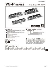
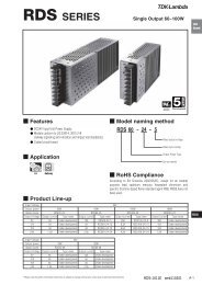
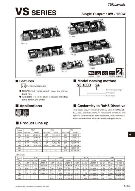
<strong>VS</strong> <strong>SERIES</strong>Single Output 10W - 150W<strong>VS</strong>150B<strong>VS</strong>100B <strong>VS</strong>75B<strong>VS</strong>50B ■ FeaturesCE marking applicable● 100VAC input / single output / super low cost onboard type<strong>VS</strong>10C ● Applicable to a wide range of usages, includinggame devices and printers■ Applications■ Product Line up <strong>VS</strong>-COutputVoltage <strong>VS</strong>15C10W 15W 30WOutput Current Model Output Current Model Output Current Model3.3V 2.0A <strong>VS</strong>10C-3 3.0A <strong>VS</strong>15C-3 6.0A <strong>VS</strong>30C-35V 2.0A <strong>VS</strong>10C-5 3.0A <strong>VS</strong>15C-5 6.0A <strong>VS</strong>30C-5 12V 0.9A <strong>VS</strong>10C-12 1.3A <strong>VS</strong>15C-12 2.5A <strong>VS</strong>30C-1215V 0.7A <strong>VS</strong>10C-15 1.0A <strong>VS</strong>15C-15 2.0A <strong>VS</strong>30C-1524V 0.5A <strong>VS</strong>10C-24 0.7A <strong>VS</strong>15C-24 1.3A <strong>VS</strong>30C-2436V - - - - 0.9A <strong>VS</strong>30C-3648V - - - -0.7A <strong>VS</strong>30C-48<strong>VS</strong>30C■ Model naming method<strong>VS</strong> 100B − 242Nominal output voltageOutput powerSeries name■ Conformity to RoHS DirectiveThis means that, in conformity with EU Directive 2002/95/EC, lead, cadmium, mercury, hexavalent chromium, andspecific bromine-based flame retardants, PBB and PBDE,have not been used, except for exempted applications.<strong>VS</strong> <strong>VS</strong>-B(Peak)Output50W 75W 100W 150WVoltage Output Current Peak Current Model Output Current Peak Current Model Output Current Peak Current Model Output Current Peak Current Model3.3V 10.0A 12.0A <strong>VS</strong>50B-3 15.0A 18.0A <strong>VS</strong>75B-3 20.0A 24.0A <strong>VS</strong>100B-3 30.0A 36.0A <strong>VS</strong>150B-35V 10.0A 12.0A <strong>VS</strong>50B-5 15.0A 18.0A <strong>VS</strong>75B-5 20.0A 24.0A <strong>VS</strong>100B-5 30.0A 36.0A <strong>VS</strong>150B-512V 4.3A 5.16A <strong>VS</strong>50B-12 6.3A 7.56A <strong>VS</strong>75B-12 8.5A 10.2A <strong>VS</strong>100B-12 12.5A 15.0A <strong>VS</strong>150B-1215V 3.5A 4.2A <strong>VS</strong>50B-15 5.0A 6.0A <strong>VS</strong>75B-15 7.0A 8.4A <strong>VS</strong>100B-15 10.0A 12.0A <strong>VS</strong>150B-1524V 2.5A 3.0A <strong>VS</strong>50B-24 3.2A 3.84A <strong>VS</strong>75B-24 4.3A 5.16A <strong>VS</strong>100B-24 6.3A 7.56A <strong>VS</strong>150B-2436V - - - 2.1A 2.52A <strong>VS</strong>75B-36 3.0A 3.6A <strong>VS</strong>100B-36 4.2A 5.04A <strong>VS</strong>150B-3648V - - - 1.6A 1.92A <strong>VS</strong>75B-48 2.2A 2.64A <strong>VS</strong>100B-48 3.2A 3.84A <strong>VS</strong>150B-48・All specifications are subject to change without notice.A-305
<strong>VS</strong>10C<strong>VS</strong>10C<strong>VS</strong>10C SpecificationsITEMS/UNITS MODEL <strong>VS</strong>10C-3 <strong>VS</strong>10C-5 <strong>VS</strong>10C-12 <strong>VS</strong>10C-15 <strong>VS</strong>10C-24InputVoltage Range (*2) V AC85-132 or DC110-175Frequency (*2) Hz 47-440Efficiency (typ) (*1) % 62 71 75 78Current (typ) (*1) A 0.3Inrush Current (100VAC)(typ) A 25, Ta=25℃Nominal Voltage VDC 3.3 5 12 15 24Minimum Current A 0Maximum Current A 2.0 0.9 0.7 0.5Maximum Power W 6.6 10.0 10.8 10.5 12.0Maximum Line Regulation (*3)(*4) mV 20 48 60 96OutputMaximum Load Regulation (*3)(*5) mV 40 96 120 150Temperature Coefficient (*3)(*6) mV 50 120 150 240Maximum Ripple & Noise (*3) mVp-p 120 150 200Hold-up Time (typ) (*1) ms 20 at 10WVoltage Adjustable Range ±10%Over Current Protection (*7) >105%Over Voltage Protection (*8) >115%FunctionParallel Operation -Series OperationPossibleOperating Temperature (*9) ℃ -10 to +50: 100%, +60: 70%Storage Temperature ℃ -30 to 85Operating Humidity %RH 30 - 90Environment Storage Humidity %RH 10 - 95VibrationShockCoolingInput-Output:Withstand VoltageIsolationIsolation ResistanceSafety StandardsStandardsEMI10-55Hz Amplitude (sweep 1min) Less than 19.6m/s² X, Y, Z 1h eachLess than 196.1m/s²Convection cooling2kVAC (20mA), Input-FG: 2kVAC (20mA)Output-FG: 500VAC (100mA) 1minMore than 100MΩ at 25℃ and 70% RH Output-FG 500VDCApproved by UL60950-1, CSA C22.2 No.60950-1, EN60950-1, Built to meet DENAN.Built to meet VCCI-B & FCC class BWeight (typ) g 65MechanicalSize (W x H x D) mm 49 x 17 x 94<strong>VS</strong>(*1) At 100VAC and maximum output power, Ta=25℃.(*2) For cases where conformance to various safety specs (UL, CSA, EN) are required to be described as100-120VAC, 50/60Hz on name plate.(*3) Please refer to Fig A for measurement determination of line & load regulation and output ripple voltage.(Measure with JEITA RC-9131 probe.)(*4) From 85-132VAC, constant load.(*5) From min load - Full load (maximum power), constant input voltage.(*6) From -10~+50℃ constant input voltage and load.(*7) Current limiting with automatic recovery, Avoid to operate over load or dead short for 30 seconds.(*8) Over voltage clamping by zener diode.(*9) At standard mounting method, Fig B.●Recommended EMC FilterRESL-20R5WPlease refer to "<strong>TDK</strong>-<strong>Lambda</strong>EMC Filters" catalog.A-306・All specifications are subject to change without notice.
<strong>VS</strong>10COutline Drawing【<strong>VS</strong>10C】 CONNECTORS USED :PART DESCRIPTION PART NAME MANUFACTURER QTYPIN HEADER (INPUT SIDE CN1) B3(7.5)B-XH-A J.S.T 1PIN HEADER (OUTPUT SIDE CN2) B2B-XH-A J.S.T 1MATCHING HOUSINGS & PINS :* NOT INCLUDED WITH THE PRODUCTPART DESCRIPTION PART NAME MANUFACTURER QTYSOCKET HOUSING (CN1) XHP-7 J.S.T 1SOCKET HOUSING (CN2) XHP-2 J.S.T 1TERMINAL PINS (CN1,2)BXH-001T-P0.6ORSXH-001T-P0.6J.S.T 5HAND CRIMPING TOOL : YC-110R CN1,2 MANUFACTURER : J.S.T: YRS-110 CN1,2 MANUFACTURER : J.S.Tunit: mmNOTES:A: THE 4XΦ3.5 HOLES ARE CUSTOMER CHASSIS MOUNTINGHOLES, ALL MUST BE SCREWED IN ORDER TO CONFORM THEVIBRATION SPEC.B: MODEL NAME, NOMINAL OUTPUT VOLTAGE, MAXIMUM OUT-PUT CURRENT ARE SHOWN HERE IN ACCORDANCE WITH THESPECIFICATIONS.C: COUNTRY OF MANUFACTURE WILL BE SHOWN HERE.D: TO KEEP THE DISTANCE MORE THAN 2mm BETWEEN PC-BOARD EDGE AND CUSTOMER CHASSIS.PCB MATERIAL:GLASS COMPOSITE : CEM-3Output Derating(CONVECTION COOLING)(FORCED AIR COOLING) <strong>VS</strong> MOUNTING(A)(standard)MOUNTING(B) MOUNTING(C) MOUNTING(D) MOUNTING(E)・All specifications are subject to change without notice.A-307
<strong>VS</strong>15C<strong>VS</strong>15C<strong>VS</strong>15C SpecificationsITEMS/UNITSMODEL <strong>VS</strong>15C-3 <strong>VS</strong>15C-5 <strong>VS</strong>15C-12 <strong>VS</strong>15C-15 <strong>VS</strong>15C-24Voltage Range (*2) V AC85-132 or DC110-175Frequency (*2) Hz 47-440Input Efficiency (typ) (*1) % 62 72 75 78Current (typ) (*1) A 0.4Inrush Current (100VAC)(typ) A 30, Ta=25℃Nominal Voltage VDC 3.3 5 12 15 24Minimum Current A 0Maximum Current A 3.0 1.3 1.0 0.7Maximum Power W 9.9 15.0 15.6 15.0 16.8OutputMaximum Line Regulation (*3)(*4) mV 20 48 60 96Maximum Load Regulation (*3)(*5) mV 40 96 120 150Temperature Coefficient (*3)(*6) mV 50 120 150 240Maximum Ripple & Noise (*3) mVp-p 120 150 200Hold-up Time (typ) (*1) ms 20 at 15WVoltage Adjustable Range ±10%Over Current Protection (*7) >105%Over Voltage Protection (*8) >115%FunctionParallel Operation -Series OperationPossibleOperating Temperature (*9) ℃ -10 to +50: 100%, +60: 70%Storage Temperature ℃ -30 to 85Operating Humidity %RH 30 - 90Environment Storage Humidity %RH 10 - 95Vibration10-55Hz amplitude (sweep 1min) less than 19.6m/s² X, Y, Z 1h eachShockLess than 196.1m/s²CoolingConvection coolingWithstand VoltageIsolationInput-Output: 2kVAC (20mA), Input-FG: 2kVAC (20mA)Output-FG: 500VAC (100mA) 1minIsolation ResistanceMore than 100MΩ at 25℃ and 70% RH Output-FG 500VDCSafety StandardsBuilt to meet UL1950, CSA950, EN60950, DENTORIStandardsEMIBuilt to meet VCCI-II & FCC class BWeight (typ) g 80MechanicalSize (W x H x D) mm 50 x 17 x 115(*1) At 100VAC and maximum output power, Ta=25℃.<strong>VS</strong>(*2) For cases where conformance to various safety specs (UL, CSA, EN) are required to be described as100-120VAC, 50/60Hz on name plate.(*3) Please refer to Fig A for measurement determination of line & load regulation and outputripple voltage. (Measure with JEITA RC-9131 probe.)(*4) From 85-132VAC, constant load.(*5) From min load - full load (maximum power), constant input voltage.(*6) From -10 to +50℃ constant input voltage and load.(*7) Current limiting with automatic recovery. Avoid to operate over load or dead short for30 seconds.(*8) Over voltage clamping by zener diode.(*9) At standard mounting method, Fig B.●Recommended EMC FilterRSEL-2001WPlease refer to "<strong>TDK</strong>-<strong>Lambda</strong>EMC Filters" catalog.A-308・All specifications are subject to change without notice.
<strong>VS</strong> 15COutline Drawing【<strong>VS</strong>15C】 unit: mmCONNECTORS USED :PART DESCRIPTIONPART NAME MANUFACTURER QTYPIN HEADER (INPUT SIDE CN1) B3(7.5)B-XH-A J.S.T 1PIN HEADER (OUTPUT SIDE CN2) B4B-XH-A J.S.T 1MATCHING HOUSINGS & PINS :* NOT INCLUDED WITH THE PRODUCT.PART DESCRIPTIONPART NAME MANUFACTURER QTYSOCKET HOUSING (CN1) XHP-7 J.S.T 1SOCKET HOUSING (CN2) XHP-4 J.S.T 1TERMINAL PINS (CN1,2)BXH-001T-P0.6OR J.S.T 7SXH-001T-P0.6HAND CRIMPING TOOL : YC-110R CN1,2 MANUFACTURER : J.S.T: YRS-110 CN1,2 MANUFACTURER : J.S.TNOTES :A: THE 4XΦ3.5 HOLES ARE CUSTOMER CHASSIS MOUNTING HOLES, ALL MUST BESCREWED IN ORDER TO CONFORM THE VIBRATION SPEC.B: MODEL NAME, NOMINAL OUTPUT VOLTAGE, MAXIMUM OUTPUT CURRENT ARE SHOWNHERE IN ACCORDANCE WITH THE SPECIFICATIONS.C: COUNTRY OF MANUFACTURE WILL BE SHOWN HERE.D: TO KEEP THE DISTANCE MORE THAN 2mm BETWEEN PC-BOARD EDGE AND CUSTOMERCHASSIS.PCB MATERIALGASS COMPOSIE: CEM-3Output Derating(CONVECTION COOLING)OUTPUT DERATING CURVE (FORCED AIR COOLING)OUTPUT DERATING CURVE <strong>VS</strong> MOUNTING(A)(standard)MOUNTING(B) MOUNTING(C) MOUNTING(D) MOUNTING(E)・All specifications are subject to change without notice.A-309
<strong>VS</strong>30C<strong>VS</strong>30C<strong>VS</strong>30C SpecificationsITEMS/UNITSInputMODEL <strong>VS</strong>30C-3 <strong>VS</strong>30C-5 <strong>VS</strong>30C-12 <strong>VS</strong>30C-15 <strong>VS</strong>30C-24 <strong>VS</strong>30C-36 <strong>VS</strong>30C-48Voltage Range (*2) V AC85-132 or DC110-175Frequency (*2) Hz 47-440Efficiency (typ) (*1) % 69 75 80 81 82 80Current (typ) (*1) A 0.7Inrush Current (100VAC)(typ) A 25A, cold start Ta=25℃Nominal Voltage VDC 3.3 5 12 15 24 36 48Minimum Current A 0Maximum Current A 6.0 2.5 2.0 1.3 0.9 0.7Maximum Power W 19.8 30.0 31.2 32.4 33.6Maximum Line Regulation (*3)(*4) mV 20 48 60 96 144 192OutputMaximum Load Regulation (*3)(*5) mV 40 96 120 150 240 300Temperature Coefficient (*3)(*6) mV 50 120 150 240 360 480Maximum Ripple & Noise (*3) mVp-p 120 150 200 300 400Hold-up Time (typ) (*1) ms 20 at 30WVoltage Adjustable Range ±10%Over Current Protection (*7) >105%Over Voltage Protection (*8) >115%FunctionParallel Operation -Series OperationPossibleOperating Temperature (*9) ℃ -10 to +50: 100%, +60: 70%Storage Temperature ℃ -30 to 85Operating Humidity %RH 30 - 90Environment Storage Humidity %RH 10 - 95VibrationShockCoolingInput-Output:Withstand VoltageIsolationIsolation ResistanceSafety StandardsStandardsEMI10-55Hz amplitude (sweep 1min) less than 19.6m/s² X, Y, Z 1h eachLess than 196.1m/s²Convection cooling2kVAC (20mA), Input-FG: 2kVAC (20mA)Output-FG: 500VAC (100mA) 1minMore than 100MΩ at 25℃ and 70% RH Output-FG 500VDCApproved by UL60950-1, CSA C22.2 No.60950-1, EN60950-1. Built to meet DENAN.Built to meet VCCI-B & FCC class BWeight (typ) g 150MechanicalSize (W x H x D) mm 50 x 25 x 132.5<strong>VS</strong>(*1) At 100VAC and maximum output power, Ta=25℃.(*2) For cases where conformance to various safety specs (UL, CSA, EN) are required to be described as100-120VAC, 50/60Hz on name plate.●Recommended EMC Filter(*3) Please refer to Fig A for measurement determination of line & load regulation and output ripple voltage.(Measure with JEITA RC-9131 probe.)(*4) From 85-132VAC, constant load.(*5) From min load - full load (maximum power), constant input voltage.(*6) From -10 to +50℃ constant input voltage and load.(*7) Current limiting with automatic recovery. Avoid to operate over load or dead short for 30 seconds.(*8) Over voltage clamping by zener diode.RSEL-2001W(*9) At standard mounting method, Fig B. Please refer to "<strong>TDK</strong>-<strong>Lambda</strong>EMC Filters" catalog.A-310・All specifications are subject to change without notice.
<strong>VS</strong> 30COutline Drawing【<strong>VS</strong>30C】CONNECTORS USED:PART DESCRIPTION PART NAME MANUFACTURER QTYPIN HEADER (INPUT SIDE CN1) B3P-5-VH J.S.T 1PIN HEADER (OUTPUT SIDE CN2) B4P-VH J.S.T 1MATCHING HOUSINGS AND PINS:* NOT INCLUDED WITH THE PRODUCT.PART DESCRIPTION PART NAME MANUFACTURER QTYSOCKET HOUSING (CN1) VHR-5N J.S.T 1SOCKET HOUSING (CN2) VHR-4N J.S.T 1TERMINAL PINS (CN1,2) SVH-21T-P1.1 J.S.T 7unit: mmNOTESA: THE 4XΦ3.5 HOLES ARE CUSTOMER CHASSIS MOUNTING HOLES. ALL MUST BE SCREWED IN ORDER TOCONFORM THE VIBRATION SPEC.B: MODEL NAME, NOMINAL OUTPUT VOLTAGE, MAXIMUM OUTPUT CURRENT ARE SHOWN HERE IN ACCOR-DANCE WITH THE SPECIFICATIONS.C: COUNTRY OF MANUFACTURE WILL BE SHOWN HERE.D: TO KEEP THE DISTANCE MORE THAN 2mm BETWEEN PC-BOARD EDGE AND CUSTOMER CHASSIS.E: C-UL-US , TUV AND CE MARKS FOR 3.3V, 5V, 12V, 15V, 24V, 36V, 48V ONLY.PCB MATERIALGLASS COMPOSITE : CEM-3HAND CRIMPING TOOL : YC-160R CN1,2MANUFACTURER : J.S.TOutput Derating(CONVECTION COOLING)OUTPUT DERATING CURVE(FORCED AIR COOLING)OUTPUT DERATING CURVE <strong>VS</strong> MOUNTING(A)(standard)MOUNTING(B) MOUNTING(C) MOUNTING(D) MOUNTING(E)・All specifications are subject to change without notice.A-311
<strong>VS</strong>50B<strong>VS</strong>50B SpecificationsITEMS/UNITSMODEL <strong>VS</strong>50B-3 <strong>VS</strong>50B-5 <strong>VS</strong>50B-12 <strong>VS</strong>50B-15 <strong>VS</strong>50B-24Voltage Range (*3) V AC85-132 or DC110-175Frequency (*3) Hz 47-440Input Efficiency (typ) (*2) % 73 78 79 80Current (typ) (*2) A 1.0A 1.2 1.4AInrush Current (100VAC)(typ) A cold start Ta=25℃Nominal Voltage VDC 3.3 5.0 12.0 15.0 24.0Minimum Current A 0Average Current A 10.0 4.3 3.5 2.5Maximum Peak Current (*1) A 12.0 5.16 4.2 3.0Average Power W 33.0 50.0 51.6 52.5 60.0OutputMaximum Peak Power (*1) W 39.6 60.0 61.92 63.0 72.0Maximum Line Regulation (*4)(*5) mV 20 48 60 96Maximum Load Regulation (*4)(*6) mV 40 96 120 150Temperature Coefficient (*4)(*7) mV 50 120 150 240Maximum Ripple & Noise (*4) mVp-p 120 150 200Hold-up Time (typ) (*2) ms 17 at 50WVoltage Adjustable Range +/-10%Over Current Protection (*8) >125%Over Voltage Protection (*9) 115% - 135%FunctionParallel Operation -Series OperationPossibleOperating Temperature (*10) ℃ -10 to 50: 100%, 60: 70%40:100%50: 88%, 60: 62%Storage Temperature ℃ -30 to 85Operating Humidity %RH 30 - 90EnvironmentStorage Humidity %RH 10 - 95Vibration10-55Hz amplitude (sweep 1min) less than 19.6m/s² X,Y,Z 1h eachShockLess than 196.1m/s²CoolingConvection coolingWithstand VoltageIsolationInput-Output: 2kVAC (20mA), Input-FG: 2kVAC (20mA)Output-FG: 500VAC (100mA) 1min.Isolation ResistanceMore than 100MΩ at 25℃ and 70%RH Output-FG 500VDCSafety StandardsApproved by UL60950-1, CSA C22.2 No.60950-1, EN60950-1, Built to meet DENAN.StandardsEMIBuilt to meet VCCI-B & FCC class BWeight (typ) g 200MechanicalSize (W x H x D) mm 50 x 25 x 195(*1) Operating time at peak output is less than 10 sec. (Duty=0.35)<strong>VS</strong>(*2) At 100VAC and average output power, Ta=25℃.(*3) For cases where conformance to various safety specs (UL, CSA) are required to be describedas 100-120VAC, 50/60Hz on name plate.(*4) Please refer to Fig A for measurement determination of line & load regulationand output ripple voltage.(*5) From 85-132VAC, constant load.(*6) From min load - full load (average power), constant input voltage.(*7) From -10~+50℃ constant input voltage and load.(*8) Current limiting with automatic recovery. Avoid to operate over load or dead shortfor 30 seconds.(*9) OVP circuit will shutdown output, manual reset.(*10) At standard mounting method, Fig B.●Recommended EMC FilterRSEL-2002WPlease refer to "<strong>TDK</strong>-<strong>Lambda</strong>EMC Filters" catalog.A-312・All specifications are subject to change without notice.
<strong>VS</strong> 50BOutline Drawing【<strong>VS</strong>50B】 CONNECTORS USED:PART DESCRIPTION PART NAME MANUFACTURER QTYPIN HEADER (INPUT SIDE CN1) B3P-5-VH J.S.T 1PIN HEADER (OUTPUT SIDE CN2) B4P-VH J.S.T 1ACCESSORIESSOCKET HOUSING (CN1) VHR-5N J.S.T 1SOCKET HOUSING (CN2) VHR-4N J.S.T 1TERMINAL PINS (CN1, 2) SVH-21T-P1.1 J.S.T 7HAND CRIMPING TOOL : YC-160R MANUFACTURER : J.S.Tunit: mmNOTESA: THE 4-3.5 HOLES ARE CUSTOMER CHASSIS MOUNTING HOLES, ALLMUST BE SCREWED IN ORDER TO CONFORM THE VIBRATION SPEC. B: MODEL NAME, NOMINAL OUTPUT VOLTAGE, AVERAGE OUTPUT CURRENT, PEAK OUTPUT CUERRENT ARE SHOWN HERE IN ACCORDANCE WITH THE SPECIFICATIONS.C: COUNTRY OF MANUFACTURE WILL BE SHOWN HERE.D: TO KEEP THE DISTANCE MORE THAN 2mm BETWEEN PC-BOARD EDGE ANDCUSTOMER CHASSIS.PCB MATERIALGLASS COMPOSITE : CEM-3Output Derating OUTPUT DERATING CURVE(3V, 5V, 12V, 15V) OUTPUT DERATING CURVE(24V) <strong>VS</strong>MOUNTING(A)(standard)MOUNTING(B) MOUNTING(C) MOUNTING(D) MOUNTING(E)・All specifications are subject to change without notice.A-313
<strong>VS</strong>75B<strong>VS</strong>75B SpecificationsITEMS/UNITSInputMODEL <strong>VS</strong>75B-3 <strong>VS</strong>75B-5 <strong>VS</strong>75B-12 <strong>VS</strong>75B-15 <strong>VS</strong>75B-24 <strong>VS</strong>75B-36 <strong>VS</strong>75B-48Voltage Range (*3) V AC85-132 or DC110-175Frequency (*3) Hz 47-440Efficiency (Typ) (*2) % 72.0 79.0 80.0 81.0Current (Typ) (*2) A 1.6 2.0Inrush Current (100VAC)(Typ) A 30A, cold start Ta: 25℃Nominal Voltage VDC 3.3 5 12 15 24 36 48Minimum Current A 0Average Current A 15.0 6.3 5.0 3.2 2.1 1.6Maximum Peak Current (*1) A 18.0 7.56 6.0 3.84 2.52 1.92Average Power W 49.5 75.0 75.6 75.0 76.8 75.6 76.8Maximum Peak Power (*1) W 59.4 90.0 90.72 90 92.16 90.72 92.16OutputMaximum Line Regulation (*4)(*5) mV 20 48 60 96 144 192Maximum Load Regulation (*4)(*6) mV 40 96 120 150 240 300Temperature Coefficient (*4)(*7) mV 50 120 150 240 360 480Maximum Ripple & Noise (*4) mVp-p 120 150 200 300 400Hold-up Time (Typ) (*2) ms 17 at 75WVoltage Adjustable Range ±10%Over Current Protection (*8) >125%FunctionOver Voltage Protection (*9) 115% - 135%Operating Temperature (*10) ℃ -10 to 50 : 100%, 60 : 70%Storage Temperature ℃ -30 to 85Operating Humidity %RH 30 - 90Environment Storage Humidity %RH 10 - 95VibrationShockCoolingInput-Output:Withstand VoltageIsolationIsolation ResistanceSafety StandardsStandardsEMI10-55Hz (sweep 1 min) Less than 19.6m/s² X.Y,Z 1h eachLess than 196.1m/s²Convection cooled2kVAC (20mA), Input-FG: 2kVAC (20mA)Output-FG: 500VAC (100mA) 1 minMore than 100M ohm at 25℃ and 70%RH Output-FG.. 500VDCApproved by UL60950-1, CSA C22.2 No.60950-1, EN60950-1. Built to meet DENAN.Built to meet VCCI-B & FCC class BWeight g 350MechanicalSize (W x H x D) mm 50 x 32 x 222<strong>VS</strong>(*1) Operating time at peak output current is less than 10 sec with average output power. (Duty: 0.35)(*2) At 100VAC and average output power, Ta: 25℃(*3) For cases where conformance to various safety specs (UL, CSA)are required to be described as 100-120VAC, 50/60Hz on name plate.(*4) Please refer to Fig A for measurement determination of line & load regulation and output ripple voltage.(*5) From 85-132VAC, constant load.(*6) For min load - full load (average power), constant input voltage.(*7) From -10 to +50℃ constant input voltage and load.(*8) Current limiting with automatic recovery. Avoid to operate over load or dead short for 30 seconds.(*9) OVP circuit will shutdown output, manual reset.(*10) At standard mounting method, Fig B.●Recommended EMC FilterRSEL-2003WPlease refer to "<strong>TDK</strong>-<strong>Lambda</strong>65EMC Filters" catalog.4321654321A-314・All specifications are subject to change without notice.
<strong>VS</strong> 75BOutline Drawing【<strong>VS</strong>75B】 CONNECTORS USED:PART DESCRIPTION PART NAME MANUFACTURER QTYPIN HEADER (INPUT SIDE CN1) B3P-5-VH J.S.T 1PIN HEADER (OUTPUT SIDE CN2) B6P-VH J.S.T 1ACCESSORIES:SOCKET HOUSING (CN1) VHR-5N J.S.T 1SOCKET HOUSING (CN2) VHR-6N J.S.T 1TERMINAL PINS (CN1,2) SVH-21T-P1.1 J.S.T 9HAND CRIMPING TOOL : YC-160R MANUFACTURER : J.S.TNOTESA : THE 5- 3.5 HOLES ARE CUSTOMER CHASSIS MOUNTING HOLES. ALL MUST BE SCREWEDIN ORDER TO CONFORM THE VIBRATION SPEC.B : MODEL NAME, NOMINAL OUTPUT VOLTAGE, AVERAGE OUTPUT CURRENT, PEAK OUT-PUT CURRENT ARE SHOWN HERE IN ACCORDANCE WITH THE SPECIFICATIONS.C : COUNTRY OF MANUFACTURE WILL BE SHOWN HERE. D : TO KEEP THE DISTANCE MORE THAN 2mm BETWEEN PC-BOARD EDGE AND CUSTOMER CHASSIS. PCB MATERIALGLASS COMPOSITE : CEM-3(unit : mm)Output Derating <strong>VS</strong>MOUNTING: A(standard)MOUNTING: B MOUNTING: C MOUNTING:D MOUNTING:E・All specifications are subject to change without notice.A-315
<strong>VS</strong>100B<strong>VS</strong>100B SpecificationsITEMS/UNITSInputMODEL <strong>VS</strong>100B-3 <strong>VS</strong>100B-5 <strong>VS</strong>100B-12 <strong>VS</strong>100B-15 <strong>VS</strong>100B-24 <strong>VS</strong>100B-36 <strong>VS</strong>100B-48Voltage Range (*3) V AC85-132 or DC110-175Frequency (*3) Hz 47-440Efficiency (typ) (*2) % 72 79 80 81Current (typ) (*2) A 1.8 2.2Inrush Current (100VAC)(typ) A 20Nominal Voltage VDC 3.3 5 12 15 24 36 48Minimum Current A 0Average Current A 20.0 8.5 7.0 4.3 3.0 2.2Maximum Peak Current (*1) A 24.0 10.2 8.4 5.16 3.6 2.64Average Power W 66.0 100.0 102.0 105.0 103.2 108.0 105.6Maximum Peak Power (*1) W 79.2 120.0 122.4 126.0 123.84 129.60 126.72OutputMaximum Line Regulation (*4)(*5) mV 20 48 60 96 144 192Maximum Load Regulation (*4)(*6) mV 40 96 120 150 240 300Temperature Coefficient (*4)(*7) mV 50 120 150 240 360 480Maximum Ripple & Noise (*4) mVp-p 120 150 200 300 400Hold-up Time (typ) (*2) ms 17 at 100WVoltage Adjustable Range +/-10%Over Current Protection (*8) >125%FunctionOver Voltage Protection (*9) 115% - 135%Operating Temperature (*10) ℃ -10 to 50: 100%, 60: 70%Storage Temperature ℃ -30 to +85Operating Humidity %RH 30 - 90Environment Storage Humidity %RH 10 - 95VibrationShockCoolingInput-Output:Withstand VoltageIsolationIsolation ResistanceSafety StandardsStandardsEMI10-55Hz (sweep 1min) Less than 19.6m/s² X, Y, Z 1h eachLess than 196.1m/s²Convection cooling2kVAC(20mA), Input-FG: 2kVAC(20mA)Output-FG: 500VAC(100mA) 1min.More than 100MΩ at 25℃ and 70%RH Output-FG 500VDCApproved by UL60950-1, CSA C22.2 No.60950-1, EN60950-1. Built to meet DENAN.Built to meet VCCI-B & FCC class BWeight (typ) g 420MechanicalSize (W x H x D) mm 62 x 32 x 222<strong>VS</strong>(*1) Operating time at peak output current is less than 10 sec.with average output power. (Duty=0.35)(*2) At 100VAC and average output power, Ta=25℃.(*3) For cases where conformance to various safety specs(UL, CSA) are required to be described as 100-120VAC, 50/60Hz on name plate.(*4) Please refer to Fig A for measurement determinationof line & load regulation and output ripple voltage.(*5) From 85-132VAC, constant load.(*6) From Min load - Full load (average power), constant input voltage.(*7) From -10 to +50℃ constant input voltage and load.(*8) Current limiting with automatic recovery. Avoid to operate over load or dead short for 30 seconds.(*9) OVP circuit will shutdown output, manual reset.(*10) At standard mounting method, Fig B.●Recommended EMC FilterRSEL-2006WPlease refer to "<strong>TDK</strong>-<strong>Lambda</strong>EMC Filters" catalog.8765432187654321A-316・All specifications are subject to change without notice.
<strong>VS</strong>100BOutline Drawing【<strong>VS</strong>100B】CONNECTORS USED:PART DESCRIPTION PART NAME MANUFACTURER QTY PIN HEADER (INPUT SIDE CN1) B3P-5-VH J.S.T 1 PIN HEADER (OUTPUT SIDE CN2) B8P-VH J.S.T 1ACCESSORIES:SOCKET HOUSING (CN1) VHR-5N J.S.T 1SOCKET HOUSING (CN2) VHR-8N J.S.T 1TERMINAL PINS (CN1,2) SVH-21T-P1.1 J.S.T 11HAND CRIMPING TOOL : YC-160R MANUFACTURER : J.S.TNOTESA: THE 5-3.5 HOLES ARE CUSTOMER CHASSIS MOUNTING HOLES, ALL MUSTBE SCREWED IN ORDER TO CONFORM THE VIBRATION SPEC.B: MODEL NAME, NOMINAL OUTPUT VOLTAGE, AVERAGE OUTPUT CURRENT,PEAK OUTPUT CUERRENT ARE SHOWN HERE IN ACCORDANCE WITH THESPECIFICATIONS.C: COUNTRY OF MANUFACTURE WILL BE SHOWN HERE.D: TO KEEP THE DISTANCE MORE THAN 2mm BETWEEN PC-BOARD EDGE ANDCUSTOMER CHASSIS.PCB MATERIALGLASS COMPOSITE : CEM-3unit: mmDerating Curve <strong>VS</strong>MOUNTING(A)standardMOUNTING(B) MOUNTING(C) MOUNTING(D) MOUNTING(E)・All specifications are subject to change without notice.A-317
<strong>VS</strong>150B<strong>VS</strong>150B SpecificationsITEMS/UNITS InputMODEL <strong>VS</strong>150B-3 <strong>VS</strong>150B-5 <strong>VS</strong>150B-12 <strong>VS</strong>150B-15 <strong>VS</strong>150B-18 <strong>VS</strong>150B-24 <strong>VS</strong>150B-36 <strong>VS</strong>150B-48Voltage Range (*3) V AC85-132 or DC110-175Frequency (*3) Hz 47-440Efficiency (typ) (*2) % 72 78.0 80 81Current (typ) (*2) A 2.5 3.2Inrush Current (100VAC)(typ) A 20Nominal Voltage V 3.3 5 12 15 18 24 36 48Minimum Current A 0Average Current A 30.0 12.5 10.0 8.5 6.3 4.2 3.2Maximum Peak Current (*1) A 36.0 15.0 12.0 10.2 7.56 5.04 3.84Average Power W 99.0 150.0 153.0 151.2 153.6Maximum Peak Power (*1) W 118.8 180.0 184.0 181.44 184.32OutputMaximum Line Regulation (*4)(*5) mV 20 48 60 72 96 144 192Maximum Load Regulation (*4)(*6) mV 40 96 120 140 150 240 300Temperature Coefficient (*4)(*7) mV 50 120 150 240 360 480Maximum Ripple & Noise (*4) mVp-p 120 150 200 300 400Hold-up Time (typ) (*2) ms 17 at 150WVoltage Adjustable Range +/-10%Over Current Protection (*8) >125%FunctionOver Voltage Protection (*9) 115% - 135%Operating Temperature (*10) ℃Convection: -10 to 25: 100%, 35: 90%, 50: 80%, 60: 60%Forced Air: -10 to 50: 100%, 60: 70%Storage Temperature ℃ -30 to +85Operating Humidity %RH 30 - 90EnvironmentStorage Humidity %RH 10 - 95VibrationShockCoolingInput-Output:Withstand VoltageIsolationIsolation ResistanceSafety StandardsStandardsEMI10 - 55Hz (sweep 1min) Less than 19.6m/s² X, Y, Z 1h eachLess than 196.1m/s²Convection & forced air cooling (Despends on o/p loading)2kVAC (20mA), Input-FG: 2kVAC (20mA)Output-FG: 500VAC (100mA) for 1min.More than 100MΩ at 25℃ and 70%RH Output-FG 500VDCApproved by UL60950-1, CSA C22.2 No.60950-1, EN60950-1. Built to meet DENAN.Built to meet VCCI-B & FCC class BWeight (typ) g 550MechanicalSize (W x H x D) mm 75 x 36 x 222<strong>VS</strong>(*1) Operating time at peak output current is less than 10sec. with average output power. (Duty=0.35)(*2) At 100VAC and average output power, Ta=25℃.(*3) For cases where conformance to various safety specs(UL, CSA) are required to be described as 100-120VAC, 50/60Hz on name plate.(*4) Please refer to Fig A for measurement determinationof line & load regulation and output ripple voltage.(*5) From 85-132VAC, constant load.(*6) From Min load - Full load (average power), constant input voltage.(*7) From -10 to +50℃ constant input voltage and load.(*8) Current limiting with automatic recovery. Avoid to operate over load or dead short for 30 seconds.(*9) OVP circuit will shutdown output, manual reset.(*10) At standard mounting method, Fig B.●Recommended EMC FilterRSEL-2006W6Please refer to "<strong>TDK</strong>-<strong>Lambda</strong>EMC Filters" catalog.7 67 A-318・All specifications are subject to change without notice.
<strong>VS</strong> 150BOutline Drawing【<strong>VS</strong>150B】 CONNECTORS USED:PART DESCRIPTION PART NAME MANUFACTURER QTYPIN HEADER (INPUT SIDE CN1) B3P-5-VH J.S.T 1PIN HEADER (OUTPUT SIDE CN2) B6P-VH J.S.T 1PIN HEADER (OUTPUT SIDE CN2) B4P-VH J.S.T 1ACCESSORIES:SOCKET HOUSING (CN1) VHR-5N J.S.T 1SOCKET HOUSING (CN2) VHR-6N J.S.T 1SOCKET HOUSING (CN3) VHR-7N J.S.T 1TERMINAL PINS (CN1,2,3) SVH-21T-P1.1 J.S.T 16HAND CRIMPING TOOL : YC-160R MANUFACTURER : J.S.Tunit: mm NOTES A: THE 5-3.5 HOLES ARE CUSTOMER CHASSIS MOUNTING HOLES, ALL MUST BE SCREWED IN ORDER TO CONFORM THE VIBRATION SPEC.B: MODEL NAME, NOMINAL OUTPUT VOLTAGE, AVERAGE OUTPUT CUR- RENT, PEAK OUTPUT CUERRENT ARE SHOWN HERE IN ACCORDANCEWITH THE SPECIFICATIONS. C: COUNTRY OF MANUFACTURE WILL BE SHOWN HERE.D: TO KEEP THE DISTANCE MORE THAN 2mm BETWEEN PC-BOARD EDGE AND CUSTOMER CHASSIS.PCB MATERIALGLASS COMPOSITE : CEM-3Output Derating(CONVECTION COOLING)(FORCED AIR COOLING) <strong>VS</strong>MOUNTING(A)(standard)MOUNTING(B) MOUNTING(C) MOUNTING(D) MOUNTING(E)・All specifications are subject to change without notice.A-319
<strong>VS</strong> <strong>SERIES</strong>Block diagram【<strong>VS</strong>10C, <strong>VS</strong>15C】* Current mode: Automatic flyback mode* Oscillation frequency: 60-400kHz* Internal fuse value: <strong>VS</strong>10C: 1.5A, <strong>VS</strong>15C: 2A【<strong>VS</strong>30C】* Current mode: Automatic flyback mode* Oscillation frequency: 60-400kHz* Fuse rating: <strong>VS</strong>30C: 3A【<strong>VS</strong>50B, <strong>VS</strong>75B, <strong>VS</strong>100B, <strong>VS</strong>150B】<strong>VS</strong>* Current mode: Single-ended forward mode* Oscillation frequency: <strong>VS</strong>50B: 200kHz (fixed)<strong>VS</strong>75B/<strong>VS</strong>100B/<strong>VS</strong>150B: 180kHz (fixed)* Internal fuse value: <strong>VS</strong>50B: 4A<strong>VS</strong>75B/<strong>VS</strong>100B: 5A, <strong>VS</strong>150B: 6.3AA-320・All specifications are subject to change without notice.
<strong>VS</strong> <strong>SERIES</strong>Be sure to read this instruction manual thoroughly before usingthis product. Pay attention to all warnings and cautions beforeusing the unit. Incorrect usage could lead to an electric shock,damage to the unit or a fire hazard.WARNING● Do not touch the internal components, they may have highvoltage or high temperature.You may get electric shock or burned.● When the unit is operating, keep your hands and face awayfrom it, you may get injured by an accident.1 <strong>VS</strong>10CTerminal explanation<strong>VS</strong> series Instruction ManualBEFORE USING THE POWER SUPPLY UNITCAUTION1. Terminal Explanation● Do not operate overload or dead short condition for morethan 30 seconds which could result in damage or insulationfailure.● This power supply is PC board type unit. PCB stress suchas bending, twisting could cause damage. Therefore, pleasehandle with care.● Do not modify the product. DENSEI-LAMBDA cannot beheld responsible for the performance and safety if any modificationis made to the product.● Use this product in a condition within the specified operatingambient temperature.● If a fuse in the product becomes burned out, it also causesdamage to parts in the product. Be sure to request us to repairthe unit.Basic connections (1) Input terminal (pin 1 of CN1) L: Live line (fuse in line)(2) Input terminal (pin 4 of CN1) N: Neutral line(3) FG terminal (pin 7 of CN1) FG: Frame ground(4) Frame ground (FG) (Connected to pin 7 of CN1)Must be connected to electrically safe ground of apparatus or equipment by electrically conductive spacers.The mounting surface of the spacer should be within MAX 6mm.(The area for locating a filler piece. should be within φ6mm.)(5) + Output terminal (pin 2 of CN2)(6) - Output terminal (pin 1 of CN2)(7) V.ADJ: Output voltage adjusting trimmer2 <strong>VS</strong>15CTerminals Basic connections(1) Input terminal (pin 1 of CN1)L: Live line (fuse in line)(2) Input terminal (pin 4 of CN1) N: Neutral line(3) FG terminal (pin 7 of CN1) FG: Frame ground(4) Frame ground (FG) (Connected to pin 7 of CN1)Must be connected to electrically safe ground ofapparatus or equipment by electrically conductivespacers.The mounting surface of the spacer should be withinMAX 6mm.(5) + Output terminal (pins 3 and 4 of CN2)(6) - Output terminal (pins 1 and 2 of CN2)(7) V.ADJ: Output voltage adjusting trimmer<strong>VS</strong> * Output current of each terminal pin must be lessthan 3A. If output current of more than 3A is required,use multiple terminals simultaneously.・All specifications are subject to change without notice.A-321
<strong>VS</strong> <strong>SERIES</strong>3 <strong>VS</strong>30CTerminals (1) Input terminal (pin 1 of CN1)L: Live line (fuse in line)(2) Input terminal (pin 3 of CN1) N: Neutral line(3) FG terminal (pin 5 of CN1) FG: Frame ground(4) Frame ground (FG) (Connected to pin 5 of CN1)Must be connected to electrically safe ground ofapparatus or equipment by electrically conductivespacers.The mounting surface of the spacer should bewithin MAX 6mm.(5) - Output terminal (pins 1 and 2 of CN2)(6) + Output terminal (pins 3 and 4 of CN2)(7) V.ADJ: Output voltage adjusting trimmerBasic connections * Output current of each terminal pin must beless than 5A. If output current of more than3A is required, use multiple terminals simultaneously.4 <strong>VS</strong>50BTerminals<strong>VS</strong>(1) Input terminal (pin 1 of CN1) L: Live line (fuse in line)(2) Input terminal (pin 3 of CN1) N: Neutral line(3) FG terminal (pin 5 of CN1) FG: Frame ground(4) Frame ground (FG) (Connected to pin 5 of CN1)Must be connected to electrically safe ground of apparatus or equipment by electrically conductive spacers.The mounting surface of the spacer should be within MAX 6mm.(5) - Output terminal (pins 1 and 2 of CN2)(6) + Output terminal (pins 3 and 4 of CN2)(7) Output voltage adjusting trimmer (VR1) Basic connections* Output current of each terminal pin must be less than 5A.If output current of more than 3A is required, use multiple terminals simultaneously.A-322・All specifications are subject to change without notice.
<strong>VS</strong> <strong>SERIES</strong>5 <strong>VS</strong>75BTerminals(1) Input terminal (pin 1 of CN1) L: Live line (fuse in line)(2) Input terminal (pin 3 of CN1) N: Neutral line(3) FG terminal (pin 5 of CN1) FG: Frame ground(4) Frame ground (FG) (Connected to pin 5 of CN1)Must be connected to electrically safe ground of apparatus or equipment by electrically conductive spacers.The mounting surface of the spacer should be within MAX 6mm.(5) - Output terminal (pins 1 to 3 of CN2)(6) + Output terminal (pins 4 to 6 of Cn2)(7) Output voltage adjusting trimmer (VR1)Basic connections* Output current of each terminal pin must be less than 5A.If output current of more than 3A is required, use multiple terminals simultaneously.6 <strong>VS</strong>100BTerminals(1) Input terminal (pin 1 of CN1) L: Live line (fuse in line)(2) Input terminal (pin 3 of CN1) N: Neutral line(3) FG terminal (pin 5 of CN1) FG: Frame ground(4) Frame ground (FG) (Connected to pin 5 of CN1)Must be connected to electrically safe ground of apparatus or equipment by electrically conductive spacers.The mounting surface of the spacer should be within MAX 6mm.(5) - Output terminal (pins 1 to 4 of CN2)(6) + Output terminal (pins 5 to 8 of CN2)(7) Output voltage adjusting trimmer (VR1)<strong>VS</strong>Basic connections* Output current of each terminal pin must be less than 5A.If output current of more than 3A is required, use multiple terminals simultaneously.・All specifications are subject to change without notice.A-323
<strong>VS</strong> <strong>SERIES</strong>7 <strong>VS</strong>150BTerminals(1) Input terminal (pin 1 of CN1) L: Live line (fuse in line)(2) Input terminal (pin 3 of CN1) N: Neutral line(3) FG terminal (pin 5 of CN1) FG: Frame ground(4) Frame ground (FG) (Connected to pin 1 of CN1)Must be connected to electrically safe ground of apparatus or equipment by electrically conductive spacers.The mounting surface of the spacer should be within MAX 6mm.(5) - Output terminal (pins 1 to 7 of CN2)(6) + Output terminal (pins 1 to 6 of CN2)(7) Output voltage adjusting trimmer (VR1)Basic connections* Output current of each terminal pin must be less than 5A.If output current of more than 3A is required, use multiple terminals simultaneously.<strong>VS</strong>A-324・All specifications are subject to change without notice.
<strong>VS</strong> <strong>SERIES</strong>2. Explanation of functions and notes1 Input Voltage RangeThe input voltage range is single phase AC 85-132VAC(47-440Hz) or DC110-175VDC. Input voltage which is out ofspecification may cause unit damage.2 Output Voltage RangeThe output voltage is set to the nominal DC output voltagevalue in the factory when shipping. V.ADJ trimmer near outputconnector can adjust the output voltage within the range.To turn the trimmer clockwise, the output voltage will be increased.Output voltage range is within ±10% of the nominaloutput voltage. Note over voltage protection (OVP) functionmay trigger if the output voltage is increased excessively.3 Over Voltage Protection (OVP)<strong>VS</strong>10C-<strong>VS</strong>30C:Zener clamp method is provided. OVP function clamps over115% of nominal output voltage. It the over voltage is appliedand the output voltage goes down, the output will not recover.Request us to repair the unit (charged service).<strong>VS</strong>50B-<strong>VS</strong>150B:Output shutdown method, manual reset type is provided.OVP function operates within 115-135% of nominal outputvoltage. When OVP triggers, the output will be shut down. Theinput shall be removed for a few minutes, and then re-input forrecovery of the output. OVP setting shall be fixed and not tobe adjusted externally.4 Over Current Protection (OCP)Primary side power detection system automatic resume typeis employed.OCP function operates when the output current exceeds125% (<strong>VS</strong>10C-30C: 105%) of maximum output current ofspecification. The output will be automatically recovered whenthe overload condition is canceled. Do not operate overload ordead short conditions for more than 30 seconds, which couldresult in damage or insulation failure.* OCP in <strong>VS</strong>10C/<strong>VS</strong>15C/<strong>VS</strong>30C is:fold back type.Note that if nonlinear loading such as lamp load, motor load,and constant current load is connected, output may not begenerated when starting up (for example, latching may occurat the point A in the figure below).5 RippleThe standard specification for maximum ripple value is measuredaccording to measuerment circuit specified by JEITA-RC9131. When load lines are longer, ripple becomes larger. Inthis case, electrolytic capacitor, film capacitor, etc., might benecessary to use across the load terminal. The output ripplecannot be measured accurately if the probe ground lead ofoscilloscope is too long. 6 Inrush current (except <strong>VS</strong>10C/<strong>VS</strong>15C)The inrush current protection circuit is provided. <strong>VS</strong>30C-<strong>VS</strong>75B use power thermistor to protect the circuit from inrushcurrent. Suppressed current will vary depending on thetemperature or when restarting input soon after stopping it.<strong>VS</strong>100B/<strong>VS</strong>150B use thyristor method.Please be careful to select input switch and fuse.7 Peak output current (<strong>VS</strong>50B-<strong>VS</strong>150B)Output current accommodates peak load. Relation betweenaverage output current and peak output current must satisfyformulas below.Use the unit under the conditions where operating time atpeak output is less than 10 sec, the period is more than10ms, and the duty is less than 0.35 (τ≦10 seconds). 8 Isolation Test Isolation resistance between output and FG (chassis) shall bemore than 100MΩ at 500VDC. For safety operation, voltagesetting of DC isolation tester must be done before the test.Ensure that it is fully discharged after the test.<strong>VS</strong>・All specifications are subject to change without notice.A-325
<strong>VS</strong> <strong>SERIES</strong>9 Withstand VoltageThis series is designed to withstand 2kVAC between inputand output, 2kVAC between input and FG, and 500VAC betweenoutput and FG, each for 1 minute. When testing withstandvoltage, set current limit of withstand voltage test equipmentat 20mA (Output-FG: 100mA).The applied voltage must be gradually increased from zeroto testing value and then gradually decreased for shut down.When timer is used, the power supply may be damaged byhigh impulse voltage at timer switch on and off. Connect inputand output as follows. 3. Mounting MethodInsert the spacer (Max φ8mm) of height over 8mm to lift theunit. The vibration and shock spec. is the value taken whenthe unit is raised by 8mm spacers.<strong>VS</strong>10C :2 pcs (Φ3.5)<strong>VS</strong>15C/30C/50B : 4 pcs (Φ3.5)<strong>VS</strong>75B-<strong>VS</strong>150B : 5 pcs (Φ3.5)Please leave 2mm space from the surfaces and the sides ofPCB, especially from the solder surface, 6mm space is necessary.If the space is not enough, the specification of insulationand withstand will not be satisfied.FG should be connected to the earth terminal of the apparatus.If not, the conducted noise and output noise will increase.4. Wiring MethodThe output load line and input line shall be separated andtwisted to improve noise sensitivity.Noise can be eliminated by attaching a capacitor with smallcapacitance to the load terminals.Input: <strong>VS</strong>10C/<strong>VS</strong>15C :AWG#30-#22<strong>VS</strong>30C - <strong>VS</strong>150B :AWG#22-#18Output: <strong>VS</strong>10C/<strong>VS</strong>15C :AWG#30-#22<strong>VS</strong>30C - <strong>VS</strong>150B :AWG#22-#185. External Fuse Rating<strong>VS</strong>Refer to the following fuse rating when selecting the externalfuses that are to be used on input line. Therefore use slowblowfuse or time-lug fuse. Do not use fast-blow fuse. Fuserating is specified by inrush current value at line turn-on. Donot select the fuse according to input current (rms) values underthe actual load condition.Model Fuse Value<strong>VS</strong>10C 1.5A<strong>VS</strong>15C 2A<strong>VS</strong>30C 3A<strong>VS</strong>50C 4AModel Fuse Value<strong>VS</strong>75B 5A<strong>VS</strong>100B 5A<strong>VS</strong>150B 6.3A6. Before concluding that the unit is at fault…A-326● Check if the rated input voltage is connected.● Check if the wiring of input and output is correct.● Ensure the input and output connectors are firmly attached,and the connector pins are firmly crimped.● Check if the wire material is not too thin.● Check if the output voltage control (V.ADJ) is properlyadjusted.● Ensure that a large capacitor is not connected on theoutput side.Capacitance by Output VoltageModel 3V 5V 12V 15V 24V 36V 48V<strong>VS</strong>10C 5,000µF −<strong>VS</strong>15C 5,000µF −<strong>VS</strong>30C 5,000µF 10,000µF<strong>VS</strong>50B 10,000µF −<strong>VS</strong>75B 5,000µF 30,000µF<strong>VS</strong>100B 5,000µF 30,000µF<strong>VS</strong>150B 5,000µF 30,000µF・All specifications are subject to change without notice.