HWS Series - TDK-Lambda
HWS Series - TDK-Lambda
HWS Series - TDK-Lambda
- No tags were found...

You also want an ePaper? Increase the reach of your titles
YUMPU automatically turns print PDFs into web optimized ePapers that Google loves.
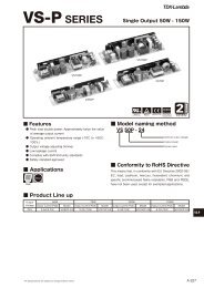
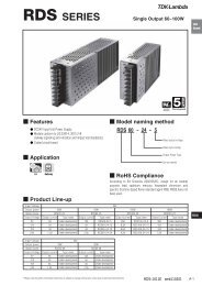
<strong>HWS</strong><strong>Series</strong>WIDE SELECTION OF LINE UP RANGE FROMGENERAL INDUSTRIAL, MEDICAL, HEAVY DUTYTO POWER SUPPLY WITH PEAK OUTPUT<strong>HWS</strong> <strong>Series</strong> put together the concept of"Environment-friendly", "User-friendly", and"Safety" as its foundation to offer wide rangeof product.Environmental-friendly Green power line Complies with RoHS Directive Energy Saving<strong>HWS</strong>User-friendly Miniature package Unified style Extensive product line High reliability design Safety-oriented design Safe to operate<strong>HWS</strong> <strong>Series</strong> Line Up<strong>HWS</strong>General industrial<strong>HWS</strong>/MEMedical standard (IEC60601) compliance<strong>HWS</strong>/HDSuitable for harsh environment/Heavy duty equipment<strong>HWS</strong>-PPeak power load■ <strong>HWS</strong> <strong>Series</strong> Model Name<strong>HWS</strong>-Option codeOutput voltageOutput power● Output powerIn addition to 11 models for 15W 1800W, there are 2 modelsfor peak power models which bring the total of 13 models.● Output voltageWide variety of line up from 3.3V to 48V. 60V is also available for 1000W and above models.● Option codeCodeMEHDARADINPVFGContentsEN/UL60601 Approved, low leakage current for medical applicationDouble-sided coating and -40start up, suitable for harsh environmentCover for additional safety operationRemote ON/OFF by external voltageDIN Reel typeExternal voltage adjustmentLow leakage current typeNot all models are available for above option and longer delivery might be needed for option models. Please contact our sales for more information
<strong>HWS</strong><strong>Series</strong>AC/DC Switching Power Supply<strong>HWS</strong>Line upP7Environment-friendlyComplies to RoHS DirectivesEnergy saving Reducing power loss during operation through high efficientdesign. Fan will stop during output "OFF" initiated by remote ON/OFF.PreviousmodelSaves19W<strong>HWS</strong>150WEfficiency (%)9085<strong>HWS</strong>150807570Previous model of 150W6560 3.3 5 12 15Output voltage24 48User-friendlyExhaust type forced air cooling using built-in fansinstalled at the rear of the unit (300W - 1800W )No space is required at theside between power supplieswhen multiple units are used.Built-in automated speedcontrol fan contribute to lowacoustic noise during normaltemperature operation.Miniature PackageBy increasing efficiencyand optimization of componetsand circuit design, weachieved over 50% miniaturization.Miniaturization of over 50%150W42±1Previousmodel1500W126.5±1PreviousmodelUnified styleUnified style of 82mm height make it moreconvenient in design when multiple unitsare used. All models can be embedded in19-inch 2U rack mountFit in 19-inch 2U rack mountH82mmSafetyReliability designSafety designLong Life105° long life elec. capacitors areused and design to operate for24 hours/365 days continouslyusing guranteed life time fromcomponent manufacturers.High efficiency designSynchronous rectification circuitis used in 3.3V/5V output to supportlower voltage higher current.These products achieved morethan 80% efficiencyWarranty: 5 yearsDesigned to meet worldwide safety regulation.It also meet the requirement for CEmarking, which is a safety standard in EuropeanUnion.UL508/CSA C22.2 No.14-M95UL60950-1/CSA C22.2No.60950-1EN50178Safety terminalPreviously, cover was required toensure safety in the terminal. Withsafety terminal, life areas are coveredby terminal block and directcontact with finger can be prevented (finger protection).With integral construction between screw and terminal, it willprevent the screw from dropping off into the unit (300W 1800W type are using input terminal)Live area, terminal screw are covered.Safety terminal does not require terminal coverTerminal are tightened with screwdriver.Screw cannot fall out or lossTerminal structure with integrated screwinserting round crimp terminalsafety is assured even without terminalcover<strong>HWS</strong>1000 - 1800 featured redmarking on the + side and blackmarking on the - of the outputterminal. This reduce the possibilityof incorrect connectionSafe operationWhile swicthing power supplyprovide stable DC power, thereare environmental conditionrequirement that unique to thedifferent fields in which equipmentis used. The momentary voltage drop (voltage sag) power supply fault thatmay occur due to certain natural disaster or lightning is a critical issuefor semiconductor factories and semiconductor manufacturing equipment.The supply voltage sag (voltage drop) and duration is stipulatedby the SEMIF47-0200, " Specification For Semiconductor ProcessingEquipment Voltage Sag Immunity" standard which is a US semicondutorequipment standard and can be met when 200VAC input is used.
<strong>HWS</strong><strong>Series</strong><strong>HWS</strong>/MEAC/DC Switching power supply formedical applicationEra where standard power supply used in medical applicationLine upP51Medical safety standard (EN60601/UL60601)complianceContribute to shortened the time needed in developingmedical equipment and reduce its cost7 models with 42 line upsMain applicationsMedical lasers,X-Ray,Microwave theraphyequipmentDiagnosis equipments,Analysis/testingdevicesLeakage current: max. 0.5mAEMC Immunity (All models)ItemsElectrostaticRadiated susceptibilityElectrical fast transient/burstSurgeConducted susceptibilityPower frequency magnetic fieldVoltage dips. Short interuptionStandardlEC61000-4-2lEC61000-4-3lEC61000-4-4lEC61000-4-5lEC61000-4-6lEC61000-4-8lEC61000-4-11Compliance LevelLevel3(Level 2,3 for300W, 600W)Level 3Level 3Level 3,4Level 3Level 4CompliedNotesAerial discharge: 8kVContact discharge:6kV(4kV for 1500W)10V/m2kVCommon: 4.0kVDifferential mode: 2.0kV10V30A/mEmission (<strong>HWS</strong>30,50,100,150,300/ME) Emission (<strong>HWS</strong> 600,1500/ME)Test itemsStandardNotesTest itemsStandardNotesRadiated electric fieldEN55022/EN55011,FCC,VCCIClass B ComplianceRadiated electric fieldEN55022/EN55011,FCC,VCCIClass A ComplianceConducted emissionsEN55022/EN55011,FCC,VCCIClass B ComplianceConducted emissionsEN55022/EN55011,FCC,VCCIClass A ComplianceConducted harmonicsIEC61000-3-2ConformedConducted harmonicsIEC61000-3-2ConformedFlickerIEC61000-3-3ConformedFlickerIEC61000-3-3ConformedAttention:Please read the instruction manual carefully before using this product. On top of the following condition, please refer to to "<strong>HWS</strong> <strong>Series</strong>" standard instruction manual (p25-).Please confirm whether there is insulation materials used inside the equipment (whether there is patient direct contact or indirect contact with the equipment). All models areapproved for basic insulation, therefore additional insulation circuit may be needed in the equipment.<strong>HWS</strong>/HDAC/DC Standard switching power supplyfor rugged and heavy dutyHarsh environment applicationsLine upP31-40 Start upMain applicationsPCB coatingDesigned to meet MIL-STD-810F(shock and vibration)LED displayDeviceProcesscontrolFactorymachinery
<strong>HWS</strong><strong>Series</strong>AC/DC Switching power supplywith peak power capabilitySupport drive load with 3 times of peak powerLine upP69Up to 3 times of peak currentMain applicationsHigh power in compact sizeLow acoustic noise with automated speed control fanFactorymachineySemiconductortesting deviceTextilemachinery,Cash dispenserUp to 3 times peak current to give powerfulsupport to motor and printer head applicationHigh Reliability and User Friendly Power Supply forDrive Load ApplicationThe growth of motor and printer head applications, the center ofmultifunction and high speed machineries, have been increasedfrom year to year. <strong>HWS</strong>-P is superior to provide function to supportinstant current in typical drive load with up to 3 times peakcurrent in compact size.By taking into consideration on the demand of high reliability industrialequipment, elec. capacitor is expected to have 7 year oflife (Ta=40°. Also, 5 year warranty is provided.The design include OCP circuit with shut off function, OVP circuit,temperature sensor for automatic speed control fan as well asbuilt-in OTP circuit. All of these functions give a better safety andease to the users.Output VoltageModeAve. outputcurrent<strong>HWS</strong>300P<strong>HWS</strong>600PPeak currentAve. outputPeak current100V input 200V input current100V input 200V input24V 12.5A 21.0A 42.0A 25.0A 40.5A 83.0A36V 8.4A 14.0A 28.0A 16.7A 27.0A 55.5A48V 6.3A 10.5A 21.0A 12.5A 20.0A 41.5A
<strong>HWS</strong>Specifications<strong>HWS</strong>15 8<strong>HWS</strong>30 10<strong>HWS</strong>50 12<strong>HWS</strong>80 14<strong>HWS</strong>100 16<strong>HWS</strong>150 18<strong>HWS</strong>300 20<strong>HWS</strong>600 22<strong>HWS</strong>1000 24<strong>HWS</strong>1500 26<strong>HWS</strong>1800T 28<strong>HWS</strong>/HD 31ContentsSpecifications<strong>HWS</strong>30/HD 32<strong>HWS</strong>50/HD 34<strong>HWS</strong>100/HD 36<strong>HWS</strong>150/HD 38<strong>HWS</strong>300/HD 40<strong>HWS</strong>600/HD 42<strong>HWS</strong>1000/HD 44<strong>HWS</strong>1500/HD 46<strong>HWS</strong>1800T/HD 48<strong>HWS</strong>/ME 51Specifications<strong>HWS</strong>30/ME 52<strong>HWS</strong>50/ME 54<strong>HWS</strong>100/ME 56<strong>HWS</strong>150/ME 58<strong>HWS</strong>300/ME 60<strong>HWS</strong>600/ME 62<strong>HWS</strong>1000/ME 64<strong>HWS</strong>1500/ME 66<strong>HWS</strong>-P 69Specifications<strong>HWS</strong>300P 70<strong>HWS</strong>600P 72<strong>HWS</strong> <strong>Series</strong> All 74Block Diagram<strong>HWS</strong>15, 30, 50, 80, 100, 150 74<strong>HWS</strong>300, 600, 1000 75<strong>HWS</strong>1500, 1800T 76Sequence Time Chart<strong>HWS</strong>300, 600, 1000 77<strong>HWS</strong>1500, 1800T 78Instruction Manual<strong>HWS</strong>15, 30, 50, 80, 100, 150 79<strong>HWS</strong>300, 600 85<strong>HWS</strong>1000 93<strong>HWS</strong>1500 104<strong>HWS</strong>1800T 113<strong>HWS</strong>300P, 600P 1247
<strong>HWS</strong> 5 <strong>HWS</strong> <strong>HWS</strong> HD <strong>HWS</strong> ME <strong>HWS</strong>-PInstruction Manual
<strong>HWS</strong> 15<strong>HWS</strong>15 Specifications(Read instruction manual carefully, before using the power supply unit.)<strong>HWS</strong> <strong>HWS</strong> HD <strong>HWS</strong> ME <strong>HWS</strong>-PInstruction ManualITEMS/UNITSMODEL <strong>HWS</strong>15-3 <strong>HWS</strong>15-5 <strong>HWS</strong>15-12 <strong>HWS</strong>15-15 <strong>HWS</strong>15-24 <strong>HWS</strong>15-48Voltage Range (*2) V AC85 - 265 or DC120 - 370Frequency (*2) Hz 47 - 63InputEfficiency (100/200VAC)(typ) (*1) 68 / 71 77 / 79 80 / 81 82 / 83 80 / 80Current (100/200VAC)(typ) (*1) A 0.3 / 0.15 0.4 / 0.2Inrush Current (100/200VAC)(typ) (*3) A 14 / 28, Ta=25, cold startLeakage Current (*10) mA Less than 0.5. (0.2 (typ) at 100VAC / 0.4 (typ) at 230VAC)Nominal Voltage VDC 3.3 5 12 15 24 48Maximum Current A 3 1.3 1 0.65 0.33Maximum Power W 10 15 15.6 15 15.6 15.8Maximum Line Regulation (*5) mV 20 48 60 96 192OutputMaximum Load Regulation (*6) mV 40 96 120 192 384Temperature CoefficientLess than 0.02% / Maximum Ripple & Noise (00.68 >0.34Over Voltage Protection (*8) VDC 4.13 - 4.95 6.25 - 7.25 15.0 - 17.4 18.8 - 21.8 30.0 - 34.8 55.2 - 64.8Remote Sensing -Function Remote ON/OFF Control -Parallel Operation -<strong>Series</strong> OperationPossibleLine DIPBuilt to meet SEMI-F47 (200VAC Line only)Operating Temperature (*11) -10 to +70 (-10 to +50: 100%, +60: 60%, +70: 20%)Storage Temperature -30 to +85Operating Humidity RH 30 - 90 (No dewdrop)Storage Humidity RH 10 - 95 (No dewdrop)EnvironmentAt no operating, 10 - 55Hz (sweep for 1min)Vibration19.6m/s² constant, X, Y, Z 1hour each.Shock (In package)Less than 196.1m/s²CoolingConvection coolingInput - FG : 2kVAC (20mA), Input - Output : 3kVAC (20mA)Withstand VoltageIsolation Output - FG : 500VAC (100mA) for 1minIsolation ResistanceMore than 100M at 25 and 70%RH Output - FG : 500VDCSafety Standards (*12)Approved by UL60950-1, CSA C22.2 No.60950-1, EN60950-1, EN50178 UL508 (with cover models only),CSA C22.2 No.14-M95 (with cover models only) Built to meet UL508, DENANPFHCBuilt to meet IEC61000-3-2StandardsEMIBuilt to meet EN55011/EN55022-B, FCC-B, VCCI-BImmunityBuilt to meet IEC61000-4-2(Level 2,3), -3(Level 3), -4(Level 3),-5(Level 3,4), -6(Level 3), -8(Level 4), -11Weight (typ) g 180MechanicalSize (W x H x D) mm 26.5 x 82 x 80 (Refer to outline drawing)(*1) At 100/200VAC, Ta=25 and maximum output power.(*2) For cases where conformance to various safety specs (UL, CSA, EN) are required, to be described as 100 - 240VAC (50/60Hz).(*3) Not applicable for the in-rush current to noise filter for less than 0.2ms.(*4) Measure with JEITA RC-9131A probe, bandwidth of scope :100MHz.For start up at low ambient temperature and low input voltage, output ripple noise might not meet specification.However, there is no overshoot at start up and output ripple noise specification can be met after one second.(*5) 85 - 265VAC, constant load.(*6) No load-Full load, constant input voltage.(*7) Foldback current limit with automatic recovery. Not operate at over load or dead shortcondition for more than 30 seconds.(*8) OVP circuit will shutdown output, manual reset (Re power on).(*9) At 100/200VAC, Ta=25, nominal output voltage and maximum output current.(*10) Measured by the each measuring method of UL, CSA, EN and DENAN (at 60Hz).(*11) Ratings - Derating at standard mounting.- Load (%) is percent of maximum output power or maximum output current, whichever is greater.- As for other mountings, refer to derating curve.(*12) As for DENAN, built to meet at 100VAC.
<strong>HWS</strong> 15Outline Drawing Output Derating<strong>HWS</strong> <strong>HWS</strong> HD <strong>HWS</strong> ME <strong>HWS</strong>-P Instruction Manual
<strong>HWS</strong> 30<strong>HWS</strong>30 Specifications(Read instruction manual carefully, before using the power supply unit.)<strong>HWS</strong> <strong>HWS</strong> HD <strong>HWS</strong> ME <strong>HWS</strong>-PInstruction ManualITEMS/UNITSMODEL <strong>HWS</strong>30-3 <strong>HWS</strong>30-5 <strong>HWS</strong>30-12 <strong>HWS</strong>30-15 <strong>HWS</strong>30-24 <strong>HWS</strong>30-48Voltage Range (*2) V AC85 - 265 or DC120 - 370Frequency (*2) Hz 47 - 63InputEfficiency (100/200VAC)(typ) (*1) 70 / 73 77 / 80 81 / 83 83 / 86 82 / 83Current (100/200VAC)(typ) (*1) A 0.6 / 0.3 0.8 / 0.4Inrush Current (100/200VAC)(typ) (*3) A 14 / 28, Ta=25, cold startLeakage Current (*10) mA Less than 0.5. (0.2 (typ) at 100VAC / 0.4 (typ) at 230VAC)Nominal Voltage VDC 3.3 5 12 15 24 48Maximum Current A 6 2.5 2 1.3 0.65Maximum Power W 20 30 31.2Maximum Line Regulation (*5) mV 20 48 60 96 192OutputMaximum Load Regulation (*6) mV 40 96 120 192 384Temperature CoefficientLess than 0.02% / Maximum Ripple & Noise (0≤Ta≤70) (*4) mVp-p 120 150 200Maximum Ripple & Noise (10≤Ta< 0) (*4) mVp-p 160 180 240Hold-up Time (typ) (*9) ms 20Voltage Adjustable Range VDC 2.97 - 3.96 4.0 - 6.0 9.6 - 14.4 12.0 - 18.0 19.2 - 28.8 38.4 - 52.8Over Current Protection (*7) A >6.3 >2.62 >2.1 >1.36 >0.68Over Voltage Protection (*8) VDC 4.13 - 4.95 6.25 - 7.25 15.0 - 17.4 18.8 - 21.8 30.0 - 34.8 55.2 - 64.8Remote Sensing -Function Remote ON/OFF Control -Parallel Operation -<strong>Series</strong> OperationPossibleLine DIPBuilt to meet SEMI-F47 (200VAC Line only)Operating Temperature (*11) -10 to +70 (-10 to +50: 100%, +60: 60%, +70: 20%)Storage Temperature -30 to +85Operating Humidity RH 30 - 90 (No dewdrop)Storage Humidity RH 10 - 95 (No dewdrop)EnvironmentAt no operating, 10 - 55Hz (sweep for 1min)Vibration19.6m/s² constant, X, Y, Z 1hour each.Shock (In package)Less than 196.1m/s²CoolingConvection coolingInput - FG : 2kVAC (20mA), Input - Output : 3kVAC (20mA)Withstand VoltageIsolation Output - FG : 500VAC (100mA) for 1minIsolation ResistanceMore than 100M at 25 and 70%RH Output - FG : 500VDCSafety Standards (*12)Approved by UL60950-1, CSA C22.2 No.60950-1, EN60950-1, EN50178 UL508 (with cover models only),CSA C22.2 No.14-M95 (with cover models only) Built to meet DENANPFHCBuilt to meet IEC61000-3-2StandardsEMIBuilt to meet EN55011/EN55022-B, FCC-B, VCCI-BImmunityBuilt to meet IEC61000-4-2(Level 2,3), -3(Level 3), -4(Level 3),-5(Level 3,4), -6(Level 3), -8(Level 4), -11Weight (typ) g 220MechanicalSize (W x H x D) mm 26.5 x 82 x 95 (Refer to outline drawing)(*1) At 100/200VAC, Ta=25 and maximum output power.(*2) For cases where conformance to various safety specs (UL, CSA, EN) are required, to be described as 100 - 240VAC (50/60Hz).(*3) Not applicable for the in-rush current to noise filter for less than 0.2ms.(*4) Measure with JEITA RC-9131A probe, bandwidth of scope :100MHz.For start up at low ambient temperature and low input voltage, output ripple noise might not meet specification.However, there is no overshoot at start up and output ripple noise specification can be met after one second.(*5) 85 - 265VAC, constant load.(*6) No load-Full load, constant input voltage.(*7) Foldback current limit with automatic recovery. Not operate at over load ordead short condition for more than 30 seconds.(*8) OVP circuit will shutdown output, manual reset (re power on).(*9) At 100/200VAC, Ta=25, nominal output voltage and maximum output current.(*10) Measured by the each measuring method of UL, CSA, EN and DENAN (at 60Hz).(*11) Ratings - Derating at standard mounting.- Load (%) is percent of maximum output power or maximum output current, whichever is greater.- As for other mountings, refer to derating curve.(*12) As for DENAN, built to meet at 100VAC.
<strong>HWS</strong> 30Outline DrawingOutput Derating<strong>HWS</strong> <strong>HWS</strong> HD <strong>HWS</strong> ME <strong>HWS</strong>-P Instruction Manual
<strong>HWS</strong> 50<strong>HWS</strong>50 Specifications(Read instruction manual carefully, before using the power supply unit.)<strong>HWS</strong> <strong>HWS</strong> HD <strong>HWS</strong> ME <strong>HWS</strong>-PInstruction ManualITEMS/UNITSMODEL <strong>HWS</strong>50-3 <strong>HWS</strong>50-5 <strong>HWS</strong>50-12 <strong>HWS</strong>50-15 <strong>HWS</strong>50-24 <strong>HWS</strong>50-48Voltage Range (*2) V AC85 - 265 or DC120 - 370Frequency (*2) Hz 47 - 63Power Factor (100/200VAC)(typ) (*1) 0.98 / 0.90 0.99 / 0.95Input Efficiency (100/200VAC)(typ) (*1) 76 / 78 82 / 84 81 / 83 82 / 84 83 / 85Current (100/200VAC)(typ) (*1) A 0.5 / 0.25 0.7 / 0.35Inrush Current (100/200VAC)(typ) (*3) A 14 / 28, Ta=25, cold startLeakage Current (*10) mA Less than 0.5. (0.2 (typ) at 100VAC / 0.4 (typ) at 230VAC)Nominal Voltage V 3.3 5 12 15 24 48Maximum Current A 10 4.3 3.5 2.2 1.1Maximum Power W 33 50 51.6 52.5 52.8Maximum Line Regulation (*5) mV 20 48 60 96 192OutputMaximum Load Regulation (*6) mV 40 96 120 192 384Temperature Coefficient Less than 0.02% /Maximum Ripple & Noise (0≤Ta≤70) (*4) mVp-p 120 150 200Maximum Ripple & Noise (10≤Ta< 0) (*4) mVp-p 160 180 240Hold-up Time (typ) (*9) ms 20Voltage Adjustable Range VDC 2.97 - 3.96 4.0 - 6.0 9.6 - 14.4 12.0 - 18.0 19.2 - 28.8 38.4 - 52.8Over Current Protection (*7) A >10.5 >4.51 >3.67 >2.31 >1.15Over Voltage Protection (*8) V 4.13 - 4.95 6.25 - 7.25 15.0 - 17.4 18.8 - 21.8 30.0 - 34.8 55.2 - 64.8Remote Sensing -Function Remote ON/OFF ControlPossible (/R Option)Parallel Operation -<strong>Series</strong> OperationPossibleLine DIPBuilt to meet SEMI-F47 (200VAC Line only)Operating Temperature (*11) -10 to +70 (-10 to +50: 100%, +60: 60%, +70: 20%)Storage Temperature -30 to +85Operating Humidity RH 30 - 90 (No dewdrop)Storage Humidity RH 10 - 95 (No dewdrop)EnvironmentAt no operating, 10 - 55Hz (sweep for 1min) 19.6m/s² constant,VibrationX, Y, Z 1hour each.Shock (In package)Less than 196.1m/s²CoolingConvection coolingInput - FG : 2kVAC (20mA), Input - Output : 3kVAC (20mA)Withstand VoltageIsolation Output - FG : 500VAC (100mA) for 1minIsolation ResistanceMore than 100M at 25 and 70%RH Output - FG : 500VDCSafety Standards (*12)Approved by UL60950-1, CSA C22.2 No.60950-1, EN60950-1, EN50178 UL508 (with cover models only),CSA C22.2 No.14-M95 (with cover models only) Built to meet DENANPFHCBuilt to meet IEC61000-3-2StandardsEMIBuilt to meet EN55011/EN55022-B, FCC-B, VCCI-BImmunityBuilt to meet IEC61000-4-2(Level 2,3), -3(Level 3), -4(Level 3), -5(Level 3,4), -6(Level 3), -8(Level 4), -11Weight (typ) g 280MechanicalSize (W x H x D) mm 26.5 x 82 x 120 (Refer to outline drawing)(*1) At 100/200VAC, Ta=25 and maximum output power.(*2) For cases where conformance to various safety specs (UL, CSA, EN) are required, to be described as 100 - 240VAC (50/60Hz).(*3) Not applicable for the in-rush current to noise filter for less than 0.2ms.(*4) Measure with JEITA RC-9131A probe, bandwidth of scope : 100MHz.(*5) 85 - 265VAC, constant load.(*6) No load-full load, constant input voltage.(*7) Constant current limit and hiccup with automatic recovery. Not operate at over loador dead short condition for more than 30 seconds.(*8) OVP circuit will shutdown output, manual reset (re power on).(*9) At 100/200VAC, nominal output voltage and maximum output current.(*10) Measured by the each measuring method of UL, CSA, EN and DENAN (at 60Hz).(*11) Ratings - Derating at standard mounting.- Load (%) is percent of maximum output power or maximum output current, whichever is greater.- As for other mountings, refer to derating curve.(*12) As for DENAN, built to meet at 100VAC.
<strong>HWS</strong> 50Outline DrawingOutput Derating<strong>HWS</strong> <strong>HWS</strong> HD <strong>HWS</strong> ME <strong>HWS</strong>-P Instruction Manual
<strong>HWS</strong> 80<strong>HWS</strong>80 Specifications(Read instruction manual carefully, before using the power supply unit.)<strong>HWS</strong> <strong>HWS</strong> HD <strong>HWS</strong> ME <strong>HWS</strong>-PInstruction ManualITEMS/UNITSMODEL <strong>HWS</strong>80-3 <strong>HWS</strong>80-5 <strong>HWS</strong>80-12 <strong>HWS</strong>80-15 <strong>HWS</strong>80-24 <strong>HWS</strong>80-48Voltage Range (*2) V AC85 - 265 or DC120 - 370Frequency (*2) Hz 47 - 63Power Factor (100/200VAC)(typ) (*1) 0.98 / 0.90 0.99 / 0.95Input Efficiency (100/200VAC)(typ) (*1) 77 / 79 82 / 85 83 / 85 84 / 86Current (100/200VAC)(typ) (*1) A 0.72 / 0.36 1.04 / 0.52Inrush Current (100/200VAC)(typ) (*3) A 14 / 28, Ta=25, cold startLeakage Current (*10) mA Less than 0.5. (0.2 (typ) at 100VAC / 0.4 (typ) at 230VAC)Nominal Voltage VDC 3.3 5 12 15 24 48Maximum Current A 16 6.7 5.4 3.4 1.7Maximum Power W 52.8 80 80.4 81 81.6Maximum Line Regulation (*5) mV 20 48 60 96 192OutputMaximum Load Regulation (*6) mV 40 96 120 192 384Temperature CoefficientLess than 0.02% / Maximum Ripple & Noise (0≤Ta≤70) (*4) mVp-p 120 150 200Maximum Ripple & Noise (10≤Ta< 0) (*4) mVp-p 160 180 240Hold-up Time (typ) (*9) ms 20msVoltage Adjustable Range VDC 2.97 - 3.96 4.0 - 6.0 9.6 - 14.4 12.0 - 18.0 19.2 - 28.8 38.4 - 52.8Over Current Protection (*7) A >16.8 >7.04 >5.67 >3.57 >1.79Over Voltage Protection (*8) VDC 4.13 - 4.95 6.25 - 7.25 15.0 - 17.4 18.8 - 21.8 30.0 - 34.8 55.2 - 64.8Remote SensingPossibleFunction Remote ON/OFF ControlPossible (/R Option)Parallel Operation -<strong>Series</strong> OperationPossibleLine DIPBuilt to meet SEMI-F47 (200VAC Line only)Operating Temperature (*11) -10 to +70 (-10 to +50: 100%, +60: 60%, +70: 20%)Storage Temperature -30 to +85Operating Humidity RH 30 - 90 (No dewdrop)Storage Humidity RH 10 - 95 (No dewdrop)EnvironmentAt no operating, 10 - 55Hz (sweep for 1min)Vibration19.6m/s² constant, X, Y, Z 1hour each.Shock (In package)Less than 196.1m/s²CoolingConvection coolingInput - FG : 2kVAC (20mA), Input - Output : 3kVAC (20mA)Withstand VoltageIsolation Output - FG : 500VAC (100mA) for 1minIsolation ResistanceMore than 100M at 25 and 70%RH Output - FG : 500VDCSafety Standards (*12)Approved by UL60950-1, CSA C22.2 No.60950-1, EN60950-1, EN50178 UL508 (with cover models only),CSA C22.2 No.14-M95 (with cover models only) Built to meet DENANPFHCBuilt to meet IEC61000-3-2StandardsEMIBuilt to meet EN55011/EN55022-B, FCC-B, VCCI-BImmunityBuilt to meet IEC61000-4-2(Level 2,3), -3(Level 3), -4(Level 3),-5(Level 3,4), -6(Level 3), -8(Level 4), -11Weight (typ) g 450MechanicalSize (W x H x D) mm 28 x 82 x 160 (Refer to outline drawing)(*1) At 100/200VAC, Ta=25 and maximum output power.(*2) For cases where conformance to various safety specs (UL, CSA, EN) are required, to be described as 100 - 240VAC (50/60Hz).(*3) Not applicable for the in-rush current to noise filter for less than 0.2ms.(*4) Measure with JEITA RC-9131A probe, bandwidth of scope : 100MHz.(*5) 85 - 265VAC , constant load.(*6) No load-full load, constant input voltage.(*7) Constant current limit and hiccup with automatic recovery. Not operate at over load ordead short condition for more than 30 seconds.(*8) OVP circuit will shutdown output, manual reset (re power on).(*9) At 100/200VAC, nominal output voltage and maximum output current.(*10) Measured by the each measuring method of UL, CSA, EN and DENAN (at 60Hz).(*11) Ratings - Derating at standard mounting.- Load (%) is percent of maximum output power or maximum output current, whichever is greater.- As for other mountings, refer to derating curve.(*12) As for DENAN, built to meet at 100VAC.
<strong>HWS</strong> 80Outline DrawingOutput Derating<strong>HWS</strong> <strong>HWS</strong> HD <strong>HWS</strong> ME <strong>HWS</strong>-P Instruction Manual
<strong>HWS</strong> 100<strong>HWS</strong>100 Specifications(Read instruction manual carefully, before using the power supply unit.)ITEMS/UNITSMODEL <strong>HWS</strong>100-3 <strong>HWS</strong>100-5 <strong>HWS</strong>100-12 <strong>HWS</strong>100-15 <strong>HWS</strong>100-24 <strong>HWS</strong>100-48<strong>HWS</strong> <strong>HWS</strong> HD <strong>HWS</strong> ME <strong>HWS</strong>-PInstruction ManualVoltage Range (*2) V AC85 - 265 or DC120 - 370Frequency (*2) Hz 47 - 63Power Factor (100/200VAC)(typ) (*1) 0.98 / 0.90 0.99 / 0.95Input Efficiency (100/200VAC)(typ) (*1) 78 / 81 83 / 86 84 / 87Current (100/200VAC)(typ) (*1) A 0.9 / 0.45 1.3 / 0.65Inrush Current (100/200VAC)(typ) (*3) A 14 / 28, Ta=25, cold startLeakage Current (*10) mA Less than 0.5. (0.2 (typ) at 100VAC / 0.4 (typ) at 230VAC)Nominal Voltage VDC 3.3 5 12 15 24 48Maximum Current A 20 8.5 7 4.5 2.1Maximum Power W 66 100 102 105 108 100.8Maximum Line Regulation (*5) mV 20 48 60 96 192OutputMaximum Load Regulation (*6) mV 40 96 120 192 384Temperature CoefficientLess than 0.02% / Maximum Ripple & Noise (0≤Ta≤70)(*4) mVp-p 120 150 200Maximum Ripple & Noise (10≤Ta< 0) (*4) mVp-p 160 180 240Hold-up Time (typ) (*9) ms 20Voltage Adjustable Range VDC 2.97 - 3.96 4.0 - 6.0 9.6 - 14.4 12.0 - 18.0 19.2 - 28.8 38.4 - 52.8Over Current Protection (*7) A >21.0 >8.92 >7.35 >4.72 >2.20Over Voltage Protection (*8) VDC 4.13 - 4.95 6.25 - 7.25 15.0 - 17.4 18.8 - 21.8 30.0 - 34.8 55.2 - 64.8Remote SensingPossibleFunction Remote ON/OFF ControlPossible (/R Option)Parallel Operation -<strong>Series</strong> OperationPossibleLine DIPBuilt to meet SEMI-F47 (200VAC Line only)Operating Temperature (*11) -10 to +70 (-10 to +50: 100%, +60: 60%, +70: 20%)Storage Temperature -30 to +85Operating Humidity RH 30 - 90 (No dewdrop)Storage Humidity RH 10 - 95 (No dewdrop)EnvironmentAt no operating, 10 - 55Hz (sweep for 1min) 19.6m/s² constant,VibrationX, Y, Z 1hour each.Shock (In package)Less than 196.1m/s²CoolingConvection coolingInput - FG : 2kVAC (20mA), Input - Output : 3kVAC (20mA)Withstand VoltageIsolation Output - FG : 500VAC (100mA) for 1minIsolation ResistanceMore than 100M at 25 and 70%RH Output - FG : 500VDCSafety Standards (*12)Approved by UL60950-1, CSA C22.2 No.60950-1, EN60950-1, EN50178 UL508 (with cover models only),CSA C22.2 No.14-M95 (with cover models only) Built to meet, DENANPFHCBuilt to meet IEC61000-3-2StandardsEMIBuilt to meet EN55011/EN55022-B, FCC-B, VCCI-BImmunityBuilt to meet IEC61000-4-2(Level 2,3), -3(Level 3), -4(Level 3),-5(Level 3,4), -6(Level 3), -8(Level 4), -11Weight (typ) g 450MechanicalSize (W x H x D) mm 28 x 82 x 160 (Refer to outline drawing)(*1) At 100/200VAC, Ta=25 and maximum output power.(*2) For cases where conformance to various safety specs (UL, CSA, EN) are required, to be described as 100 - 240VAC (50/60Hz).(*3) Not applicable for the in-rush current to noise filter for less than 0.2ms.(*4) Measure with JEITA RC-9131A probe, bandwidth of scope :100MHz.(*5) 85 - 265VAC, constant load.(*6) No load-Full load, constant input voltage.(*7) Constant current limit and hiccup with automatic recovery.Not operate at over load or dead short condition for more than 30 seconds.(*8) OVP circuit will shutdown output, manual reset (re power on).(*9) At 100/200VAC, nominal output voltage and maximum output current.(*10) Measured by the each measuring method of UL, CSA, EN and DENAN (at 60Hz).(*11) Ratings - Derating at standard mounting.- Load (%) is percent of maximum output power or maximum output current, whichever is greater.- As for other mountings, refer to derating curve(*12) As for DENAN, built to meet at 100VAC.
<strong>HWS</strong> 100Outline Drawing Output Derating<strong>HWS</strong> <strong>HWS</strong> HD <strong>HWS</strong> ME <strong>HWS</strong>-P Instruction Manual
<strong>HWS</strong> 150<strong>HWS</strong>150 Specifications(Read instruction manual carefully, before using the power supply unit.)<strong>HWS</strong> <strong>HWS</strong> HD <strong>HWS</strong> ME <strong>HWS</strong>-PInstruction ManualITEMS/UNITSMODEL <strong>HWS</strong>150-3 <strong>HWS</strong>150-5 <strong>HWS</strong>150-12 <strong>HWS</strong>150-15 <strong>HWS</strong>150-24 <strong>HWS</strong>150-48Voltage Range (*2) V AC85 - 265 or DC120 - 370Frequency (*2) Hz 47 - 63Power Factor (100/200VAC)(typ) (*1) 0.98 / 0.90 0.99 / 0.95Input Efficiency (100/200VAC)(typ) (*1) 78 / 81 83 / 86 85 / 88Current (100/200VAC)(typ) (*1) A 1.3 / 0.65 1.9 / 0.95Inrush Current (100/200VAC)(typ) (*3) A 14 / 28, Ta=25, cold startLeakage Current (*10) mA Less than 0.5. (0.2 (typ) at 100VAC / 0.4 (typ) at 230VAC)Nominal Voltage V 3.3 5 12 15 24 48Maximum Current A 30 13 10 6.5 3.3Maximum Power W 99 150 156 150 156 158.4Maximum Line Regulation (*5) mV 20 48 60 96 192OutputMaximum Load Regulation (*6) mV 40 96 120 192 384Temperature CoefficientLess than 0.02% / Maximum Ripple & Noise (0≤Ta≤70) (*4) mVp-p 120 150 200Maximum Ripple & Noise (10≤Ta< 0) (*4) mVp-p 160 180 240Hold-up Time (typ) (*9) ms 20Voltage Adjustable Range VDC 2.97 - 3.96 4.0 - 6.0 9.6 - 14.4 12.0 - 18.0 19.2 - 28.8 38.4 - 52.8Over Current Protection (*7) A >31.5 >13.6 >10.5 >6.82 >3.46Over Voltage Protection (*8) V 4.13 - 4.95 6.25 - 7.25 15.0 - 17.4 18.8 - 21.8 30.0 - 34.8 55.2 - 64.8Remote Sensing (*8) PossibleFunction Remote ON/OFF ControlPossible (/R Option)Parallel Operation -<strong>Series</strong> OperationPossibleLine DIPBuilt to meet SEMI-F47 (200VAC Line only)Operating Temperature (*11) -10 to +70 (-10 to +50: 100%, +60: 60%, +70: 20%)Storage Temperature -30 to +85Operating Humidity RH 30 - 90 (No dewdrop)Storage Humidity RH 10 - 95 (No dewdrop)EnvironmentAt no operating, 10 - 55Hz (sweep for 1min) 19.6m/s² constant,VibrationX, Y, Z 1hour each.Shock (In package)Less than 196.1m/s²CoolingConvection coolingInput - FG : 2kVAC (20mA), Input - Output : 3kVAC (20mA)Withstand VoltageIsolation Output - FG : 500VAC (100mA) for 1minIsolation ResistanceMore than 100M at 25 and 70%RH Output - FG : 500VDCSafety Standards (*12)Approved by UL60950-1, CSA C22.2 No.60950-1, EN60950-1, EN50178 UL508 (with cover models only),CSA C22.2 No.14-M95 (with cover models only)Built to meet DENANPFHCBuilt to meet IEC61000-3-2StandardsEMIBuilt to meet EN55011/EN55022-B, FCC-B, VCCI-BImmunityBuilt to meet IEC61000-4-2(Level 2,3), -3(Level 3), -4(Level 3),-5(Level 3,4), -6(Level 3), -8(Level 4), -11Weight (typ) g 500MechanicalSize (W x H x D) mm 37 x 82 x 160 (Refer to outline drawing)(*1) At 100/200VAC, Ta=25 and maximum output power.(*2) For cases where conformance to various safety specs (UL, CSA, EN) are required, to be described as 100 - 240VAC (50/60Hz).(*3) Not applicable for the in-rush current to noise filter for less than 0.2ms.(*4) Measure with JEITA RC-9131A probe, bandwidth of scope : 100MHz.(*5) 85 - 265VAC, constant load.(*6) No load-full load, constant input voltage.(*7) Constant current limit and hiccup with automatic recovery.Not operate at over load or dead short condition for more than 30 seconds.(*8) OVP circuit will shutdown output, manual reset (re power on).(*9) At 100/200VAC, nominal output voltage and maximum output current.(*10) Measured by the each measuring method of UL, CSA, EN and DENAN (at 60Hz).(*11) Ratings - Derating at standard mounting.- Load (%) is percent of maximum output power or maximum output current, whichever is greater.- As for other mountings, refer to derating curve.(*12) As for DENAN, built to meet at 100VAC.
<strong>HWS</strong> 150Outline Drawing Output Derating<strong>HWS</strong> <strong>HWS</strong> HD <strong>HWS</strong> ME <strong>HWS</strong>-P Instruction Manual
<strong>HWS</strong> 300<strong>HWS</strong>300 Specifications(Read instruction manual carefully, before using the power supply unit.)<strong>HWS</strong> <strong>HWS</strong> HD <strong>HWS</strong> ME <strong>HWS</strong>-PInstruction ManualITEMS/UNITSMODEL <strong>HWS</strong>300-3 <strong>HWS</strong>300-5 <strong>HWS</strong>300-12 <strong>HWS</strong>300-15 <strong>HWS</strong>300-24 <strong>HWS</strong>300-48Voltage Range (*2) V AC85 - 265 or DC120 - 330Frequency (*2) Hz 47 - 63Power Factor (100/200VAC)(typ) (*1) 0.99 / 0.95Input Efficiency (100/200VAC)(typ) (*1) 74 / 77 79 / 82 80 / 83 82 / 85Current (100/200VAC)(typ) (*1) A 2.7 / 1.4 3.8 / 1.9 4.1 / 2.1Inrush Current (100/200VAC)(typ) (*3) A 20 / 40Leakage Current (*10) mA Less than 0.75. (0.2 (typ) at 100VAC / 0.44 (typ) at 230VAC)Nominal Voltage VDC 3.3 5 12 15 24 48Maximum Current (*13) A 60 27 22 14 (16.5) 7Maximum Power W 198 300 324 330 336Maximum Line Regulation (*5) mV 20 48 60 96 192OutputMaximum Load Regulation (*6) mV 30 72 90 144 288Temperature CoefficientLess than 0.02% / Maximum Ripple & Noise (0≤Ta≤70) (*4) mVp-p 120 150 350Maximum Ripple & Noise (10≤Ta< 0) (*4) mVp-p 180 200 400Hold-up Time (typ) (*9) ms 20Voltage Adjustable Range VDC 2.64 - 3.96 4.0 - 6.0 9.6 - 14.4 12.0 - 18.0 19.2 - 28.8 38.4 - 52.8Over Current Protection (*7) A >63 > 28.4 >23.1 >16.7 >7.4Over Voltage Protection (*8) V 4.13 - 4.95 6.25 - 7.25 15.0 - 17.4 18.8 - 21.8 30.0 - 34.8 55.2 - 64.8Remote SensingPossibleRemote ON/OFF ControlPossibleFunctionParallel OperationPossible<strong>Series</strong> OperationPossibleMonitoring SignalPF (Open collector output)Line DIPDesigned to meet SEMI-F47 (200VAC Line only)Operating Temperature (*11) -10 to +70 (-10 to +50: 100%, +70: 50%)Storage Temperature -30 to +85Operating Humidity RH 10 - 90 (No dewdrop)Storage Humidity RH 10 - 95 (No dewdrop)EnvironmentAt no operating, 10 - 55Hz (sweep for 1min) 19.6m/s² constant,VibrationX, Y, Z 1hour each.Shock (In package)Less than 196.1m/s²CoolingForced air by blower fanWithstand VoltageIsolationIsolation ResistanceInput - FG : 2.5kVAC (20mA), Input - Output : 3kVAC (20mA)Output - FG: 500VAC (100mA), Output-CNT: 100VAC(100mA) for 1minMore than 100M Output - FG : 500VDCMore than 10M Output -CNT : 100VDC at 25 and 70%RHApproved by UL60950-1, UL508 (24V model only), CSA C22.2 No.60950-1,Safety Standards (*12)CSA C22.2 No.14-M95 (24V model only), EN60950-1, EN50178 Designed to meet DENANPFHCDesigned to meet IEC61000-3-2StandardsEMIDesigned to meet EN55011/EN55022-B, FCC-B, VCCI-BDesigned to meet IEC61000-4-2(Level 2,3), -3(Level 3), -4(Level3),Immunity-5(Level 3,4), -6(Level 3), -8(Level 4), -11Weight (typ) g 1000MechanicalSize (W x H x D) mm 61 x 82 x 165 (Refer to outline drawing)(*1) At 100/200VAC, Ta=25 and maximum output power.(*2) For cases where conformance to various safety specs (UL, CSA, EN) are required, to be described as 100-240VAC (50/60Hz).(*3) Not applicable for the inrush current to noise filter for less than 0.2ms.(*4) Measure with JEITA RC-9131A probe, bandwidth of scope :100MHz.(*5) 85 - 265VAC, constant load.(*6) No load-full load, constant input voltage.(*7) 3.3, 5V model: Constant current limit and hiccup with automatic recovery.12 - 48V model: Constant current limit with automatic recovery.Avoid to operate at over load or short circuit condition for more than 30 seconds.(*8) OVP circuit will shut the output down, manual reset (CNT reset or Re power on).(*9) At 100/200VAC, nominal output voltage and maximum output current.(*10) Measured by the each measuring method of UL, CSA, EN and DENAN (at 60Hz), Ta=25.(*11) Ratings - Derating at standard mounting. Refer to output derating curve.- Load (%) is percent of maximum output power or maximum output current, whichever is greater.(*12) As for DENAN, designed to meet at 100VAC.(*13) ( ): Peak output current at 200VAC. Operaing time at peak output is less than 10 sec, duty is less than 35%.
<strong>HWS</strong> 300Outline Drawing <strong>HWS</strong> <strong>HWS</strong> HD <strong>HWS</strong> ME <strong>HWS</strong>-POutput Derating Instruction Manual
<strong>HWS</strong> 600<strong>HWS</strong>600 Specifications(Read instruction manual carefully, before using the power supply unit.)<strong>HWS</strong> <strong>HWS</strong> HD <strong>HWS</strong> ME <strong>HWS</strong>-PInstruction ManualITEMS/UNITSMODEL <strong>HWS</strong>600-3 <strong>HWS</strong>600-5 <strong>HWS</strong>600-12 <strong>HWS</strong>600-15 <strong>HWS</strong>600-24 <strong>HWS</strong>600-48Voltage Range (*2) V AC85 - 265 or DC120 - 330Frequency (*2) Hz 47 - 63Power Factor (100/200VAC)(typ) (*1) 0.99 / 0.95Input Efficiency (100/200VAC)(typ) (*1) 75 / 78 80 / 83 81 / 84 82 / 85 83 / 86Current (100/200VAC)(typ) (*1) A 5.4 / 2.6 7.5 / 3.6 8.1 / 3.9Inrush Current (100/200VAC)(typ) (*3) A 20 / 40Leakage Current (*10) mA Less than 0.75. (0.2 (typ) at 100VAC / 0.44 (typ) at 230VAC)Nominal Voltage VDC 3.3 5 12 15 24 48Maximum Current (*13) A 120 53 43 27(31) 13Maximum Power W 396 600 636 645 648 624Maximum Line Regulation (*5) mV 20 48 60 96 192OutputMaximum Load Regulation (*6) mV 30 72 90 144 288Temperature CoefficientLess than 0.02 / Maximum Ripple & Noise (0≤Ta≤70) (*4) mVp-p 120 150 350Maximum Ripple & Noise (-10≤Ta≤ 0) (*4) mVp-p 180 200 400Hold-up Time (typ) (*9) ms 20msVoltage Adjustable Range VDC 2.64 - 3.96 4.0 - 6.0 9.6 - 14.4 12.0 - 18.0 19.2 - 28.8 38.4 - 52.8Over Current Protection (*7) A >126 >55.7 >45.2 >31.4 >13.7Over Voltage Protection (*8) VDC 4.13 - 4.95 6.25 - 7.25 15.0 - 17.4 18.8 - 21.8 30.0 - 34.8 55.2 - 64.8Remote SensingPossibleRemote ON/OFF ControlPossibleFunctionParallel OperationPossible<strong>Series</strong> OperationPossibleMonitoring SignalPF (Open collector output)Line DIPDesigned to meet SEMI-F47 (200VAC Line only)Operating Temperature (*11) -10 to +70 (-10 to +50: 100, +70: 50)Storage Temperature -30 to +85Operating Humidity RH 10 - 90 (No dewdrop)Storage Humidity RH 10 - 95 (No dewdrop)EnvironmentAt no operating, 10 - 55Hz (sweep for 1min) 19.6m/s² constant,VibrationX, Y, Z 1hour each.Shock (In package)Less than 196.1m/s²CoolingForced air by blower fanWithstand VoltageIsolationIsolation ResistanceInput - FG : 2.5kVAC (20mA), Input - Output : 3kVAC (20mA)Output - FG : 500VAC (100mA), Output - CNT : 100VAC (100mA) for 1minMore than 100M Output - FG : 500VDCMore than 10M Output - CNT: 100VDC at 25 and 70RHApproved by UL60950-1, UL508 (24V model only), CSA C22.2 No.60950-1,Safety Standards (*12)CSA C22.2 No.14-M95 (24V model only), EN60950-1, EN50178,Designed to meet DENANPFHCDesigned to meet IEC61000-3-2StandardsEMIDesigned to meet EN55011/EN55022-B, FCC-B, VCCI-BDesigned to meet IEC61000-4-2(Level 2,3), -3(Level 3),Immunity-4(Level 3), -5(Level 3,4), -6(Level 3), -8(Level 4), -11Weight (typ) g 1600MechanicalSize (W x H x D) mm 100 x 82 x 165 (Refer to outline drawing)(*1) At 100/200VAC, Ta=25 and maximum output power.(*2) For cases where conformance to various safety specs (UL, CSA, EN) are required, to be described as 100 - 240VAC(50/60Hz).(*3) Not applicable for the inrush current to noise filter for less than 0.2ms.Inrush current is 30A (typ) when PFHC start-up.(*4) Measure with JEITA RC-9131A probe, bandwidth of scope :100MHz.(*5) 85 - 265VAC, constant load.(*6) No load - full load, constant input voltage.(*7) 3V and 5V model: Constant current limit and hiccup with automatic recovery.12 - 48V model: Constant current limit with automatic recovery.Avoid to operate at over load or short circuit condition for more than 30 seconds.(*8) OVP circuit will shut the output down, manual reset (CNT reset or re-power on).(*9) At 100/200VAC, nominal output voltage and maximum output current.(*10) Measured by the each measuring method of UL, CSA, EN and DENAN (at 60Hz), Ta=25.(*11) Ratings - Derating at standard mounting. Refer to output derating curve.- Load (%) is percent of maximum output power or maximum output current, whichever is greater.(*12) As for DENAN, designed to meet at 100VAC.(*13) ( ): Peak output current at 200VAC. Operating time at peak output is less than 10 sec, duty is less than 35%.
<strong>HWS</strong> 600Outline Drawing <strong>HWS</strong> <strong>HWS</strong> HD <strong>HWS</strong> ME <strong>HWS</strong>-POutput Derating Instruction Manual
<strong>HWS</strong> 1000<strong>HWS</strong>1000 Specifications(Read instruction manual carefully, before using the power supply unit.)<strong>HWS</strong> <strong>HWS</strong> HD <strong>HWS</strong> ME <strong>HWS</strong>-PInstruction ManualITEMS/UNITSInputOutputMODELVoltage Range (*2) V AC85 - 265 or DC120 - 330Frequency (*2) Hz 47 - 63Power Factor (100/200VAC)(typ) (*1) 0.98 / 0.95Efficiency (100/200VAC)(typ) (*1) 71 / 73 76 / 78 79 / 81 80 / 82 82 / 85 83 / 85 85 / 87 85 / 88 86 / 88 85 / 88Current (100/200VAC)(typ) (*1) A 9.6 / 5.0 13.5 / 7.0Inrush Current (100/200VAC)(typ) (*3) A 20 / 40Leakage Current (100/240VAC) (*10) mA 1.2 maxNominal Voltage VDC 3.3 5 6 7.5 12 15 24 36 48 60Maximum Current A 200 167 134 88 70 46 30.7 23 18.4Maximum Peak Current (*13) A 160 100 80 58.5 39 29.2 23.4Maximum Power W 660 1000 1002 1005 1056 1050 1104Maximum Peak Power (*13) W 1200 1404Maximum Line Regulation (*5) mV 20 36 48 60 96 144 192 240Maximum Load Regulation (*6) mV 40 60 100 120 150 300 360Temperature CoefficientLess than 0.02%/MaximumRipple & Noise (*4)0 to +71C mVp-p 120 150 200 400-10 to 0C mVp-p 160 180 240 500 600Hold-up Time (typ) (*9) ms 20Voltage Adjustable Range VDC 2.64 - 3.96 4.0 - 6.0 4.8 - 7.2 6.0 - 9.0 9.6 - 14.4 12.0 - 18.0 19.2 - 28.8 28.8 - 43.2 38.4 - 52.8 48.0 - 66.0Over Current Protection (*7) A >210.0 >175.3 >168.0 >105.0 >84.0 >61.4 >40.9 >30.6 >24.5Over Voltage Protection (*8) VDC 4.12 - 4.62 6.25 - 7.0 7.5 - 8.4 9.37 - 10.5 15.0 - 17.4 18.7 - 21.8 30.0 - 34.8 45.0 - 49.7 55.2 - 60.0 69.0 - 75.0Remote SensingPossibleRemote ON/OFF ControlPossibleFunctionParallel OperationPossible<strong>Series</strong> OperationPossibleMonitoring SignalPF (Open collector output)Line DIPBuilt to meet SEMI-F47 (200VAC line only)Operating Temperature (*11) -10 to +71 , start up -20 to +71-10 to +40 100+50 83.9 100+71 50Storage Temperature -30 to +85EnvironmentOperating Humidity RH 10 - 90 (No Condensing)Storage Humidity RH 10 - 95 (No Condensing)VibrationAt no operating, 10 - 55Hz (sweep for 1min.) 19.6m/s² constant, X, Y, Z 1hour each.Shock (In package)Less than 196.1m/s²CoolingForced air by blower fanWithstand VoltageIsolationIsolation ResistanceInput - FG : 2kVAC (20mA), Input - Output : 3kVAC (20mA)Output-FG : 500VAC (300mA) (60V model 651VAC (390mA)), Output-CNT:100VAC (100mA) for 1min.More than 100M Output - FG : 500VDCMore than 10M Output - CNT 100VDC at 25 and 70%RHSafety Standards (*12) Approved by UL60950-1, CSA C22.2 No60950-1, EN60950-1,EN50178. Built to meet DENAN.PFHCBuilt to meet IEC61000-3-2Standards EMIBuilt to meet EN55011/EN55022-B, FCC-ClassB, VCCI-ClassB, CISPR-ClassB.ImmunityBuilt to meet IEC61000-4-2(Level 2,3), -3(Level 3), -4(Level 3),-5(Level 3,4), -6(Level 3), -8(Level 4), -11Weight (max) g 3200MechanicalSize (W x H x D) mm 126.5 x 82 x 240 (Refer to outline drawing)(*1) At Ta=25 and maximum output power.(*2) For cases where conformance to various safety specs (UL, CSA, EN) are required,input voltage range will be 100 - 240VAC (50/60Hz).(*3) First in-rush current. Not applicable to the first 0.2ms in-rush current flowing into the power supply noise filter.(*4) Measure with JEITA RC-9131A probe, bandwidth of scope :100MHz.At 100uF electric capacitor and 0.47uF film capacitor on the test fixture board.)(*5) 85 - 265VAC, constant load.(*6) No load-full load, constant input voltage.(*7) Constant current limit with automatic recovery. Over current condition for more than 5 seconds will cause theoutput to shutdown.Output current exceeding maximum rated output current for more then 10 seconds continuously will result tooutput shutdown.(*8) OVP circuit will shut down output, manual reset (power cycle) or ON/OFF CNT signal reset.(*9) At 100/200VAC, nominal output voltage and maximum output current.(*10) Measured by the each measuring method of UL, CSA, EN and DENAN (at 60Hz), Ta=25.(*11) Ratings - Derating at standard mounting. -Load (%) is percent of maximum output power or maximum output current, whichever is greater. -As for other mountings, refer to derating curve.(*12) As for DENAN, built to meet at 100VAC.(*13) Peak output current is less than 10 seconds, and duty 35% max.(200VAC Line only)
<strong>HWS</strong> 1000Outline Drawing Output Derating <strong>HWS</strong> <strong>HWS</strong> HD <strong>HWS</strong> ME <strong>HWS</strong>-P Instruction Manual
<strong>HWS</strong> 1500<strong>HWS</strong>1500 Specifications(Read instruction manual carefully, before using the power supply unit.)<strong>HWS</strong> <strong>HWS</strong> HD <strong>HWS</strong> ME <strong>HWS</strong>-PInstruction ManualITEMS/UNITSInputOutputFunctionMODEL <strong>HWS</strong>1500-3<strong>HWS</strong>1500-5<strong>HWS</strong>1500-6<strong>HWS</strong>1500-7<strong>HWS</strong>1500-12<strong>HWS</strong>1500-15<strong>HWS</strong>1500-24<strong>HWS</strong>1500-36<strong>HWS</strong>1500-48<strong>HWS</strong>1500-60Voltage Range (*2) V AC85 - 265 or DC120 - 330Frequency (*2) Hz 47 - 63Power Factor (100/230VAC)(typ) (*1) 0.98 / 0.94Efficiency (100/200VAC)(typ) (*1) 72 / 75 77 / 81 79 / 82 81 / 83 82 / 85 83 / 87 84 / 88 86 / 90Current (100/200VAC)(typ) (*1) A 15.0 / 8.0 19.5 / 10.0 19.0 / 10.0Inrush Current (100/200VAC)(typ) (*3) A 20 / 40Leakage Current (100/240VAC) (*10) mA 1.5 maxNominal Voltage VDC 3.3 5 6 7.5 12 15 24 36 48 60Maximum Current (100/200VAC) A 300 / 300 250 / 250 200 / 200 125 / 125 100 / 100 65 / 70 42 / 46.5 32 / 32 25.6 / 28Maximum Peak Current (*13) A 300 240 105 70 42Maximum Power (100/200VAC) W 990 / 990 1500 / 1500 1560 / 1680 1512 / 1674 1536 / 1536 1536 / 1680Maximum Peak Power (*13) W 1800 2520 2520Maximum Line Regulation (*5) mV 36 40 48 60 96 144 192 240Maximum Load Regulation (*6) mV 60 72 90 144 150 288 360Temperature CoefficientLess than 0.02%/+25 to +70 mVp-p 150 200 400Maximum0 mVp-p 200 150 200 400Ripple & Noise (*4)-10 mVp-p 220 200 240 400 600Hold-up Time (typ) (*9) ms 20 16 20Voltage Adjustable Range VDC 2.64 - 3.96 4.0 - 6.0 4.8 - 7.2 6.0 - 9.0 9.6 - 14.4 12.0 - 18.0 19.2 - 28.8 28.8 - 43.2 38.4 - 52.8 48.0 - 66.0Over Current Protection (*7) A >315.0 >262.5 >210.0 >131.2 >105.0 >68.2 >44.1 >33.6 >26.8Over Voltage Protection (*8) VDC 4.12 - 4.62 6.25 - 7.0 7.5 - 8.4 9.37 - 10.5 15.0 - 17.4 18.7 - 21.8 30.0 - 34.8 45.0 - 49.7 55.2 - 64.8 69.0 - 75.0Remote SensingPossibleRemote ON/OFF ControlPossibleParallel OperationPossible<strong>Series</strong> OperationPossibleMonitoring SignalPF (Open collector output)Line DIPBuilt to meet SEMI-F47 (200VAC Line only)Operating Temperature (*11) -10 to +70, start up -20 to +70at Input Voltage100VAC/200VAC-10 to +40°C W 990 1500 1560 / 1680 1512 / 1674 1536 1536 / 1680+50°C W 825 1250 1500 1560 / 1680 1512 / 1674 1536 1536 / 1680+60°C W 660 1000 1125 1170 / 1260 1134 / 1255 1152 1152 / 1260+70°C W 495 750 780 / 840 756 / 837 768 768 / 840Environment Storage Temperature -30 to +85Operating Humidity RH 10 - 90 (No Condensing)Storage Humidity RH 10 - 95 (No Condensing)VibrationAt no operating, 10 - 55Hz (sweep for 1min.) 19.6m/s² constant, X, Y, Z 1hour each.Shock (In package)Less than 196.1m/s²CoolingForced air by blower fanInput - FG : 2kVAC (20mA), Input - Output : 3kVAC (20mA), Output - CNT : 100VAC (100mA)Withstand VoltageIsolation Output - FG : 500VAC (300mA), (60V model 651VAC (390mA) ) for 1min.Isolation ResistanceMore than 100M Output - FG : 500VDC More than 10M Output - CNT 100VDC at 25 and 70%RHSafety Standards (*12) Approved by UL60950-1, CSA C22.2 No.60950-1, EN60950-1, EN50178. Built to meet DENAN.PFHCBuilt to meet IEC61000-3-2StandardsEMIBuilt to meet EN55011/EN55022-A, FCC-ClassA, VCCI-ClassA.Immunity Built to meet IEC61000-4-2(Level 2,3), -3(Level 3), -4(Level 3), -5(Level 3,4), -6(Level 3), -8(Level 4), -11Weight (typ) g 4000 3800MechanicalSize (W x H x D) mm 126.5 x 82 x 280 (Refer to outline drawing)(*1) At Ta=25 and maximum output power.(*2) For cases where conformance to various safety specs (UL, CSA, EN) are required, input voltage range will be 100 - 240VAC (50/60Hz).(*3) First in-rush current. Not applicable to the first 0.2ms in-rush current flowing into the power supply noise filter.(*4) Measure with JEITA RC-9131A probe, bandwidth of scope: 100MHz.(at 100uF electric capacitor and 0.47uF film capacitor on the test fixture board.)Ripple noise spec for ambient temperature between -10 to 25 is a linearity value with respect to the -10 degreesC and 25 degrees C specs.(*5) 85 - 265VAC, constant load.(*6) No load-Full load, constant input voltage.(*7) Constant current limit with automatic recovery. Over current condition for more than 5 seconds will cause the outputto shutdown. Output current exceeding maximum rated output current for more then 10 seconds continuouslywill result to output shutdown.(*8) OVP circuit will shut down output, manual reset (power cycle) or ON/OFF CNT signal reset.(*9) At 100/200VAC, nominal output voltage and maximum output current.(*10) Measured by the each measuring method of UL, CSA, EN and DENAN (at 60Hz), Ta=25.(*11) Ratings - Derating at standard mounting.- Load (%) is percent of maximum output power or maximum output current, whichever is greater.- As for other mountings, refer to derating curve.(*12) As for DENAN, built to meet at 100VAC.(*13) Peak output current is less than 10 seconds, and duty 35% max. (200VAC Line only)
<strong>HWS</strong> 1500Outline Drawing Output Derating <strong>HWS</strong> <strong>HWS</strong> HD <strong>HWS</strong> ME <strong>HWS</strong>-P Instruction Manual
<strong>HWS</strong> 1800T<strong>HWS</strong>1800T Specifications(Read instruction manual carefully, before using the power supply unit.)<strong>HWS</strong> <strong>HWS</strong> HD <strong>HWS</strong> ME <strong>HWS</strong>-PITEMS/UNITSInputOutputMODELVoltage Range (*2) V 3 AC170 - 265Frequency (*2) Hz 47 - 63Power Factor (200VAC)(typ) (*1) 0.94Efficiency (200VAC)(typ) (*1) 75 81 82 84 88 90Current (200VAC)(typ) (*1) A 4.5 6.0 7.0Inrush Current (200VAC)(typ) (*3) A 40Leakage Current (240VAC) (*10) mA 2.6 maxNominal Voltage VDC 3.3 5 6 7.5 12 15 24 36 48 60Maximum Current A 300 250 200 125 100 75 50 37.5 30Maximum Peak Current (*12) A - 300 240 150 120 105 70 52.5 42Maximum Power W 990 1500 1800Maximum Peak Power (*12) W - 1800 2520Maximum Line Regulation (*5) mV 36 40 48 60 96 144 192 240Maximum Load Regulation (*6) mV 60 72 90 144 216 288 360Temperature CoefficientLess than 0.02%/MaximumRipple & Noise+25 to +71 mVp-p 150 200 250 300 4000 mVp-p 200 250 300 400-10 mVp-p 220 250 300 400 600(*4)Hold-up Time (typ) (*9) ms 20 18Voltage Adjustable Range VDC 2.64-3.96 4.0-6.0 4.8-7.2 6.0-9.0 9.6-14.4 12.0-18.0 19.2-28.8 28.8-43.2 38.4-52.8 48.0-66.0Over Current Protection (*7) A >315.0 >303.0 >242.4 >151.5 >121.2 >106.0 >70.7 >53.0 >42.4Over Voltage Protection (*8) VDC 4.12-4.62 6.25-7.0 7.5-8.4 9.37-10.5 15.0-17.4 18.7-21.8 30.0-34.8 45.0-49.7 55.2-60.0 69.0-75.0Remote SensingPossibleRemote ON/OFF ControlPossibleFunction Output Voltage External Control PossibleParallel OperationPossible<strong>Series</strong> OperationPossibleMonitoring SignalPF (Open collector output)Line DIPBuilt to meet SEMI-F47Operating Temperature (*11) -10 to +71, Start up -20 to +71-10 to +40 W 990 1500 1800+50 W 825 1250 1500 1680+60 W 660 1000 1125 1300+71 W 495 750 900Environment Storage Temperature -30 to +85Operating Humidity RH 10 - 90 (No Condensing)Storage Humidity RH 10 - 95 (No Condensing)VibrationAt no operating, 10 - 55Hz (sweep for 1min.) 19.6m/s² constant, X, Y, Z 1hour each.Shock (In package)Less than 196.1m/s²CoolingForced air by blower fanWithstand VoltageIsolationIsolation ResistanceSafety StandardsEMIStandardsImmunityMechanicalInput - FG : 2kVAC (20mA), Input - Output : 3kVAC (20mA),Output-FG : 500VAC (300mA), (60V model 651VAC(390mA)), Output-CNT:100VAC (100mA) for 1minMore than 100M Output - FG : 500VDCMore than 10M Output - CNT 100VDC at 25 and 70%RHApproved by UL60950-1, CSA C22.2 No.60950-1, EN60950-1Built to meet EN55011/EN55022-A, FCC-ClassA, VCCI-ClassA.Built to meet IEC61000-4-2(Level 2,3), -3(Level 3), -4(Level 3),-5(Level 3,4), -6(Level 3), -8(Level 4), -11Weight (typ) g 4000 3800Size (W x H x D) mm 126.5 x 82 x 280 (Refer to outline drawing)Instruction Manual(*1) At Ta=25 and maximum output power.(*2) For cases where conformance to various safety specs (UL, CSA, EN) are required,input voltage range will be 200 - 240VAC (50/60Hz).(*3) First in-rush current. Not applicable to the first 0.2ms in-rush current flowing into the power supply noise filter.(*4) Measure with JEITA RC-9131A probe, bandwidth of scope: 100MHz.At 100uF electric capacitor and 0.47uF film capacitor on the test fixture board.)Ripple noise spec for ambient temperature between -10 to 25 is a linearity value with respect to the -10 degreesC and 25 degrees C specs.(*5) 170 - 265VAC, constant load.(*6) No load-full load, constant input voltage.(*7) Constant current limit with automatic recovery. Over current condition for more than 5 seconds will cause theoutput to shutdown.Output current exceeding maximum rated output current for more then 10 seconds continuously will result tooutput shutdown.(*8) OVP circuit will shut down output, manual reset (power cycle) or ON/OFF CNT signal reset.(*9) At 200VAC(50/60Hz), nominal output voltage and maximum output current.(*10) Measured by the each measuring method of UL, CSA and EN (at 60Hz), Ta=25.(*11) Ratings - Derating at standard mounting.- As for other mountings, refer to derating curve.(*12) Peak output current is less than 10 seconds, and duty 35% max.
<strong>HWS</strong> 1800TOutline Drawing FG L3 L2 L1 Output Derating <strong>HWS</strong> <strong>HWS</strong> HD <strong>HWS</strong> ME <strong>HWS</strong>-PInstruction Manual
<strong>HWS</strong>/HD UL60590-1/CSA C22.2 No.60950-1EN60950-1/EN50178 5 <strong>HWS</strong> <strong>HWS</strong> HD <strong>HWS</strong> ME <strong>HWS</strong>-PInstruction Manual
<strong>HWS</strong>30/HD<strong>HWS</strong>30/HD Specifications(Read instruction manual carefully, before using the power supply unit.)<strong>HWS</strong> <strong>HWS</strong> HD <strong>HWS</strong> ME <strong>HWS</strong>-PInstruction ManualITEMS/UNITSInputOutputMODEL <strong>HWS</strong>30-3/HD <strong>HWS</strong>30-5/HD <strong>HWS</strong>30-12/HD <strong>HWS</strong>30-15/HD <strong>HWS</strong>30-24/HD <strong>HWS</strong>30-48/HDVoltage Range (*2) V AC85 - 265 or DC120 - 370Frequency (*2) Hz 47 - 63Efficiency (100/200VAC)(typ) (*1) 70/73 77/80 81/83 83/86 82/83Current (100/200VAC)(typ) (*1) A 0.6/0.3 0.8/0.4Inrush Current (typ) (*3) A 14A at 100VAC, 28 at 200VAC, Ta=25C, Cold StartLeakage Current (*10) mA Less than 0.5m. (0.2(Typ) at 100VAC / 0.4mA(Typ) at 230VAC)Nominal Voltage VDC 3.3 5 12 15 24 48Maximum Current A 6 2.5 2 1.3 0.65Maximum Power W 20 30 31.2Maximum Line Regulation (*5) mV 20 48 60 96 192Maximum Load Regulation (*6) mV 40 96 120 192 384Temperature CoefficientLess than 0.02% / Maximum Ripple & Noise (0≤Ta≤71) (*4) mVp-p 120 150 200Maximum Ripple & Noise (-10≤Ta< 0) (*4) mVp-p 160 180 240Hold-up Time (typ) (*9) ms 20Voltage Adjustable Range VDC 2.97-3.96 4.0-6.0 9.6-14.4 12.0-18.0 19.2-28.8 38.4-52.8Over Current Protection (*7) A >6.3 >2.62 >2.1 >1.36 >0.68Over Voltage Protection (*8) VDC 4.13-4.95 6.25-7.25 15.0-17.4 18.8-21.8 30.0-34.8 55.2-64.8FunctionRemote Sensing -Parallel Operation -<strong>Series</strong> OperationPossibleLine DIPDesigned to meet SEMI-F47 (200VAC Line only)IsolationEnvironmentStandardsMechanicalOperating Temperature (*11) -10 to +71 (-10 to +50:100%,+60:60%,+71:20%)Guarantee Start up at -40 to -10Storage Temperature -40 to +85Operating Humidity RH 30 to 90 (No dewdrop)Storage Humidity RH 10 to 95 (No dewdrop)Vibration (*12)Shock (In package)CoolingWithstand VoltageIsolation ResistanceSafety Standards (*13)PFHCEMIImmunityAt no operating, 10 - 55Hz (Sweep for 1min) 19.6m/s² Constant, X,Y,Z 1hour each.Designed to meet MIL-STD-810F 514.5 Category 4, 10Less than 196.1m/s²Designed to meet MIL-STD-810F 516.5 Procedure I, VIConvection CoolingInput - FG : 2kVAC (20mA), Input - Output : 3kVAC (20mA) Output - FG : 500VAC (100mA) for 1minMore than 100M at 25C and 70%RH Output - FG : 500VDCApproved by UL60950-1, CSA60950-1, EN60950-1, EN50178Designed to meet UL508, DENANDesigned to meet IEC61000-3-2Designed to meet EN55011/EN55022-B, FCC-B, VCCI-BDesigned to meet IEC61000-4-2(Level 2,3), -3(Level 3), -4(Level 3),-5(Level 3,4), -6(Level 3), -8(Level 4), -11Weight (typ) g 220gSize (WHD) mm 26.5 x 82 x 95 ( Refer to Outline Drawing )(*1) At 100/200VAC, Ta=25°C and maximum output power.(*2) For cases where conformance to various safety specs (UL, CSA, EN) are required, to be described as 100 - 240VAC(50/60Hz).(*3) Not applicable for the in-rush current to Noise Filter for less than 0.2ms.(*4) Measure with JEITA RC-9131A probe, Bandwidth of scope :100MHz.For start up at low ambient temperature and low input voltage, output ripple noise might not meet specification.However, there is no overshoot at start up and output ripple noise specification can be met after one second.(*5) 85 - 265VAC , constant load.(*6) No load-Full load, constant input voltage.(*7) Foldback current limit with automatic recovery. Not operate at over load or dead short conditionfor more than 30seconds.(*8) OVP circuit will shutdown output, manual reset (Re power on).(*9) At 100/200VAC , Ta=25°C, nominal output voltage and maximum output current.(*10) Measured by the each measuring method of UL,CSA,EN and DENAN(at 60Hz).(*11) Ratings - Derating at standard mounting.- Load (%) is percent of maximum output power or maximum output current, whichever is greater.- As for other mountings, refer to derating curve.- For conditions of start up at -40C to -30C, refer to derating curve.- For conditions of start up at -30C to -10C, refer to derating curve.(*12) Category 4 exposure levels : Track transportation over U.S. highways, Composite two-wheeled trailer.(*13) As for DENAN, designed to meet at 100VAC.
<strong>HWS</strong>30/HDOutline Drawing Output Derating Start-up condition at low temperature <strong>HWS</strong> <strong>HWS</strong> HD <strong>HWS</strong> ME <strong>HWS</strong>-P Instruction Manual
<strong>HWS</strong>50/HD<strong>HWS</strong>50/HD Specifications(Read instruction manual carefully, before using the power supply unit.)<strong>HWS</strong> <strong>HWS</strong> HD <strong>HWS</strong> ME <strong>HWS</strong>-PInstruction ManualITEMS/UNITSMODEL <strong>HWS</strong>50-3/HD <strong>HWS</strong>50-5/HD <strong>HWS</strong>50-12/HD <strong>HWS</strong>50-15/HD <strong>HWS</strong>50-24/HD <strong>HWS</strong>50-48/HDVoltage Range (*3) V AC85 - 265 or DC120 - 370Frequency (*3) Hz 47 - 63Power Factor (100/200VAC)(typ) (*2) 0.98 / 0.90 0.99 / 0.95Input Efficiency (100/200VAC)(typ) (*2) 76 / 78 82 / 84 81 / 83 82 / 84 83 / 85Current (100/200VAC)(typ) (*2) A 0.5 / 0.25 0.7 / 0.35Inrush Current (100/200VAC)(typ) (*4) A 14 / 28 Ta=25, cold startLeakage Current (*11) mA Less than 0.5. (0.2 (typ) at 100VAC / 0.4 (typ) at 230VAC)Nominal Voltage VDC 3.3 5 12 15 24 48Minimum Current (*1) A 0.1 0.04 0.02 0.01Maximum Current A 10 4.3 3.5 2.2 1.1Maximum Power W 33 50 51.6 52.5 52.8Maximum Line Regulation (*6) mV 20 48 60 96 192Output Maximum Load Regulation (*7) mV 40 96 120 192 384Temperature CoefficientLess than 0.02% / Maximum Ripple & Noise (03.67 >2.31 >1.15Over Voltage Protection (*9) VDC 4.13 - 4.95 6.25 - 7.25 15.0 - 17.4 18.8 - 21.8 30.0 - 34.8 55.2 - 64.8Remote Sensing -FunctionParallel Operation -<strong>Series</strong> OperationPossibleLine DIPDesigned to meet SEMI-F47 (200VAC Line only)Operating Temperature (*12) -10 to +71 (-10 to +50: 100%, +60: 60%, +71: 20%)Guarantee start up at -40 to -10Storage Temperature -40 to +85Operating Humidity RH 30 - 90 (No dewdrop)Storage Humidity RH 10 - 95 (No dewdrop)EnvironmentVibration (*13)At no operating, 10 - 55Hz (sweep for 1min)19.6m/s² constant, X, Y, Z 1hour each.Designed to meet MIL-STD-810F 514.5 Category 4, 10Shock (In package)Less than 196.1m/s²Designed to meet MIL-STD-810F 516.5 Procedure I, VICoolingConvection coolingInput - FG : 2kVAC (20mA), Input - Output : 3kVAC (20mA)Withstand VoltageIsolation Output - FG : 500VAC (100mA) for 1minIsolation ResistanceMore than 100M at 25 and 70%RH Output - FG : 500VDCSafety Standards (*14)Approved by UL60950-1, CSA C22.2 No.60950-1, EN60950-1, EN50178Designed to meet UL508, DENANPFHCDesigned to meet IEC61000-3-2StandardsEMIDesigned to meet EN55011/EN55022-B, FCC-B, VCCI-BImmunityDesigned to meet IEC61000-4-2(Level 2,3), -3(Level 3), -4(Level 3),-5(Level 3,4), -6(Level 3), -8(Level 4), -11Weight (typ) g 280MechanicalSize (W x H x D) mm 26.5 x 82 x 120 (Refer to outline drawing)(*1) Output voltage might be unstable when start up at -40 to -10 and no load. In that case, apply minimum output current.(*2) At 100/200VAC, Ta=25 and maximum output power.(*3) For cases where conformance to various safety specs (UL, CSA, EN) are required, to be described as 100 - 240VAC(50/60Hz).(*4) Not applicable for the in-rush current to noise filter for less than 0.2ms.(*5) Measure with JEITA RC-9131A probe, bandwidth of scope :100MHz.(*6) 85 - 265VAC, constant load.(*7) No load-Full load, constant input voltage.(*8) Constant current limit and hiccup with automatic recovery. Not operate at over load ordead short condition for more than 30 seconds.(*9) OVP circuit will shutdown output, manual reset (re power on).(*10) At 100/200VAC, nominal output voltage and maximum output current.(*11) Measured by the each measuring method of UL, CSA, EN and DENAN (at 60Hz).(*12) Ratings - Derating at standard mounting.- Load (%) is percent of maximum output power or maximum output current, whichever is greater.- As for other mountings, refer to derating curve.- For conditions of start up at -40 to -10, refer to derating curve.(*13) Category 4 exposure levels : Track transportation over U.S. highways, composite two-wheeled trailer.(*14) As for DENAN, dsigned to meet at 100VAC.
<strong>HWS</strong>50/HDOutline Drawing =NOTES=*At Ta : -30 to -10C.*Output voltage : Nominal output voltage.*Input voltage : Not gradual start up.*Do not use the load that is constant current mode.*Avoid forced air cooling. It is assumed that inside of power supply is heatedby self-heating within 1 minutes.*No dewdrop.*Output voltage might be unstable at no load. In that case, apply minimumoutput current.*Pay attention to above items before using the unit. Incorrect usage couldlead to unstable output voltage. Output Derating Start-up condition at low temperature =NOTES=*At Ta : -40 to -10C.*Output voltage : Nominal output voltage.*Input voltage : Not operate at 85 - 90VAC, and not gradual start up.*Do not use the load that is constant current mode.*Avoid forced air cooling. It is assumed that inside of power supply is heatedby self-heating within 3 minutes.*No dewdrop.*Output voltage might be unstable at no load. In that case, apply minimumoutput current.*Pay attention to above items before using the unit. Incorrect usage couldlead to unstable output voltage.<strong>HWS</strong> <strong>HWS</strong> HD <strong>HWS</strong> ME <strong>HWS</strong>-PInstruction Manual
<strong>HWS</strong>100/HD<strong>HWS</strong>100/HD Specifications(Read instruction manual carefully, before using the power supply unit.)<strong>HWS</strong> <strong>HWS</strong> HD <strong>HWS</strong> ME <strong>HWS</strong>-PInstruction ManualITEMS/UNITSMODEL <strong>HWS</strong>100-3/HD <strong>HWS</strong>100-5/HD <strong>HWS</strong>100-12/HD <strong>HWS</strong>100-15/HD <strong>HWS</strong>100-24/HD <strong>HWS</strong>100-48/HDVoltage Range (*3) V AC85 - 265 or DC120 - 370Frequency (*3) Hz 47 - 63Power Factor (100/200VAC)(typ) (*2) 0.98 / 0.90 0.99 / 0.95Input Efficiency (100/200VAC)(typ) (*2) 78 / 81 83 / 86 84 / 87Current (100/200VAC)(typ) (*2) A 0.9 / 0.45 1.3 / 0.65Inrush Current (100/200VAC)(typ) (*4) A 14 / 28, Ta=25, cold startLeakage Current (*11) mA Less than 0.5. (0.2 (typ) at 100VAC / 0.4 (typ) at 230VAC)Nominal Voltage VDC 3.3 5 12 15 24 48Minimum Current (*1) A 0.2 0.09 0.07 0.05 0.02Maximum Current A 20 8.5 7 4.5 2.1Maximum Power W 66 100 102 105 108 100.8Maximum Line Regulation (*6) mV 20 48 60 96 192Output Maximum Load Regulation (*7) mV 40 96 120 192 384Temperature CoefficientLess than 0.02% / Maximum Ripple & Noise (07.35 >4.72 >2.20Over Voltage Protection (*9) VDC 4.13 - 4.95 6.25 - 7.25 15.0 - 17.4 18.8 - 21.8 30.0 - 34.8 55.2 - 64.8Remote SensingPossibleFunctionParallel Operation -<strong>Series</strong> OperationPossibleLine DIPDesigned to meet SEMI-F47 (200VAC Line only)Operating Temperature (*12) -10 to +71 (-10 to +50: 100%, +60: 60%, +71: 20%)Guarantee start up at -40 to -10Storage Temperature -40 to +85Operating Humidity RH 30 - 90 (No dewdrop)Storage Humidity RH 10 - 95 (No dewdrop)EnvironmentVibration (*13)At no operating, 1055Hz (sweep for 1min)19.6m/s² constant, X, Y, Z 1hour each.Designed to meet MIL-STD-810F 514.5 Category 4, 10Shock (In package)Less than 196.1m/s²Designed to meet MIL-STD-810F 516.5 Procedure I, VICoolingConvection coolingInput - FG : 2kVAC (20mA), Input - Output : 3kVAC (20mA)Withstand VoltageIsolation Output - FG : 500VAC (100mA) for 1minIsolation ResistanceMore than 100M at 25 and 70%RH Output - FG : 500VDCSafety Standards (*14)Approved by UL60950-1, CSA C22.2 No.60950-1, EN60950-1, EN50178Designed to meet UL508, DENANPFHCDesigned to meet IEC61000-3-2StandardsEMIDesigned to meet EN55011/EN55022-B, FCC-B, VCCI-BImmunityDesigned to meet IEC61000-4-2(Level 2,3), -3(Level 3), -4(Level 3),-5(Level 3,4), -6(Level 3), -8(Level 4), -11Weight (typ) g 450MechanicalSize (W x H x D) mm 28 x 82 x 160 (Refer to outline drawing)(*1) Output voltage might be unstable when start up at -40 to -10 and no load. In that case, apply minimum output current.(*2) At 100/200VAC, Ta=25 and maximum output power.(*3) For cases where conformance to various safety specs (UL, CSA, EN) are required,to be described as 100 - 240VAC(50/60Hz).(*4) Not applicable for the in-rush current to noise filter for less than 0.2ms.(*5) Measure with JEITA RC-9131A probe, bandwidth of scope :100MHz.(*6) 85 - 265VAC, constant load.(*7) No load-full load, constant input voltage.(*8) Constant current limit and hiccup with automatic recovery.Not operate at over load or dead short condition for more than 30 seconds.(*9) OVP circuit will shutdown output, manual reset (re power on).(*10) At 100/200VAC , nominal output voltage and maximum output current.(*11) Measured by the each measuring method of UL, CSA, EN and DENAN (at 60Hz).(*12) Ratings - Derating at standard mounting.- Load (%) is percent of maximum output power or maximum output current, whichever is greater.- As for other mountings, refer to derating curve.- For conditions of start up at -40 to -10, refer to derating curve.(*13) Category 4 exposure levels : Track transportation over U.S. highways, composite two-wheeled trailer.(*14) As for DENAN, dsigned to meet at 100VAC.
<strong>HWS</strong>100/HDOutline DrawingACCESSORIES* SHORT PIECE (NET 2) FOR SHORT-ING PURPOSE (+S to +V, -S to -V) :MOUNTED AT TIME OF SHIPMENT. M4 M4 Output Derating Start-up condition at low temperature <strong>HWS</strong> <strong>HWS</strong> HD <strong>HWS</strong> ME <strong>HWS</strong>-P =NOTES=*At Ta : -30 to -10 .*Output voltage : Nominal output voltage.*Input voltage : Not gradual start up.*Do not use the load that is constant current mode.*Avoid forced air cooling. It is assumed that inside of power supply is heatedby self-heating within 1 minutes.*No dewdrop.*Output voltage might be unstable at no load. In that case, apply minimumoutput current.*Pay attention to above items before using the unit. Incorrect usage couldlead to unstable output voltage. =NOTES=*At Ta : -40 to -10 .*Output voltage : Nominal output voltage.*Input voltage : Not operate at 85 - 90VAC, and not gradual start up.*Do not use the load that is constant current mode.*Avoid forced air cooling. It is assumed that inside of power supply is heatedby self-heating within 3 minutes.*No dewdrop.*Output voltage might be unstable at no load. In that case, apply minimumoutput current.*Pay attention to above items before using the unit. Incorrect usage couldlead to unstable output voltage.Instruction Manual
<strong>HWS</strong>150/HD<strong>HWS</strong>150/HD Specifications(Read instruction manual carefully, before using the power supply unit.)ITEMS/UNITSMODEL <strong>HWS</strong>150-3/HD <strong>HWS</strong>150-5/HD <strong>HWS</strong>150-12/HD <strong>HWS</strong>150-15/HD <strong>HWS</strong>150-24/HD <strong>HWS</strong>150-48/HD<strong>HWS</strong> <strong>HWS</strong> HD <strong>HWS</strong> ME <strong>HWS</strong>-PInstruction ManualVoltage Range (*3) V AC85 - 265 or DC120 - 370Frequency (*3) Hz 47 - 63Power Factor (100/200VAC)(typ) (*2) 0.98 / 0.90 0.99 / 0.95Input Efficiency (100/200VAC)(typ) (*2) 78 / 81 83 / 86 85 / 88Current (100/200VAC)(typ) (*2) A 1.3 / 0.65 1.9 / 0.95Inrush Current (100/200VAC)(typ) (*4) A 14 / 28, Ta=25, cold startLeakage Current (*11) mA Less than 0.5. (0.2 (typ) at 100VAC / 0.4 (typ) at 230VAC)Nominal Voltage VDC 3.3 5 12 15 24 48Minimum Current (*1) A 0.3 0.1 0.07 0.03Maximum Current A 30 13 10 6.5 3.3Maximum Power W 99 150 156 150 156 158.4Maximum Line Regulation (*6) mV 20 48 60 96 192Output Maximum Load Regulation (*7) mV 40 96 120 192 384Temperature CoefficientLess than 0.02% / Maximum Ripple & Noise (010.5 >6.82 >3.46Over Voltage Protection (*9) VDC 4.13 - 4.95 6.25 - 7.25 15.0 - 17.4 18.8 - 21.8 30.0 - 34.8 55.2 - 64.8Remote SensingPossibleFunctionParallel Operation -<strong>Series</strong> OperationPossibleLine DIPDesigned to meet SEMI-F47 (200VAC Line only)Operating Temperature (*12) -10 to +71 (-10 to +50: 100%, +60: 60%, +71: 20%)Guarantee start up at -40 to -10Storage Temperature -40 to +85Operating Humidity RH 30 - 90 (No dewdrop)Storage Humidity RH 10 - 95 (No dewdrop)EnvironmentVibration (*13)At no operating, 10 - 55Hz (sweep for 1min)19.6m/s² constant, X, Y, Z 1hour each.Designed to meet MIL-STD-810F 514.5 Category 4, 10Shock (In package)Less than 196.1m/s²Designed to meet MIL-STD-810F 516.5 Procedure I, VICoolingConvection coolingInput - FG : 2kVAC (20mA), Input - Output : 3kVAC (20mA)Withstand VoltageIsolation Output - FG : 500VAC (100mA) for 1minIsolation ResistanceMore than 100M at 25 and 70%RH Output - FG : 500VDCSafety Standards (*14)Approved by UL60950-1, CSA C22.2 No.60950-1, EN60950-1, EN50178Designed to meet UL508, DENANPFHCDesigned to meet IEC61000-3-2StandardsEMIDesigned to meet EN55011/EN55022-B, FCC-B, VCCI-BImmunityDesigned to meet IEC61000-4-2(Level 2,3), -3(Level 3), -4(Level 3),-5(Level 3,4), -6(Level 3), -8(Level 4), -11Weight (typ) g 500MechanicalSize (W x H x D) mm 37 x 82 x 160 (Refer to outline drawing)(*1) Output voltage might be unstable when start up at -40 to -10 and no load. In that case, apply minimum output current.(*2) At 100/200VAC, Ta=25 and maximum output power.(*3) For cases where conformance to various safety specs (UL, CSA, EN) are required,to be described as 100 - 240VAC(50/60Hz).(*4) Not applicable for the in-rush current to noise filter for less than 0.2ms.(*5) Measure with JEITA RC-9131A probe, bandwidth of scope :100MHz.(*6) 85 - 265VAC, constant load.(*7) No load-Full load, constant input voltage.(*8) Constant current limit and hiccup with automatic recovery.Not operate at over load or dead short condition for more than 30 seconds.(*9) OVP circuit will shutdown output, manual reset (re power on).(*10) At 100/200VAC, nominal output voltage and maximum output current.(*11) Measured by the each measuring method of UL, CSA, EN and DENAN (at 60Hz).(*12) Ratings - Derating at standard mounting.- Load (%) is percent of maximum output power or maximum output current, whichever is greater.- As for other mountings, refer to derating curve.- For conditions of start up at -40 to -10, refer to derating curve.(*13) Category 4 exposure levels : Track transportation over U.S. highways, composite two-wheeled trailer.(*14) As for DENAN, dsigned to meet at 100VAC.
<strong>HWS</strong>150/HDOutline Drawing =NOTES=*At Ta : -30 to -10C.*Output voltage : Nominal output voltage.*Input voltage : Not gradual start up.*Do not use the load that is constant current mode.* Avoid forced air cooling. It is assumed that inside of power supply is heatedby self-heating within 1 minutes.*No dewdrop.* Output voltage might be unstable at no load. In that case, apply minimumoutput current.* Pay attention to above items before using the unit. Incorrect usage could leadto unstable output voltage.ACCESSORIES* SHORT PIECE (NET 2) FOR SHORTING PURPOSE (+S+V, -S-V) :MOUNTED AT TIME OF SHIPMENT. Output Derating Start-up condition at low temperature =NOTES=*At Ta : -40 to -10C.*Output voltage : Nominal output voltage.*Input voltage : Not operate at 85 - 90VAC, and not gradual start up.*Do not use the load that is constant current mode.* Avoid forced air cooling. It is assumed that inside of power supply is heatedby self-heating within 3 minutes.*No dewdrop.* Output voltage might be unstable at no load. In that case, apply minimum outputcurrent.* Pay attention to above items before using the unit. Incorrect usage could leadto unstable output voltage. <strong>HWS</strong> <strong>HWS</strong> HD <strong>HWS</strong> ME <strong>HWS</strong>-PInstruction Manual
<strong>HWS</strong>300/HD<strong>HWS</strong>300/HD Specifications(Read instruction manual carefully, before using the power supply unit.)ITEMS/UNITSMODEL <strong>HWS</strong>300-3/HD <strong>HWS</strong>300-5/HD <strong>HWS</strong>300-12/HD <strong>HWS</strong>300-15/HD <strong>HWS</strong>300-24/HD <strong>HWS</strong>300-48/HD<strong>HWS</strong> <strong>HWS</strong> HD <strong>HWS</strong> ME <strong>HWS</strong>-PInstruction ManualVoltage Range (*3) V AC85 - 265 or DC120 - 330Frequency (*3) Hz 47 - 63Power Factor (100/200VAC)(typ) (*2) 0.99 / 0.95Input Efficiency (100/200VAC)(typ) (*2) 74 / 77 79 / 82 80 / 83 82 / 85Current (100/200VAC)(typ) (*2) A 2.7 / 1.4 3.8 / 1.9 4.1 / 2.1Inrush Current (100/200VAC)(typ) (*4) A 20 / 40Leakage Current (*11) mA Less than 0.75. (0.2 (typ) at 100VAC / 0.44 (typ) at 230VAC)Nominal Voltage VDC 3.3 5 12 15 24 48Maximum Current (*1) A 60 27 22 14 (16.5) 7Maximum Power W 198 300 324 330 336Maximum Line Regulation (*6) mV 20 48 60 96 192OutputMaximum Load Regulation (*7) mV 30 72 90 144 288Temperature CoefficientLess than 0.02% / Maximum Ripple & Noise (028.4 >23.1 >16.7 >7.4Over Voltage Protection (*9) VDC 4.13-4.95 6.25-7.25 15.0-17.4 18.8-21.8 30.0-34.8 55.2-64.8Remote SensingPossibleRemote ON/OFF ControlPossibleFunctionParallel OperationPossible<strong>Series</strong> OperationPossibleMonitoring SignalPF (Open collector output)Line DIPDesigned to meet SEMI-F47 (200VAC Line only)Operating Temperature (*12)(*13) -10 to +71 (-10 to +50: 100%, +71: 50%)Guarantee Start up at -40 to -10Storage Temperature -40 to +85Operating Humidity RH 10 - 90 (No dewdrop)Storage Humidity RH 10 - 95 (No dewdrop)EnvironmentVibration (*14)Shock (In package)CoolingWithstand VoltageIsolationIsolation ResistanceAt no operating, 10 - 55Hz (sweep for 1min)19.6m/s² constant, X, Y, Z 1hour each.Designed to meet MIL-STD-810F 514.5 Category 4,10Less than 196.1m/s²Designed to meet MIL-STD-810F 516.5 Procedure I, VIForced air by blower fanInput - FG : 2.5kVAC (20mA), Input - Output : 3kVAC (20mA)Output - FG: 500VAC (100mA), Output-CNT: 100VAC(100mA) for 1minMore than 100M Output - FG : 500VDCMore than 10M Output -CNT : 100VDC at 25 and 70%RHApproved by UL60950-1, CSA C22.2 No.60950-1, EN60950-1, EN50178Safety Standards (*15)Designed to meet DENANPFHCDesigned to meet IEC61000-3-2StandardsEMIDesigned to meet EN55011/EN55022-B, FCC-B, VCCI-BDesigned to meet IEC61000-4-2(Level 2,3), -3(Level 3), -4(Level 3),Immunity-5(Level 3,4), -6(Level 3), -8(Level 4), -11Weight (typ) g 1000MechanicalSize (W x H x D) mm 61 x 82 x 165 (Refer to outline drawing)(*1) ( ): Peak output current at 200VAC. Operaing time at peak output is less than 10sec, duty is less than 35%.(*2) At 100/200VAC, Ta=25 and maximum output power.(*3) For cases where conformance to various safety specs (UL, CSA, EN) are required, to be described as 100 - 240VAC(50/60Hz).(*4) Not applicable for the in-rush current to noise filter for less than 0.2ms.(*5) Measure with JEITA RC-9131A probe, bandwidth of scope :100MHz.(*6) 85 - 265VAC, constant load.(*7) No load-Full load, constant input voltage.(*8) 3.3, 5V model: Constant current limit and hiccup with automatic recovery.12 - 48V model: Constant current limit with automatic recovery.Avoid to operate at over load or short circuit condition for more than 30 seconds.(*9) OVP circuit will shut the output down, manual reset (CNT reset or re power on).(*10) At 100/200VAC, nominal output voltage and maximum output current.(*11) Measured by the each measuring method of UL, CSA, EN and DENAN (at 60Hz), Ta=25.(*12) Ratings - Derating at standard mounting. Refer to output derating curve.- Load (%) is percent of maximum output power or maximum output current, whichever is greater.(*13) For -40C to -10C need 3minutes to stabilize the output voltage.(*14) Category 4 exposure levels : Truck transportation over U.S. highways, composite two-wheeled trailer.(*15) As for DENAN, designed to meet at 100VAC.
<strong>HWS</strong>300/HDOutline Drawing == NOTES ==A : MODEL NAME, NOMINAL OUTPUT VOLT-AGE AND MAXIMUM OUTPUT CURRENTARE SHOWN IN THE NAME PLATE INACCORDANCE WITH THE SPECIFICA-TIONS.B : M4 TAPPED HOLES (8) FOR CUSTOMERCHASSIS MOUNTING.(SCREWPENETRATION DEPTH 6m/m MAX.)== ACCESSORIES ==* COVER FOR BARRIER TERMINAL STRIP ------1(ATTACHED ON TERMINAL AT SHIPMENT)* SHORT PIECE ---------------------1SHORTING +Vm +S, -Vm -S, CNT TOG(ATTACHED ON CN1 AT SHIPMENT)== SIGNAL CONNECTOR USED ==PART DESCRIPTIONPIN HEADERPART NAMES12B-PHDSS== MATCHING HOUSINGS , PINS & TOOL ==PART DESCRIPTIONSOCKET HOUSINGTERMINAL PINSHAND CRIMPING TOOLOutput DeratingPART NAMEPHDR-12VSSPHD-002T-P0.5(AWG28~24)SPHD-001T-P0.5(AWG26~22)YRS-620(SPHD-002T-P0.5)YC-610R(SPHD-001T-P0.5)MANUFACTJSTJSTJST <strong>HWS</strong> <strong>HWS</strong> HD <strong>HWS</strong> ME <strong>HWS</strong>-P Instruction Manual
<strong>HWS</strong>600/HD<strong>HWS</strong>600/HD Specifications(Read instruction manual carefully, before using the power supply unit.)ITEMS/UNITSMODEL <strong>HWS</strong>600-3/HD <strong>HWS</strong>600-5/HD <strong>HWS</strong>600-12/HD <strong>HWS</strong>600-15/HD <strong>HWS</strong>600-24/HD <strong>HWS</strong>600-48/HD<strong>HWS</strong> <strong>HWS</strong> HD <strong>HWS</strong> ME <strong>HWS</strong>-PInstruction ManualVoltage Range (*3) V AC85 - 265 or DC120 - 330Frequency (*3) Hz 47 - 63Power Factor (100/200VAC)(typ) (*2) 0.99 / 0.95Input Efficiency (100/200VAC)(typ) (*2) 75 / 78 80 / 83 81 / 84 82 / 85 83 / 86Current (100/200VAC)(typ) (*2) A 5.4 / 2.6 7.5 / 3.6 8.1 / 3.9Inrush Current (100/200VAC)(typ) (*4) A 20 / 40Leakage Current (*11) mA Less than 0.75. (0.2 (typ) at 100VAC / 0.44 (typ) at 230VAC)Nominal Voltage VDC 3.3 5 12 15 24 48Maximum Current (*1) A 120 53 43 27 (31) 13Maximum Power W 396 600 636 645 648 624Maximum Line Regulation (*6) mV 20 48 60 96 192OutputMaximum Load Regulation (*7) mV 30 72 90 144 288Temperature CoefficientLess than 0.02% / Maximum Ripple & Noise (045.2 >31.4 >13.7Over Voltage Protection (*9) VDC 4.13-4.95 6.25-7.25 15.0-17.4 18.8-21.8 30.0-34.8 55.2-64.8Remote SensingPossibleRemote ON/OFF ControlPossibleFunctionParallel OperationPossible<strong>Series</strong> OperationPossibleMonitoring SignalPF (Open Collector Output)Line DIPDesigned to meet SEMI-F47 (200VAC Line only)Operating Temperature (*12)(*13) -10 to +71 (-10 to +50: 100%, +71: 50%) Guarantee start up at -40 to -10Storage Temperature -40 to +85Operating Humidity RH 10 - 90%RH (No dewdrop)Storage Humidity RH 10 - 95%RH (No dewdrop)EnvironmentAt no operating, 10 - 55Hz (sweep for 1min) 19.6m/s² constant, X, Y, Z 1hour each.Vibration (*14)Designed to meet MIL-STD-810F 514.5 Category 4, 10Shock (In package)Less than 196.1m/s² Designed to meet MIL-STD-810F 516.5 Procedure I, VICoolingForced air by blower fanWithstand VoltageIsolationIsolation ResistancePFHCStandardsEMIMechanicalSafety Standards (*15)Input - FG : 2.5kVAC (20mA), Input - Output : 3kVAC (20mA)Output - FG : 500VAC (100mA),Output - CNT : 100VAC(100mA) for 1minMore than 100M Output - FG : 500VDCMore than 10M Output - CNT : 100VDC at 25 and 70%RHApproved by UL60950-1, CSA C22.2 No 60950-1, EN60950-1, EN50178Designed to meet DENANDesigned to meet IEC61000-3-2Designed to meet EN55011/EN55022-B, FCC-B, VCCI-BImmunityDesigned to meet IEC61000-4-2(Level 2,3), -3(Level 3), -4(Level 3),-5(Level 3,4), -6(Level 3), -8(Level 4), -11Weight (typ) g 1600Size (W x H x D) mm 100 x 82 x 165 (Refer to outline drawing)(*1) ( ): Peak output current at 200VAC. Operating time at peak output is less than 10sec, duty is less than 35%.(*2) At 100/200VAC, Ta=25 and maximum output power.(*3) For cases where conformance to various safety specs (UL, CSA, EN) are required,to be described as 100 - 240VAC (50/60Hz).(*4) Not applicable for the in-rush current to noise filter for less than 0.2ms.Inrush Current is 30A (typ) when PFHC start-up.(*5) Measure with JEITA RC-9131A probe, bandwidth of scope : 100MHz.(*6) 85 - 265VAC, constant load.(*7) No load - Full load, constant input voltage.(*8) 3V and 5V model: Constant current limit and hiccup with automatic recovery.12 - 48V model: Constant current limitwith automatic recovery.Avoid to operate at over load or short circuit condition for more than 30 seconds.(*9) OVP circuit will shut the output down, manual reset (CNT reset or Re-power on).(*10) At 100/200VAC, nominal output voltage and maximum output current.(*11) Measured by the each measuring method of UL, CSA, EN and DENAN (at 60Hz), Ta=25.(*12) Ratings - Derating at standard mounting. Refer to output derating curve.- Load (%) is percent of maximum output power or maximum output current, whichever is greater.(*13) For -40 to -10 need 3 minutes to stabilize the output voltage.(*14) Category 4 exposure levels : Truck transportation over U.S. highways, composite two-wheeled trailer.(*15) As for DENAN, designed to meet at 100VAC.
<strong>HWS</strong>600/HDOutline Drawing == SIGNAL CONNECTOR USED ==PART DESCRIPTION PART NAME MANUFACTPIN HEADER S12B-PHDSS JST== MATCHING HOUSINGS, PINS & TOOL ==PART DESCRIPTION PART NAME MANUFACTSOCKET HOUSING PHDR-12VS JSTTERMINAL PINSSPHD-002T-P0.5(AWG2824)SPHD-001T-P0.5(AWG2622)JSTHAND CRIMPING TOOLYRS-620(SPHD-002T-P0.5)YC-610R(SPHD-001T-P0.5)JST == ACCESSORIES ==* COVER FOR BARRIER TERMINAL STRIP -----1(ATTACHED ON TERMINAL AT SHIPMENT)* SHORT PIECE --------------------1SHORTING +Vm -+S, -Vm - -S, CNT TOG(ATTACHED ON CN1 AT SHIPMENT)Output Derating <strong>HWS</strong> <strong>HWS</strong> HD <strong>HWS</strong> ME <strong>HWS</strong>-P Instruction Manual
<strong>HWS</strong>1000/HD<strong>HWS</strong>1000/HD Specifications(Read instruction manual carefully, before using the power supply unit.)<strong>HWS</strong> <strong>HWS</strong> HD <strong>HWS</strong> ME <strong>HWS</strong>-PInstruction ManualITEMS/UNITS MODELInputOutputVoltage Range (*2) V AC85 - 265 or DC120 - 330Frequency (*2) Hz 47 - 63Power Factor (100/200VAC)(typ) (*1) 0.98/0.95Efficiency (100/200VAC)(typ) (*1) 71/73 76/78 79/81 80/82 82/85 83/85 85/87 85/88 86/88 85/88Current (100/200VAC)(typ) (*1) A 9.6/5.0 13.5/7.0Inrush Current (100/200VAC)(typ) (*3) A 20/40Leakage Current (100/240VAC) (*10) mA 1.2 maxNominal Voltage VDC 3.3 5 6 7.5 12 15 24 36 48 60Maximum Current A 200 167 134 88 70 46 30.7 23 18.4Maximum Peak Current (*13) A - 160 100 80 58.5 39 29.2 23.4Maximum Power W 660 1000 1002 1005 1056 1050 1104Maximum Peak Power (*13) W - 1200 1404Maximum Line Regulation (*5) mV 20 36 48 60 96 144 192 240Maximum Load Regulation (*6) mV 40 60 100 120 150 300 360Temperature CoefficientLess than 0.02% / MaximumRipple & Noise (*4)0 to +71 mVp-p 120 150 200 400-10 to 0 mVp-p 160 180 240 500 600Hold-up Time (typ) (*9) ms 20Voltage Adjustable Range VDC 2.64-3.96 4.0-6.0 4.8-7.2 6.0-9.0 9.6-14.4 12.0-18.0 19.2-28.8 28.8-43.2 38.4-52.8 48.0-66.0Over Current Protection (*7) A >210.0 >175.3 >168.0 >105.0 >84.0 >61.4 >40.9 >30.6 >24.5Over Voltage Protection (*8) VDC 4.12-4.62 6.25-7.0 7.5-8.4 9.37-10.5 15.0-17.4 18.7-21.8 30.0-34.8 45.0-49.7 55.2-60.0 69.0-75.0Remote SensingPossibleRemote ON/OFF ControlPossibleFunction Parallel OperationPossible<strong>Series</strong> OperationPossibleMonitoring SignalPF(Open collector output)Line DIPBuilt to meet SEMI-F47 (200VAC Line only)Other FunctionPCB Coating on solder side and component side.Operating Temperature (*11) -10 to + 71, Guarantee Start up -40 to -10-10 to +40°C 100+50°C 83.9 100+71°C 50Storage Temperature -40 to +85Environment Operating Humidity RH 10 - 90 (No Condensing)Storage Humidity RH 10 - 95 (No Condensing)Vibration (*14)(*15)At no operating, 10 - 55Hz (Sweep for 1min.) 19.6m/s² Constant, X,Y,Z 1hour each.Designed to meet MIL-STD-810F 514.5 Category 4 figure 514.5C-1, category 10Shock (In package) (*15) Less than 196.1m/s² Designed to meet MIL-STD-810F 516.5 Procedure ICoolingForced Air By Blower FanIsolationWithstand VoltageInput - FG : 2kVAC (20mA), Input - Output : 3kVAC (20mA)Output - FG : 500VAC (300mA), (60V model 651VAC(390mA)), Output - CNT:100VAC (100mA) for 1min.Isolation ResistanceMore than 100M Output - FG : 500VDCMore than 10M Output - CNT : 100VDC at 25 and 70%RHSafety Standards (*12) Approved by UL60950-1, CSA C22.2 No.60950-1, EN60950-1, EN50178. Built to meet DENAN.PFHCBuilt to meet IEC6100-3-2StandardsEMIBuilt to meet EN55011/EN55022-B, FCC-ClassB, VCCI-ClassB, CISPR-ClassB.Immunity Built to meet IEC61000-4-2(Level 2,3), -3(Level 3), -4(Level 3), -5(Level 3,4), -6(Level 3), -8(Level 4), -11Weight (max) g 3200MechanicalSize (WHD) mm 126.5 x 82 x 240 ( Refer to outline drawing )(*1) At Ta=25 and maximum output power.(*2) For cases where conformance to various safety specs (UL, CSA,EN) are required, input voltage range will be 100 - 240VAC(50/60Hz).(*3) First in-rush current. Not applicable to the first 0.2ms in-rush current flowing into the power supply noise filter.(*4) Measure with JEITA RC-9131A probe, Bandwidth of scope :100MHz. (at 100uF electric capacitor and 0.47uF film capacitor on the test fixture board.)(*5) 85 - 265VAC , constant load.(*6) No load-Full load, constant input voltage.(*7) Constant current limit with automatic recovery. Over current condition for more than 5 seconds will cause the outputto shutdown. Output current exceeding maximum rated output current for more than 10 seconds continuouslywill result to output shutdown.(*8) OVP circuit will shut down output, manual reset (Power cycle) or ON/OFF CNT signal reset.(*9) At 100/200VAC, nominal output voltage and maximum output current.(*10) Measured by the each measuring method of UL, CSA, EN and DENAN(at 60Hz), Ta=25.(*11) Ratings - Derating at standard mounting.- Load (%) is percent of maximum output power or maximum output current,whichever is greater.- As for other mountings, refer to derating curve.- For conditions of start up at -40 to 10, refer to derating curve.(*12) As for DENAN,built to meet at 100VAC.(*13) Peak output current is less than 10 seconds, and duty 35% max.(200VAC Line only)(*14) Category 4 exposure levels : Truck transportation over U.S. highways, Composite two-wheeled trailer.(*15) It is compulsory to fix BRACKET onto product for MIL-STD-810F 516.5 Procedure and MIL-STD-810F 514.5 category 10 compliance.Refer to mounting method.
<strong>HWS</strong>1000/HDOutline Drawing NOTESA: I/O SIGNAL CONNECTORCONNECTOR : S12B-PHDSS(LF)(SN) (JST)MATCHING HOUSING : PHDR-12VS (JST)MATCHING CONTACT : SPHD-002T-P0.5(AWG2824) (JST) ORSPHD-001T-P0.5(AWG2622) (JST) ORBPHD-001T-P0.5(AWG2622) (JST)HAND CRIMPING TOOL : YRS-620(SPHD-002T-P0.5) (JST)YC-610R(SPHD-001T-P0.5) (JST)YC-610R(BPHD-001T-P0.5) (JST) Output Derating ACCESSORIES* ATTACHED CONNECTOR (3~7V)SHORTING +S+V, -S-V, PVREF & CNTTOGATTACHED ON CN01 AT SHIPMENT* ATTACHED CONNECTOR (12_60V)SHORTING +S~+V, -S~-V, PV~REF & CNT~TOGATTACHED ON CN01 AT SHIPMENT* A separate connector not included is required in order to utilize the power supply function. <strong>HWS</strong> <strong>HWS</strong> HD <strong>HWS</strong> ME <strong>HWS</strong>-PStart-up condition at low temperature =NOTES=1) Input voltage: Not gradual start up.2) No Condensing.Instruction Manual
<strong>HWS</strong>1500/HD<strong>HWS</strong>1500/HD Specifications(Read instruction manual carefully, before using the power supply unit.)<strong>HWS</strong> <strong>HWS</strong> HD <strong>HWS</strong> ME <strong>HWS</strong>-PInstruction ManualITEMS/UNITSInputOutputFunctionEnvironmentMODEL<strong>HWS</strong>1500-3/HD<strong>HWS</strong>1500-5/HD<strong>HWS</strong>1500-6/HD<strong>HWS</strong>1500-7/HD<strong>HWS</strong>1500-12/HD<strong>HWS</strong>1500-15/HD<strong>HWS</strong>1500-24/HD<strong>HWS</strong>1500-36/HD<strong>HWS</strong>1500-48/HD<strong>HWS</strong>1500-60/HDVoltage Range (*2) V AC85 - 265Frequency (*2) Hz 47 - 63Power Factor (100/230VAC)(typ) (*1) 0.98 / 0.94Efficiency (100/200VAC)(typ) (*1) 72 / 75 77 / 81 79 / 82 81 / 83 82 / 85 83 / 87 84 / 88 86 / 90Current (100/200VAC)(typ) (*1) A 15.0 / 8.0 19.5 / 10.0 19.0 / 10.0Inrush Current (100/200VAC)(typ) (*3) A 20 / 40Leakage Current (100/240VAC) (*10) mA 1.5 maxNominal Voltage V 3.3 5 6 7.5 12 15 24 36 48 60Maximum Current (100/200VAC) A 300 / 300 250 / 250 200 / 200 125 / 125 100 / 100 65 / 70 42 / 46.5 32 / 32 25.6 / 28Maximum Peak Current (*13) A 300 240 105 70 42Maximum Power (100VAC/200VAC) W 990/990 1500/1500 1560/1680 1512/1674 1536/1536 1536/1680Maximum Peak Power (*13) W 1800 2520 2520Maximum Line Regulation (*5) mV 36 40 48 60 96 144 192 240Maximum Load Regulation (*6) mV 60 72 90 144 150 288 360Temperature CoefficientLess than 0.02%/+25 to +71 mVp-p 150 200 400Maximum0 mVp-p 200 150 200 400Ripple & Noise (*4)-10 mVp-p 220 200 240 400 600Hold-up Time (typ) (*9) ms 20 16 20Voltage Adjustable Range VDC 2.64 - 3.96 4.0 - 6.0 4.8 - 7.2 6.0 - 9.0 9.6 - 14.4 12.0 - 18.0 19.2 - 28.8 28.8 - 43.2 38.4 - 52.8 48.0 -66.0Over Current Protection (*7) A > 315.0 > 262.5 > 210.0 > 131.2 > 105.0 > 68.2 > 44.1 > 33.6 > 26.8Over Voltage Protection (*8) VDC 4.12 - 4.62 6.25 - 7.0 7.5 - 8.4 9.37 - 10.5 15.0 - 17.4 18.7 - 21.8 30.0 - 34.8 45.0 - 49.7 55.2 - 64.8 69.0 - 75.0Remote SensingPossibleRemote ON/OFF ControlPossibleParallel OperationPossible<strong>Series</strong> OperationPossibleMonitoring SignalPF (Open collector output)Line DIPDesigned to meet SEMI-F47 (200VAC Line only)Other FunctionPCB Coating on solder side and component side.Operating Temperature (*11) -10 to +71, Guarantee start up at -40 to -10at Input Voltage100VAC/200VAC-10 to +40°C W 990 1500 1560 / 1680 1512 / 1674 1536 1536 / 1680+50°C W 825 1250 1500 1560 / 1680 1512 / 1674 1536 1536 / 1680+60°C W 660 1000 1125 1170 / 1260 1134 / 1255 1152 1152 / 1260+71°C W 495 750 780 / 840 756 / 837 768 768 / 840Storage Temperature -40 to +85Operating Humidity RH 10 - 90 (No Condensing)Storage Humidity RH 10 - 95 (No Condensing)Vibration (*14)(*15)At no operating, 10 - 55Hz (sweep for 1min.) 19.6m/s² constant, X,Y,Z 1hour each.Designed to meet MIL-STD-810F 514.5 Category 4 figure 514.5C-1 and Category 10Shock (In package) (*15) Less than 196.1m/s 2 Designed to meet MIL-STD-810F 516.5 Procedure ICoolingForced air by blower fanWithstand VoltageIsolationIsolation ResistanceInput - FG : 2kVAC (20mA), Input - Output : 3kVAC (20mA), Output - CNT : 100VAC (100mA)Output - FG : 500VAC (300mA), (60V model 651VAC (390mA) ) for 1min.More than 100M Output - FG : 500VDCMore than 10M Output - CNT : 100VDC at 25 and 70%RHSafety Standards (*12) Approved by UL60950-1, CSA C22.2 No.,60950-1, EN60950-1, EN50178. Designed to meet DENAN.PFHCDesigned to meet IEC61000-3-2Standards EMIDesigned to meet EN55011/EN55022-A, FCC-ClassA, VCCI-ClassA.Designed to meet IEC61000-4-2(Level 2,3), -3(Level 3), -4(Level 3),Immunity-5(Level 3,4), -6(Level 3), -8(Level 4), -11Weight (typ) g 4000 3800MechanicalSize (W x H x D) mm 126.5 x 82 x 280 (Refer to outline drawing)(*1) At Ta=25 and maximum output power.(*2) For cases where conformance to various safety specs (UL, CSA, EN) are required, input voltage range will be 100 - 240VAC (50/60Hz).(*3) First in-rush current. Not applicable to the first 0.2ms in-rush current flowing into the power supply noise filter.(*4) Measure with JEITA RC-9131A probe, bandwidth of scope :100MHz. at 100uF electric capacitor and 0.47uF film capacitor on the test fixture board.)Ripple noise spec for ambient temperature between -10 to 25 is a linearity value with respect to the -10 degrees C and 25 degrees C specs.(*5) 85 - 265VAC , constant load.(*6) No load-full load, constant input voltage.(*7) Constant current limit with automatic recovery. Over current condition for more than 5 seconds will cause the outputto shutdown. Output current exceeding maximum rated output current for more than 10 seconds continuously will resultto output shutdown.(*8) OVP circuit will shut down output, manual reset (power cycle) or ON/OFF CNT signal reset.(*9) At 100/200VAC, nominal output voltage and maximum output current.(*10) Measured by the each measuring method of UL, CSA, EN and DENAN (at 60Hz), Ta=25.(*11) Ratings - Derating at standard mounting.- Load (%) is percent of maximum output power or maximum output current, whichever is greater.- As for other mountings, refer to derating curve.- For conditions of start up at -40 to -10, refer to derating curve.(*12) As for DENAN, designed to meet at 100VAC.(*13) Peak output current is less than 10 seconds, and duty 35% max.(200VAC Line only)(*14) Category 4 exposure levels : Track transportation over U.S. highways.(*15) It is compulsory to fix BRACKET onto product for MIL-STD-810F 516.5 Procedure and MIL-STD-810F 514.5 category 10 compliance.Refer to mounting method.
<strong>HWS</strong>1500/HDOutline Drawing NOTESA: I/O SIGNAL CONNECTORCONNECTOR : S12B-PHDSS(LF)(SN) (JST)MATCHING HOUSING : PHDR-12VS (JST)MATCHING CONTACT : SPHD-002T-P0.5(AWG2824) (JST) ORSPHD-001T-P0.5(AWG2622) (JST) ORBPHD-001T-P0.5(AWG2622) (JST)HAND CRIMPING TOOL : YRS-620(SPHD-002T-P0.5) (JST)YC-610R(SPHD-001T-P0.5) (JST)YC-610R(BPHD-001T-P0.5) (JST) Output DeratingACCESSORIES* ATTACHED CONNECTOR (3~7V)SHORTING +S+), -S-), PVREF & CNTTOGATTACHED ON CN01 AT SHIPMENT* ATTACHED CONNECTOR (12_60V)SHORTING +S~+V, -S~-V, PV~REF & CNT~TOGATTACHED ON CN01 AT SHIPMENT* A separate connector not included is required in order to utilize the power supply function. <strong>HWS</strong> <strong>HWS</strong> HD <strong>HWS</strong> ME <strong>HWS</strong>-PStart-up condition at low temperature =NOTES=1) Input voltage: Not gradual start up.2) No condensing.3) Output voltage becomes more stable by performing the following.a) Electrolytic capacitor is added to an output.+3.3V, +5V, +6V : LXZ 10V 5600uF (NIPPON CHEMI-CON) x 3 parallel+7.5V : LXZ 16V 3900uF (NIPPON CHEMI-CON) x 3 parallel+12V : LXZ 25V 2700uF (NIPPON CHEMI-CON) x3 parallel+15V : LXZ 25V 2700uF (NIPPON CHEMI-CON) x3 parallel+24V : LXZ 35V 1800uF (NIPPON CHEMI-CON) x3 parallel+36V : LXZ 50V 1000uF (NIPPON CHEMI-CON) x3 parallel+48V : LXZ 63V 820uF (NIPPON CHEMI-CON) x3 parallel+60V : LXV 100V 270uF (NIPPON CHEMI-CON) x 3 parallelb) Remote sensing function is used.Connect "+S" terminal to "+" terminal of the electrolytic capacitorand "-S" terminal to "-" terminal of the electrolytic capacitor with sensing wires.4) Pay attention to above items before using the unit. Incorrect usage could lead to unstableoutput voltage.Instruction Manual
<strong>HWS</strong>1800T/HD<strong>HWS</strong>1800T/HD Specifications(Read instruction manual carefully, before using the power supply unit.)<strong>HWS</strong> <strong>HWS</strong> HD <strong>HWS</strong> ME <strong>HWS</strong>-PInstruction ManualITEMS/UNITSInputOutputMODEL <strong>HWS</strong>1800T-3/HD<strong>HWS</strong>1800T-5/HD<strong>HWS</strong>1800T-6/HD<strong>HWS</strong>1800T-7/HD<strong>HWS</strong>1800T-12/HD<strong>HWS</strong>1800T-15/HD<strong>HWS</strong>1800T-24/HD<strong>HWS</strong>1800T-36/HD<strong>HWS</strong>1800T-48/HD<strong>HWS</strong>1800T-60/HDVoltage Range (*2) V 3 AC170 - 265Frequency (*2) Hz 47-63Power Factor (200VAC)(typ) (*1) 0.94Efficiency (200VAC)(typ) (*1) 75 81 82 84 88 90Current (200VAC)(typ) (*1) A 4.5 6.0 7.0Inrush Current (200VAC)(typ) (*3) A 40Leakage Current(240VAC) (*10) mA 2.6 maxNominal Voltage VDC 3.3 5 6 7.5 12 15 24 36 48 60Maximum Current A 300 250 200 125 100 75 50 37.5 30Maximum Peak Current (*12) A - 300 240 150 120 105 70 52.5 42Maximum Power W 990 1500 1800Maximum Peak Power (*12) W - 1800 2520Maximum Line Regulation (*5) mV 36 40 48 60 96 144 192 240Maximum Load Regulation (*6) mV 60 72 90 144 216 288 360Temperature CoefficientLess than 0.02%/°CMaximumRipple & Noise(*4)+25 to +71°C mVp-p 150 200 250 300 4000°C mVp-p 200 250 300 400-10°C mVp-p 220 250 300 400 600Hold-up Time (typ) (*9) ms 20 18Voltage Adjustable Range VDC 2.64-3.96 4.0-6.0 4.8-7.2 6.0-9.0 9.6-14.4 12.0-18.0 19.2-28.8 28.8-43.2 38.4-52.8 48.0-66.0Over Current Protection (*7) A >315.0 >303.0 >242.4 >151.5 >121.2 >106.0 >70.7 >53.0 >42.4Over Voltage Protection (*8) VDC 4.12-4.62 6.25-7.0 7.5-8.4 9.37-10.5 15.0-17.4 18.7-21.8 30.0-34.8 45.0-49.7 55.2-60.0 69.0-75.0Remote SensingPossibleRemote ON/OFF ControlPossibleFunction Parallel OperationPossible<strong>Series</strong> OperationPossibleMonitoring SignalPF(Open collector output)Line DIPBuilt to meet SEMI-F47Other FunctionPCB Coating on solder side and component side.Operating Temperature (*11) -10 to +71, Guarantee Start up -40 to -10-10 to +40 W 990 1500 1800+50 W 825 1250 1500 1680+60 W 660 1000 1125 1300+71 W 495 750 900Storage Temperature -40 to +85EnvironmentOperating Humidity RH 10 - 90 (No Condensing)Storage Humidity RH 10 - 95 (No Condensing)Vibration (*13)(*14)At no operating, 10 - 55Hz (Sweep for 1min.) 19.6m/s² Constant, X,Y,Z 1hour each.Designed to meet MIL-STD-810F 514.5 Category 4 figure 514.5C-1, Category 10Shock (In package) (*14) Less than 196.1m/s² Designed to meet MIL-STD-810F 516.5 Procedure ICoolingForced Air By Blower FanWithstand VoltageIsolationIsolation ResistanceInput - FG : 2kVAC (20mA), Input - Output : 3kVAC (20mA)Output-FG : 500VAC (300mA), (60V model 651VAC(390mA)), Output-CNT:100VAC (100mA) for 1min.More than 100M Output - FG : 500VDCMore than 10M Output - CNT : 100VDC at 25 and 70%RHSafety StandardsApproved by UL60950-1, CSA C22.2 No.60950-1, EN60950-1Standards EMIBuilt to meet EN55011/EN55022-A, FCC-ClassA, VCCI-ClassAImmunity Built to meet IEC61000-4-2(Level 2,3), -3(Level 3), -4(Level 3), -5(Level 3,4), -6(Level 3), -8(Level 4), -11Weight (typ) g 4000 3800MechanicalSize (WHD) mm 126.5 x 82 x 280 ( Refer to Outline Drawing )(*1) At Ta=25°C and maximum output power.(*2) For cases where conformance to various safety specs (UL, CSA, EN) are required, input voltage range will be 200 - 240VAC(50/60Hz).(*3) First in-rush current. Not applicable to the first 0.2ms in-rush current flowing into the power supply noise filter.(*4) Measure with JEITA RC-9131A probe, Bandwidth of scope :100MHz. (at 100uF electric capacitor and 0.47uF film capacitor on the test fixture board.)Ripple noise spec for ambient temperature between -10 to 25 is a linearity value with respect to the -10 degrees C and 25 degrees C specs.(*5) 170 - 265VAC , constant load.(*6) No load-Full load, constant input voltage.(*7) Constant current limit with automatic recovery. Over current condition for more than 5 seconds will cause the outputto shutdown. Output current exceeding maximum rated output current for more than 10 seconds continuouslywill result to output shutdown.(*8) OVP circuit will shut down output, manual reset (Power cycle) or ON/OFF CNT signal reset.(*9) At 200VAC(50/60Hz), nominal output voltage and maximum output current.(*10) Measured by the each measuring method of UL, CSA and EN (at 60Hz), Ta=25°C.(*11) Ratings - Derating at standard mounting.- As for other mountings, refer to derating curve.- For conditions of start up at -40°C~-10°C, refer to derating curve.(*12) Peak output current is less than 10 seconds, and duty 35% max.(*13) Category 4 exposure levels : Truck transportation over U.S. highways.(*14) It is compulsory to fix BRACKET onto product for MIL-STD-810F 516.5 Procedure and MIL-STD-810F 514.5 category 10 compliance.
<strong>HWS</strong>1800T/HDOutline Drawing FG L3 L2 L1 NOTESA: I/O SIGNAL CONNECTORCONNECTOR : S12B-PHDSS(LF)(SN) (JST)MATCHING HOUSING : PHDR-12VS (JST)MATCHING CONTACT : SPHD-002T-P0.5(AWG2824) (JST) ORSPHD-001T-P0.5(AWG2622) (JST) ORBPHD-001T-P0.5(AWG2622) (JST)HAND CRIMPING TOOL : YRS-620(SPHD-002T-P0.5) (JST)YC-610R(SPHD-001T-P0.5) (JST)YC-610R(BPHD-001T-P0.5) (JST) Output DeratingStart-up condition at low temperature =NOTES=1) Input voltage: Not gradual start up.2) No Condensing.3) Output voltage becomes more stable by performing the following.a) Electrolytic capacitor is added to an output.+3.3V,+5V,+6V : LXZ 10V 5600uF (NIPPON CHEMI-CON) x 3 parallel+7.5V : LXZ 16V 3900uF (NIPPON CHEMI-CON) x 3 parallel+12V : LXZ 25V 2700uF (NIPPON CHEMI-CON) x3 parallel+15V : LXZ 25V 2700uF (NIPPON CHEMI-CON) x3 parallel+24V : LXZ 35V 1800uF (NIPPON CHEMI-CON) x3 parallel+36V : LXZ 50V 1000uF (NIPPON CHEMI-CON) x3 parallel+48V : LXZ 63V 820uF (NIPPON CHEMI-CON) x3 parallel+60V : LXV 100V 270uF (NIPPON CHEMI-CON) x 3 parallelb) Remote sensing function is used.Connect "+S" terminal to "+" terminal of the electrolytic capacitorand "-S" terminal to "-" terminal of the electrolytic capacitor with sensing wires.4) Pay attention to above items before using the unit. Incorrect usage could lead to unstableoutput voltage. ACCESSORIES* ATTACHED CONNECTOR (3~7V)SHORTING +S+), -S-), PVREF & CNTTOGATTACHED ON CN01 AT SHIPMENT* ATTACHED CONNECTOR (12_60V)SHORTING +S~+V, -S~-V, PV~REF & CNT~TOGATTACHED ON CN01 AT SHIPMENT* A separate connector not included is required in order to utilize the power supply function.<strong>HWS</strong> <strong>HWS</strong> HD <strong>HWS</strong> ME <strong>HWS</strong>-PInstruction Manual
<strong>HWS</strong>1000/HD, 1500/HD, 1800T/HDPOWER SUPPLY MOUNTING FOR MIL-STD<strong>HWS</strong> <strong>HWS</strong> HD <strong>HWS</strong> ME <strong>HWS</strong>-P Instruction Manual
<strong>HWS</strong>/ME UL60601-1/CSA C22.2 No.601.1-M90 EN60601 5<strong>HWS</strong> <strong>HWS</strong> HD <strong>HWS</strong> ME <strong>HWS</strong>-PInstruction Manual
<strong>HWS</strong>30/ME<strong>HWS</strong>30/ME Specifications(Read instruction manual carefully, before using the power supply unit.)<strong>HWS</strong> <strong>HWS</strong> HD <strong>HWS</strong> ME <strong>HWS</strong>-PInstruction ManualITEMS/UNITSMODEL <strong>HWS</strong>30-5/ME <strong>HWS</strong>30-12/ME <strong>HWS</strong>30-15/ME <strong>HWS</strong>30-24/ME <strong>HWS</strong>30-48/MEVoltage Range (*2) V AC85 - 265 or DC120 - 370Frequency (*2) Hz 47 - 63InputEfficiency (100/200VAC)(typ) (*1) 77 / 80 81 / 83 83 / 86 82 / 83Current (100/200VAC)(typ) (*1) A 0.8 / 0.4Inrush Current (100/200VAC)(typ) (*3) A 14 / 28 at Ta=25, cold startLeakage Current (*10) mA Less than 0.5. (0.2 (typ) at 100VAC / 0.4 (typ) at 230VAC)Nominal Voltage VDC 5 12 15 24 48Maximum Current A 6 2.5 2 1.3 0.65Maximum Power W 30 31.2Maximum Line Regulation (*5) mV 20 48 60 96 192OutputMaximum Load Regulation (*6) mV 40 96 120 192 384Temperature CoefficientLess than 0.02% / Maximum Ripple & Noise (0≤Ta≤70) (*4) mVp-p 120 150 200Maximum Ripple & Noise (10≤Ta 0) (*4) mVp-p 160 180 240Hold-up Time (typ) (*9) ms 20Voltage Adjustable Range VDC 4.0 - 6.0 9.6 - 14.4 12.0 - 18.0 19.2 - 28.8 38.4 - 52.8Over Current Protection (*7) A >6.3 >2.62 >2.1 >1.36 >0.68Over Voltage Protection (*8) VDC 6.25 - 7.25 15.0 - 17.4 18.8 - 21.8 30.0 - 34.8 55.2 - 64.8Remote Sensing -FunctionParallel Operation -<strong>Series</strong> OperationPossibleLine DIPDesigned to meet SEMI-F47 (200VAC Line only)Operating Temperature (*11) -10 to +70 (-10 to +50: 100%, +60: 60%, +70: 20%)Storage Temperature -30 to +85Operating Humidity RH 30 - 90 (No dewdrop)Storage Humidity RH 10 - 95 (No dewdrop)EnvironmentAt no operating, 10 - 55Hz (sweep for 1min)Vibration19.6m/s² constant, X, Y, Z 1hour each.Shock (In package)Less than 196.1m/s²CoolingConvection coolingInput - FG : 2kVAC (20mA), Input - Output : 3kVAC (20mA)Withstand VoltageIsolation Output - FG : 500VAC (100mA) for 1minIsolation ResistanceMore than 100M at 25 and 70%RH Output - FG : 500VDCSafety Standards (*12) Approved by UL60601-1, EN60601-1, CSA-C22.2 No.601.1-M90PFHCDesigned to meet IEC61000-3-2Voltage Fluctuations / Flicker EmissionsDesigned to meet IEC61000-3-3StandardsEMIDesigned to meet EN55011/EN55022-B, FCC-B, VCCI-BImmunityDesigned to meet IEC61000-4-2(Level 3), -3(Level 3), -4(Level 3),-5(Level 3,4), -6(Level 3), -8(Level 4), -11Weight (typ) g 220MechanicalSize (W x H x D) mm 26.5 x 82 x 95 (Refer to outline drawing)(*1) At 100/200VAC, Ta=25 and maximum output power.(*2) For cases where conformance to various safety specs (UL, EN, CSA) are required, to be described as 100 - 230VAC (50/60Hz).(*3) Not applicable for the in-rush current to noise filter for less than 0.2ms.(*4) Measure with JEITA RC-9131A probe, bandwidth of scope:100MHz.For start up at low ambient temperature and low input voltage, output ripple noise might not meet specification.However, there is no overshoot at start up and output ripple noise specification can be met after one second.(*5) 85 - 265VAC, constant load.(*6) No load-full load, constant input voltage.(*7) Foldback current limit with automatic recovery. Not operate at over load or dead short condition for more than30 seconds.(*8) OVP circuit will shutdown output, manual reset (re power on).(*9) At 100/200VAC, nominal output voltage and maximum output current.(*10) Measured by the each measuring method of UL, EN and CSA (at 60Hz). When using it as a patient care equipment,all outer surfaces of the equipment shall be constructed of nonconductive material. See clause 19.5DV.2 of UL60601-1.(*11) Ratings - Derating at standard mounting.- Load (%) is percent of maximum output power or maximum output current, whichever is greater.- As for other mountings, refer to derating curve.(*12) As for UL60601-1, EN60601-1 and CSA-C22.2 No.601.1-M90, basic insulation.
<strong>HWS</strong>30/MEOutline Drawing Output Derating <strong>HWS</strong> <strong>HWS</strong> HD <strong>HWS</strong> ME <strong>HWS</strong>-P Instruction Manual
<strong>HWS</strong>50/ME<strong>HWS</strong>50/ME Specifications(Read instruction manual carefully, before using the power supply unit.)<strong>HWS</strong> <strong>HWS</strong> HD <strong>HWS</strong> ME <strong>HWS</strong>-PInstruction ManualITEMS/UNITSMODEL <strong>HWS</strong>50-5/ME <strong>HWS</strong>50-12/ME <strong>HWS</strong>50-15/ME <strong>HWS</strong>50-24/ME <strong>HWS</strong>50-48/MEVoltage Range (*2) V AC85 - 265 or DC120 - 370Frequency (*2) Hz 47 - 63Power Factor (100/200VAC)(typ) (*1) 0.99 / 0.95Input Efficiency (100/200VAC)(typ) (*1) % 82 / 84 81 / 83 82 / 84 83 / 85Current (100/200VAC)(typ) (*1) A 0.7 / 0.35Inrush Current (100/200VAC)(typ) (*3) A 14/28at, Ta=25, cold startLeakage Current (*10) mA Less than 0.5. (0.2 (typ) at 100VAC / 0.4 (typ) at 230VAC)Nominal Voltage VDC 5 12 15 24 48Maximum Current A 10 4.3 3.5 2.2 1.1Maximum Power W 50 51.6 52.5 52.8Maximum Line Regulation (*5) mV 20 48 60 96 192OutputMaximum Load Regulation (*6) mV 40 96 120 192 384Temperature CoefficientLess than 0.02% / Maximum Ripple & Noise (03.67 >2.31 >1.15Over Voltage Protection (*8) VDC 6.25 - 7.25 15.0 - 17.4 18.8 - 21.8 30.0 - 34.8 55.2 - 64.8Remote Sensing -FunctionParallel Operation -<strong>Series</strong> OperationPossibleLine DIPDesigned to meet SEMI-F47 (200VAC Line only)Operating Temperature (*11) -10 to +70 (-10 to +50: 100%, +60: 60%, +70: 20%)Storage Temperature -30 to +85Operating Humidity RH 30 - 90 (No dewdrop)Storage Humidity RH 10 - 95 (No dewdrop)EnvironmentAt no operating, 10 - 55Hz (sweep for 1min)Vibration19.6m/s² constant, X, Y, Z 1hour each.Shock (In package)Less than 196.1m/s²CoolingConvection coolingInput - FG : 2kVAC (20mA), Input - Output : 3kVAC (20mA)Withstand VoltageIsolation Output - FG : 500VAC (100mA) for 1minIsolation ResistanceMore than 100M at 25 and 70%RH Output - FG : 500VDCSafety Standards (*12) Approved by UL60601-1, EN60601-1, CSA-C22.2 No.601.1-M90PFHCDesigned to meet IEC61000-3-2Voltage Fluctuations / Flicker EmissionsDesigned to meet IEC61000-3-3StandardsEMIDesigned to meet EN55011/EN55022-B, FCC-B, VCCI-BImmunityDesigned to meet IEC61000-4-2(Level 3), -3(Level 3), -4(Level 3),-5(Level 3,4), -6(Level 3), -8(Level 4), -11Weight (typ) g 280MechanicalSize (W x H x D) mm 26.5 x 82 x 120 (Refer to outline drawing)(*1) At 100/200VAC, Ta=25 and maximum output power.(*2) For cases where conformance to various safety specs (UL, EN, CSA) are required,to be described as 100 - 230VAC (50/60Hz).(*3) Not applicable for the in-rush current to noise filter for less than 0.2ms.(*4) Measure with JEITA RC-9131A probe, bandwidth of scope: 100MHz.(*5) 85 - 265VAC, constant load.(*6) No load-full load, constant input voltage.(*7) Constant current limit and Hiccup with automatic recovery.Not operate at over load or dead short condition for more than 30 seconds.(*8) OVP circuit will shutdown output, manual reset (re power on).(*9) At 100/200VAC, nominal output voltage and maximum output current.(*10) Measured by the each measuring method of UL, EN and CSA (at 60Hz).When using it as a patient care equipment, all outer surfaces of the equipment shall be constructed ofnonconductive material. See clause 19.5DV.2 of UL60601-1.(*11) Ratings - Derating at standard mounting.- Load (%) is percent of maximum output power or maximum output current, whichever is greater.- As for other mountings, refer to derating curve.(*12) As for UL60601-1, EN60601-1 and CSA-C22.2 No.601.1-M90, basic insulation.
<strong>HWS</strong>50/MEOutline DrawingOutput Derating<strong>HWS</strong> <strong>HWS</strong> HD <strong>HWS</strong> ME <strong>HWS</strong>-P Instruction Manual
<strong>HWS</strong>100/ME<strong>HWS</strong>100/ME Specifications(Read instruction manual carefully, before using the power supply unit.)<strong>HWS</strong> <strong>HWS</strong> HD <strong>HWS</strong> ME <strong>HWS</strong>-PInstruction ManualITEMS/UNITSMODEL <strong>HWS</strong>100-5/ME <strong>HWS</strong>100-12/ME <strong>HWS</strong>100-15/ME <strong>HWS</strong>100-24/ME <strong>HWS</strong>100-48/MEVoltage Range (*2) V AC85 - 265 or DC120 - 370Frequency (*2) Hz 47 - 63Power Factor (100/200VAC)(typ) (*1) 0.99 / 0.95Input Efficiency (100/200VAC)(typ) (*1) 83 / 86 84 / 87Current (100/200VAC)(typ) (*1) A 1.3 / 0.65Inrush Current (100/200VAC)(typ) (*3) A 14/28 at, Ta=25, cold startLeakage Current (*10) mA Less than 0.5. (0.2 (typ) at 100VAC / 0.4 (typ) at 230VAC)Nominal Voltage VDC 5 12 15 24 48Maximum Current A 20 8.5 7 4.5 2.1Maximum Power W 100 102 105 108 100.8Maximum Line Regulation (*5) mV 20 48 60 96 192OutputMaximum Load Regulation (*6) mV 40 96 120 192 384Temperature CoefficientLess than 0.02% / Maximum Ripple & Noise (07.35 >4.72 >2.20Over Voltage Protection (*8) VDC 6.25 - 7.25 15.0 - 17.4 18.8 - 21.8 30.0 - 34.8 55.2 - 64.8Remote SensingPossibleFunctionParallel Operation -<strong>Series</strong> OperationPossibleLine DIPDesigned to meet SEMI-F47 (200VAC Line only)Operating Temperature (*11) -10 to +70 (-10 to +50: 100%, +60: 60%, +70: 20%)Storage Temperature -30 to +85Operating Humidity RH 30 - 90 (No dewdrop)Storage Humidity RH 10 - 95 (No dewdrop)EnvironmentAt no operating, 10 - 55Hz (sweep for 1min)Vibration19.6m/s² constant, X, Y, Z 1hour each.Shock (In package)Less than 196.1m/s²CoolingConvection coolingInput - FG : 2kVAC (20mA), Input - Output : 3kVAC (20mA)Withstand VoltageIsolation Output - FG : 500VAC (100mA) for 1minIsolation ResistanceMore than 100M at 25 and 70%RH Output - FG : 500VDCSafety Standards (*12) Approved by UL60601-1, EN60601-1, CSA-C22.2 No.601.1-M90PFHCDesigned to meet IEC61000-3-2Voltage Fluctuations / Flicker EmissionsDesigned to meet IEC61000-3-3StandardsEMIDesigned to meet EN55011/EN55022-B, FCC-B, VCCI-BImmunityDesigned to meet IEC61000-4-2(Level 3), -3(Level 3), -4(Level 3),-5(Level 3,4), -6(Level 3), -8(Level 4), -11Weight (typ) g 450MechanicalSize (W x H x D) mm 28 x 82 x 160 (Refer to outline drawing)(*1) At 100/200VAC, Ta=25 and maximum output power.(*2) For cases where conformance to various safety specs (UL, EN, CSA) are required,to be described as 100 - 230VAC (50/60Hz).(*3) Not applicable for the in-rush current to noise filter for less than 0.2ms.(*4) Measure with JEITA RC-9131A probe, bandwidth of scope: 100MHz.(*5) 85 - 265VAC, constant load.(*6) No load-full load, constant input voltage.(*7) Constant current limit and Hiccup with automatic recovery.Not operate at over load or dead short condition for more than 30 seconds.(*8) OVP circuit will shutdown output, manual reset (re power on).(*9) At 100/200VAC, nominal output voltage and maximum output current.(*10) Measured by the each measuring method of UL, EN and CSA (at 60Hz).When using it as a patient care equipment, all outer surfaces of the equipment shall be constructed ofnonconductive material. See clause 19.5DV.2 of UL60601-1.(*11) Ratings - Derating at standard mounting.- Load (%) is percent of maximum output power or maximum output current, whichever is greater.- As for other mountings, refer to derating curve.(*12) As for UL60601-1, EN60601-1 and CSA-C22.2 No.601.1-M90, basic insulation.
<strong>HWS</strong>100/MEOutline Drawing ACCESSORIES* SHORT PIECE (NET 2) FOR SHORTING PURPOSE (+S to +V, -S to -V) : MOUNTED AT TIME OF SHIPMENT.Output Derating<strong>HWS</strong> <strong>HWS</strong> HD <strong>HWS</strong> ME <strong>HWS</strong>-PInstruction Manual
<strong>HWS</strong>150/ME<strong>HWS</strong>150/ME Specifications(Read instruction manual carefully, before using the power supply unit.)<strong>HWS</strong> <strong>HWS</strong> HD <strong>HWS</strong> ME <strong>HWS</strong>-PInstruction ManualITEMS/UNITSInputOutputFunctionMODEL <strong>HWS</strong>150-5/ME <strong>HWS</strong>150-12/ME <strong>HWS</strong>150-15/ME <strong>HWS</strong>150-24/ME <strong>HWS</strong>150-48/MEVoltage Range (*2) V AC85 - 265 or DC120 - 370Frequency (*2) Hz 47 - 63Power Factor (100/200VAC)(typ) (*1) 0.99 / 0.95Efficiency (100/200VAC)(typ) (*1) 83 / 86 85 / 88Current (100/200VAC)(typ) (*1) A 1.9 / 0.95Inrush Current (100/200VAC)(typ) (*3) A 14 / 28 at Ta=25, cold startLeakage Current (*10) mA Less than 0.5. (0.2 (typ) at 100VAC / 0.4 (typ) at 230VAC)Nominal Voltage VDC 5 12 15 24 48Maximum Current A 30 13 10 6.5 3.3Maximum Power W 150 156 150 156 158.4Maximum Line Regulation (*5) mV 20 48 60 96 192Maximum Load Regulation (*6) mV 40 96 120 192 384Temperature Coefficient (%)Less than 0.02% / Maximum Ripple & Noise (010.5 >6.82 >3.46Over Voltage Protection (*8) VDC 6.25 - 7.25 15.0 - 17.4 18.8 - 21.8 30.0 - 34.8 55.2 - 64.8Remote SensingPossibleParallel Operation -<strong>Series</strong> OperationPossibleLine DIPDesigned to meet SEMI-F47 (200VAC Line only)Operating Temperature (*11) -10 to +70 (-10 to +50: 100%, +60: 60%, +70: 20%)Storage Temperature -30 to +85Operating Humidity RH 30 - 90 (No dewdrop)Storage Humidity RH 10 - 95 (No dewdrop)EnvironmentVibrationShock (In package)CoolingAt no operating, 10 - 55Hz (sweep for 1min)19.6m/s² constant, X, Y, Z 1hour each.Less than 196.1m/s²Convection coolingIsolation Withstand Voltage Input - FG : 2kVAC (20mA), Input - Output : 3kVAC (20mA)Output - FG : 500VAC (100mA) for 1minIsolation ResistanceMore than 100M at 25 and 70%RH Output - FG : 500VDCSafety Standards (*12) Approved by UL60601-1, EN60601-1, CSA-C22.2 No.601.1-M90PFHCDesigned to meet IEC61000-3-2Voltage Fluctuations / Flicker EmissionsDesigned to meet IEC61000-3-3StandardsEMIDesigned to meet EN55011/EN55022-B, FCC-B, VCCI-BImmunityDesigned to meet IEC61000-4-2(Level 3), -3(Level 3), -4(Level 3),-5(Level 3,4), -6(Level 3), -8(Level 4), -11Weight (typ) g 500MechanicalSize (W x H x D) mm 37 x 82 x 160 (Refer to outline drawing)(*1) At 100/200VAC, Ta=25 and maximum output power.(*2) For cases where conformance to various safety specs (UL, EN, CSA) are required,to be described as 100 - 230VAC (50/60Hz).(*3) Not applicable for the in-rush current to noise filter for less than 0.2ms.(*4) Measure with JEITA RC-9131A probe, bandwidth of scope: 100MHz.(*5) 85 - 265VAC, constant load.(*6) No load-full load, constant input voltage.(*7) Constant current limit and Hiccup with automatic recovery.Not operate at over load or dead short condition for more than 30 seconds.(*8) OVP circuit will shutdown output, manual reset (re power on).(*9) At 100/200VAC, nominal output voltage and maximum output current.(*10) Measured by the each measuring method of UL, EN and CSA (at 60Hz).When using it as a patient care equipment, all outer surfaces of the equipment shall be constructed ofnonconductive material. See clause 19.5DV.2 of UL60601-1.(*11) Ratings - Derating at standard mounting.- Load (%) is percent of maximum output power or maximum output current, whichever is greater.- As for other mountings, refer to derating curve.(*12) As for UL60601-1, EN60601-1 and CSA-C22.2 No.601.1-M90, basic insulation.
<strong>HWS</strong>150/MEOutline Drawing ACCESSORIES* SHORT PIECE (NET 2) FOR SHORTING PURPOSE (+S to +V, -S to -V) : MOUNTED AT TIME OF SHIPMENT.Output Derating <strong>HWS</strong> <strong>HWS</strong> HD <strong>HWS</strong> ME <strong>HWS</strong>-P Instruction Manual
<strong>HWS</strong>300/ME<strong>HWS</strong>300/ME Specifications(Read instruction manual carefully, before using the power supply unit.)<strong>HWS</strong> <strong>HWS</strong> HD <strong>HWS</strong> ME <strong>HWS</strong>-PInstruction ManualITEMS/UNITSMODEL <strong>HWS</strong>300-12/ME <strong>HWS</strong>300-15/ME <strong>HWS</strong>300-24/ME <strong>HWS</strong>300-48/MEVoltage Range (*3) V AC85 - 265 or DC120 - 330Frequency (*3) Hz 47 - 63Power Factor (100/200VAC)(typ) (*2) 0.99 / 0.95Input Efficiency (100/200VAC)(typ) (*2) 80 / 83 82 / 85Current (100/200VAC)(typ) (*2) A 4.1 / 2.1Inrush Current (100/200VAC)(typ) (*4) A 20 / 40Leakage Current (*11) mA Less than 0.5. (0.15 (typ) at 100VAC / 0.39 (typ) at 230VAC)Nominal Voltage VDC 12 15 24 48Maximum Current (*1) A 27 22 14 (16.5) 7Maximum Power W 324 330 336Maximum Line Regulation (*6) mV 48 60 96 192OutputMaximum Load Regulation (*7) mV 72 90 144 288Temperature CoefficientLess than 0.02% / Maximum Ripple & Noise (016.7 >7.4Over Voltage Protection (*9) VDC 15.0 - 17.4 18.8 - 21.8 30.0 - 34.8 55.2 - 64.8Remote SensingPossibleRemote ON/OFF ControlPossibleFunctionParallel OperationPossible<strong>Series</strong> OperationPossibleMonitoring SignalPF (Open collector output)Line DIPDesigned to meet SEMI-F47 (200VAC Line only)Operating Temperature (*12) -10 to +70 (-10 to +50: 100%, +70: 50%)Storage Temperature -30 to +85Operating Humidity RH 10 to 90 (No dewdrop)Storage Humidity RH 10 to 95 (No dewdrop)EnvironmentAt no operating, 10 - 55Hz (sweep for 1min)Vibration19.6m/s² constant, X, Y, Z 1hour each.Shock (In package)Less than 196.1m/s²CoolingForced air by blower fanWithstand VoltageIsolationIsolation ResistanceInput - FG : 2.5kVAC (20mA), Input - Output : 3kVAC (20mA)Output - FG: 500VAC (100mA), Output-CNT: 100VAC(100mA) for 1minMore than 100M Output - FG : 500VDCMore than 10M Output -CNT : 100VDC at 25 and 70%RHSafety Standards (*13) Approved by UL60601-1, EN60601-1, CSA-C22.2 No601.1-M90PFHCDesigned to meet IEC61000-3-2Voltage Fluctuations / Flicker EmissionsDesigned to meet IEC61000-3-3StandardsEMIDesigned to meet EN55011/EN55022-B, FCC-B, VCCI-BImmunityDesigned to meet IEC61000-4-2(Level 3), -3(Level 3), -4(Level 3),-5(Level 3,4), -6(Level 3), -8(Level 4), -11Weight (typ) g 1000MechanicalSize (W x H x D) mm 61 x 82 x 165 (Refer to outline drawing)(*1) ( ):Peak output current at 200VAC. Operating time at peak output is less than 10 sec, duty is less than 35%.(*2) At 100/200VAC, Ta=25 and maximum output power.(*3) For cases where conformance to various safety specs (UL, EN, CSA) are required, to be described as 100 - 240VAC (50/60Hz).(*4) Not applicable for the inrush current to noise filter for less than 0.2ms.(*5) Measure with JEITA RC-9131A probe, bandwidth of scope: 100MHz.(*6) 85 - 265VAC, constant load.(*7) No load-full load, constant input voltage.(*8) Constant current limit with automatic recovery.Avoid to operate at over load or short circuit condition for more than 30 seconds.(*9) OVP circuit will shut the output down, manual reset (CNT reset or re power on).(*10) At 100/200VAC, nominal output voltage and maximum output current.(*11) Measured by the each measuring method of UL, EN, and CSA (at 60Hz), Ta=25.When using it as a patient care equipment, all outer surfaces of the equipment shall be constructed ofnonconductive material. See clause 19.5DV.2 of UL60601-1.(*12) Ratings - Derating at standard mounting. Refer to output derating curve.- Load (%) is percent of maximum output power or maximum output current, whichever is greater.(*13) As for UL60601-1, EN60601-1 and CSA-C22.2No601.1-M90, basic insulation.
<strong>HWS</strong>300/MEOutline Drawing <strong>HWS</strong> <strong>HWS</strong> HD <strong>HWS</strong> ME <strong>HWS</strong>-POutput Derating Instruction Manual
<strong>HWS</strong>600/ME<strong>HWS</strong>600/ME Specifications(Read instruction manual carefully, before using the power supply unit.)<strong>HWS</strong> <strong>HWS</strong> HD <strong>HWS</strong> ME <strong>HWS</strong>-PInstruction ManualITEMS/UNITSMODEL Voltage Range (*3) V AC85 - 265 or DC120 - 330Frequency (*3) Hz 47 - 63Power Factor (100/200VAC)(typ) (*2) 0.99 / 0.95Input Efficiency (100/200VAC)(typ) (*2) 80/83 81/84 82/85 83/86Current (100/200VAC)(typ) (*2) A 7.5/3.6 8.1 / 3.9Inrush Current (100/200VAC)(typ) A 20 / 40Leakage Current (*11) mA Less than 0.5. (0.12 (typ) at 100VAC / 0.34 (typ) at 230VAC)Nominal Voltage VDC 5 12 15 24 48Maximum Current (*1) A 120 53 43 27 (31) 13Maximum Power W 600 636 645 648 624Maximum Line Regulation (*6) mV 20 48 60 96 192OutputMaximum Load Regulation (*7) mV 30 72 90 144 288Temperature Coefficient (%)Less than 0.02% / CMaximum Ripple & Noise (0≤Ta≤70C) (*5) mVp-p 120 150 350Maximum Ripple & Noise (10≤Ta< 0C) (*5) mVp-p 180 200 400Hold-up Time (typ) (*10) ms 20Voltage Adjustable Range VDC 4.0 - 6.0 9.6 - 14.4 12.0 - 18.0 19.2 - 28.8 38.4 - 52.8Over Current Protection (*8) A >126 >55.7 >45.2 >31.4 >13.7Over Voltage Protection (*9) VDC 6.25 - 7.25 15.0 - 17.4 18.8 - 21.8 30.0 - 34.8 55.2 - 64.8Remote SensingPossibleRemote ON/OFF ControlPossibleFunctionParallel OperationPossible<strong>Series</strong> OperationPossibleMonitoring SignalPF (Open collector output)Line DIPDesigned to meet SEMI-F47 (200VAC Line only)Operating Temperature (*12) -10 to +70 (-10 - +50: 100%, +70: 50%)Storage Temperature -30 to +85Operating Humidity RH 10 - 90 (No dewdrop)Storage Humidity RH 10 - 95 (No dewdrop)EnvironmentAt no operating, 10 - 55Hz (sweep for 1min)Vibration19.6m/s² constant, X,Y,Z 1hour each.Shock (In package)Less than 196.1m/s²CoolingForced air by blower fanWithstand VoltageIsolationIsolation ResistanceInput - FG : 2.5kVAC (20mA), Input - Output : 3kVAC (20mA)Output - FG : 500VAC (100mA), Output - CNT : 100VAC (100mA) for 1minMore than 100M Output - FG : 500VDCMore than 10M Output - CNT : 100VDC at 25C and 70%RHSafety Standards (*13) Approved by UL60601-1, EN60601-1, CSA-C22.2 No601.1-M90PFHCDesigned to meet IEC61000-3-2Voltage Fluctuations / Flicker EmissionsDesigned to meet IEC61000-3-3StandardsEMIDesigned to meet EN55011/EN55022-A, FCC-A, VCCI-AImmunityDesigned to meet IEC61000-4-2(Level 3), -3(Level 3), -4(Level 3),-5(Level 3,4), -6(Level 3), -8(Level 4), -11Weight (typ) g 1600MechanicalSize (W x H x D) mm 100 x 82 x 165 (Refer to outline drawing)(*1) ( ): Peak output current at 200VAC. Operating time at peak output is less than 10 sec, duty is less than 35%.(*2) At 100/200VAC, Ta=25C and maximum output power.(*3) For cases where conformance to various safety specs (UL, CSA, EN) are required, to be described as 100 - 240VAC (50/60Hz).(*4) Not applicable for the inrush current to noise filter for less than 0.2ms.Inrush current is 30A (typ) when PFHC start-up.(*5) Measure with JEITA RC-9131A probe, bandwidth of scope: 100MHz.(*6) 85 - 265VAC, constant load.(*7) No load - full load, constant input voltage.(*8) Constant current limit with automatic recovery.Avoid to operate at over load or short circuit condition for more than 30 seconds.(*9) OVP circuit will shut the output down, manual reset (CNT reset or re-power on).(*10) At 100/200VAC, nominal output voltage and maximum output current.(*11) Measured by the each measuring method of UL, EN, and CSA (at 60Hz), Ta=25C.When using it as a patient care equipment, all outer surfaces of the equipment shall beconstructed of nonconductive material. See clause 19.5DV.2 of UL60601-1.(*12) Ratings - Derating at standard mounting. Refer to output derating curve.- Load (%) is percent of maximum output power or maximum output current, whichever is greater.(*13) As for UL60601-1, EN60601-1 and CSA-C22.2 No601.1-M90, basic insulation.
<strong>HWS</strong>600/MEOutline Drawing == SIGNAL CONNECTOR USED ==PART DESCRIPTIONPIN HEADERPART NAMES12B-PHDSS MANUFACTJST== MATCHING HOUSINGS , PINS & TOOL ==PART DESCRIPTIONSOCKET HOUSINGTERMINAL PINSHAND CRIMPING TOOLPART NAMEPHDR-12VSSPHD-002T-P0.5(AWG2824)SPHD-001T-P0.5(AWG2622)YRS-620(SPHD-002T-P0.5)YC-610R(SPHD-001T-P0.5)MANUFACTJSTJSTJST == ACCESSORIES ==*COVER FOR BARRIER TERMINAL STRIP -----1(ATTACHED ON TERMINAL AT SHIPMENT)*SHORT PIECE --------------------1SHORTING +Vm+S, -Vm-S, CNTTOG(ATTACHED ON CN1 AT SHIPMENT)Output Derating <strong>HWS</strong> <strong>HWS</strong> HD <strong>HWS</strong> ME <strong>HWS</strong>-P Instruction Manual
<strong>HWS</strong>1000/ME<strong>HWS</strong>1000/ME Specifications(Read instruction manual carefully, before using the power supply unit.)<strong>HWS</strong> <strong>HWS</strong> HD <strong>HWS</strong> ME <strong>HWS</strong>-PInstruction ManualITEMS/UNITSInputOutputMODEL Voltage Range (*2) V AC85 - 265 or DC120 - 330Frequency (*2) Hz 47 - 63Power Factor (100/200VAC)(typ) (*1) 0.98/0.95Efficiency (100/200VAC)(typ) (*1) 85/87 85/88 86/88Current (100/200VAC)(typ) (*1) A 13.5/7.0Inrush Current (100/200VAC)(typ) (*3) A 20/40Leakage Current (*10) mA Less than 0.5 (0.2(Typ) at 100VAC / 0.4(typ) at 230VAC)Nominal Voltage VDC 24 36 48Maximum Current A 46 30.7 23Maximum Peak Current (*13) A 58.5 39 29.2Maximum Power W 1104Maximum Peak Power (*13) W 1404Maximum Line Regulation (*5) mV 96 144 192Maximum Load Regulation (*6) mV 150 300Temperature CoefficientLess than 0.02%/MaximumRipple & Noise (*4)0 to +71 mVp-p 150 200-10 to 0 mVp-p 180 240 500Hold-up Time (typ) (*9) ms 20Voltage Adjustable Range VDC 19.2-28.8 28.8-43.2 38.4-52.8Over Current Protection (*7) A >61.4 >40.9 >30.6Over Voltage Protection (*8) VDC 30.0-34.8 45.0-49.7 55.2-60.0Remote SensingPossibleRemote ON/OFF ControlPossibleFunctionParallel OperationPossible<strong>Series</strong> OperationPossibleMonitoring SignalPF(Open collector output)Line DIPBuilt to meet SEMI-F47 (200VAC Line only)Operating Temperature (*11) -10 to + 71, Start up -20 to +71-10 to +40°C 100+50°C 100+71°C 50Storage Temperature -30 to +85Environment Operating Humidity RH 10 - 90 (No Condensing)Storage Humidity RH 10 - 95 (No Condensing)VibrationShock (In package)CoolingWithstand VoltageIsolationIsolation ResistanceAt no operating, 10 - 55Hz (Sweep for 1min.)19.6m/s² Constant, X,Y,Z 1hour each.Less than 196.1m/s²Forced Air By Blower FanInput - FG : 2kVAC (20mA), Input - Output : 3kVAC (20mA)Output-FG : 500VAC (300mA), Output-CNT:100VAC (100mA) for 1min.More than 100M Output - FG : 500VDCMore than 10M Output - CNT : 100VDC at 25 and 70%RHSafety Standards (*12) Approved by UL60601-1, EN60601-1,CSA C22.2 No.601.1-M90(C-UL)PFHCBuilt to meet IEC61000-3-2Voltage Fluctuations/Flicker EmissionsBuilt to meet IEC61000-3-3StandardsEMIBuilt to meet EN55011/EN55022-A, FCC-ClassA, VCCI-ClassA, CISPR-ClassA.ImmunityBuilt to meet IEC61000-4-2(Level 2,3), -3(Level 3), -4(Level 3),-5(Level 3,4), -6(Level 3), -8(Level 4), -11Weight (max) g 3200MechanicalSize (WHD) mm 126.5 x 82 x 240 ( Refer to Outline Drawing )(*1) At Ta=25 and maximum output power.(*2) For cases where conformance to various safety specs (UL, CSA, EN) are required,input voltage range will be 100 - 240VAC(50/60Hz).(*3) First in-rush current. Not applicable to the first 0.2ms in-rush current flowing into the power supply noise filter.(*4) Measure with JEITA RC-9131A probe, Bandwidth of scope :100MHz. (at 100uF electric capacitor and 0.47uF film capacitor on the test fixture board.)(*5) 85 - 265VAC , constant load.(*6) No load-Full load, constant input voltage.(*7) Constant current limit with automatic recovery. Over current condition for more than 5 seconds will cause theoutput to shutdown.Output current exceeding maximum rated output current for more than 10 seconds continuouslywill result to output shutdown.(*8) OVP circuit will shut down output, manual reset (Power cycle) or ON/OFF CNT signal reset.(*9) At 100/200VAC, nominal output voltage and maximum output current.(*10) Measured by the each measuring method of UL, CSA, EN and DENAN (at 60Hz), Ta=25.When using it as a patient care equipment, all outer surfaces of the equipmentshall be constructed of nonconductive material. See clause 19.5DV.2 of UL60601-1.(*11) Ratings - Derating at standard mounting.- Load (%) is percent of maximum output power or maximum output current, whichever is greater.- As for other mountings, refer to derating curve.(*12) As for UL60601-1, EN60601-1 and CSA-C22.2 No.601.1-M90(C-UL) basic insulation.(*13) Peak output current is less than 10 seconds, and duty 35% max. (200VAC Line only)
EL<strong>HWS</strong>1000/MEOutline Drawing N (AC) Output Derating <strong>HWS</strong> <strong>HWS</strong> HD <strong>HWS</strong> ME <strong>HWS</strong>-P Instruction Manual
<strong>HWS</strong>1500/ME<strong>HWS</strong>1500/ME Specifications(Read instruction manual carefully, before using the power supply unit.)ITEMS/UNITSMODEL <strong>HWS</strong>1500-24/ME <strong>HWS</strong>1500-36/ME <strong>HWS</strong>1500-48/ME<strong>HWS</strong> <strong>HWS</strong> HD <strong>HWS</strong> ME <strong>HWS</strong>-PInstruction ManualInputOutputVoltage Range (*2) V AC85 - 265Frequency (*2) Hz 47 - 63Power Factor (100/230VAC)(typ) (*1) 0.98 / 0.94Efficiency (100/200VAC)(typ) (*1) % 84 / 88 86 / 90Current (100/200VAC)(typ) (*1) A 19.0 / 10.0Inrush Current (100/200VAC)(typ) (*3) A 20 / 40Leakage Current (*10) mA Less than 0.5. (0.2 (typ) at 100VAC / 0.4 (typ) at 230VAC)Nominal Voltage VDC 24 36 48Maximum Current (100/200VAC) A 65 / 70 42 / 46.5 32 / 32Maximum Peak Current (*13) A 105 70 -Maximum Power (100/200VAC) W 1560 / 1680 1512 / 1674 1536 / 1536Maximum Peak Power (*13) W 2520 -Maximum Line Regulation (*5) mV 96 144 192Maximum Load Regulation (*6) mV 144 150 288Temperature CoefficientLess than 0.02%/MaximumRipple & Noise (*4)0 to +70 mVp-p 200-10 to 0 mVp-p 240 400Hold-up Time (typ) (*9) ms 20Voltage Adjustable Range VDC 19.2 - 28.8 28.8 - 43.2 38.4 - 52.8Over Current Protection (*7) A >110.2 >73.5 >33.6Over Voltage Protection (*8) VDC 30.0 - 34.8 45.0-49.7 55.2 - 64.8Remote SensingPossibleRemote ON/OFF ControlPossibleFunctionParallel OperationPossible<strong>Series</strong> OperationPossibleMonitoring SignalPF (Open collector output)Line DIPBuilt to meet SEMI-F47 (200VAC Line only)Operating Temperature (*11) -10 to +70 ( -10 to +50: 100%, +60: 75%, +70: 50%), start up -20 to 70Storage Temperature -30 to +85Operating Humidity %RH 10 - 90 (No Condensing)Environment Storage Humidity %RH 10 - 95 (No Condensing)VibrationAt no operating, 10 - 55Hz (sweep for 1min.) 19.6m/s² constant, X, Y, Z 1hour each.Shock (In package)Less than 196.1m/s²CoolingForced air by blower fanWithstand VoltageIsolationIsolation ResistanceInput - FG : 2kVAC (20mA), Input - Output : 3kVAC (20mA)Output-FG : 500VAC (300mA), Output-CNT:100VAC (100mA) for 1min.More than 100M Output - FG : 500VDCMore than 10M Output - CNT : 100VDC at 25 and 70%RHSafety Standards (*12) Approved by UL60601-1, EN60601-1, CSA C22.2 No.601.1-M90 (C-UL)PFHCBuilt to meet IEC61000-3-2Voltage Fluctuations / Flicker EmissionsBuilt to meet IEC61000-3-3StandardsEMIApproved by EN55011 / EN55022-A, FCC-Class A, VCCI-Class AImmunityBuilt to meet IEC61000-4-2(Level 2,3), -3(Level 3), -4(Level 3),-5(Level 3,4), -6(Level 3), -8(Level 4), -11Weight (typ) g 3800MechanicalSize (W x H x D) mm 126.5 x 82 x 280 (Refer to outline drawing)(*1) At Ta=25 and maximum output power.(*2) For cases where conformance to various safety specs (UL, CSA, EN) are required, input voltage range will be 100 - 240VAC (50/60Hz).(*3) First in-rush current. Not applicable to the first 0.2ms in-rush current flowing into the power supply noise filter.(*4) Measure with JEITA RC-9131A probe, Bandwidth of scope :100MHz. (at 100uF electric capacitor and 0.47uF film capacitor on the test fixture board.)(*5) 85 - 265VAC, constant load.(*6) No load-Full load, constant input voltage.(*7) Constant current limit with automatic recovery. Over current condition for more than 5 seconds will cause the output to shutdown.Output current exceeding maximum rated output current for more than 10 seconds continuouslywill result to output shutdown.(*8) OVP circuit will shut down output, manual reset (Power cycle) or ON/OFF CNT signal reset.(*9) At 100/200VAC, nominal output voltage and maximum output current.(*10) Measured by the each measuring method of UL, EN and CSA (at 60Hz).When using it as a patient care equipment, all outer surfaces of the equipment shall beconstructed of nonconductive material. See clause 19.5DV.2 of UL60601-1.(*11) Ratings - Derating at standard mounting.- Load (%) is percent of maximum output power or maximum output current, whichever is greater.- As for other mountings, refer to derating curve.(*12) As for UL60601-1, EN60601-1 and CSA-C22.2 No.601.1-M90 (C-UL) basic insulation.(*13) Peak output current is less than 10 seconds, and duty 35% max. (200VAC Line only)
<strong>HWS</strong>1500/MEOutline Drawing Output Derating <strong>HWS</strong> <strong>HWS</strong> HD <strong>HWS</strong> ME <strong>HWS</strong>-P Instruction Manual
<strong>HWS</strong>-P UL60590-1/CSA C22.2No.60950-1EN60950-1/EN501785 <strong>HWS</strong> <strong>HWS</strong> HD <strong>HWS</strong> ME <strong>HWS</strong>-PInstruction Manual
<strong>HWS</strong>300P<strong>HWS</strong>300P SpecificationsITEMS/UNITSMODEL <strong>HWS</strong>300P-24 <strong>HWS</strong>300P-36 <strong>HWS</strong>300P-48<strong>HWS</strong> <strong>HWS</strong> HD <strong>HWS</strong> ME <strong>HWS</strong>-PInstruction ManualVoltage Range (*3) V 85 - 265VAC or 120 - 330VDCFrequency Hz 47 - 63Power Factor (100/200VAC)(Typ) (*2) 0.99/0.93InputEfficiency (100VAC)(Typ) (*2) 84Efficiency (200VAC)(Typ) (*2) 87Current (100/200VAC)(Typ) (*2) A 3.6/1.9Inrush Current (100/200VAC)(Typ) (*4) A 20 / 40Leakage Current (*11) mA Less than 0.75mA. (0.2(Typ) at 100VAC / 0.44(Typ) at 230VAC)Nominal Voltage VDC 24 36 48Average Current A 12.5 8.4 6.3Maximum Peak Current (100VAC/200VAC) (*1) A 21/42 14/28 10.5/21Average Power W 300 302.4Maximum Peak Power (100VAC) (*1) W 504Maximum Peak Power (200VAC) (*1) W 1008Output Maximum Line Regulation (*6) mV 96 144 192Maximum Load Regulation (*7) mV 144 216 288Temperature CoefficientLess than 0.02% / CMaximum Ripple & Noise (0≤Ta≤70C) (*5) mVp-p 150 200 350Maximum Ripple & Noise (-10≤Ta21.4 >14.3 >10.7Over Current Protection (200VAC) (*8) A >42.8 >28.6 >21.4Over Voltage Protection (*9) VDC 27.6 - 32.4 41.4 - 48.6 55.2 - 64.8Remote Sensing -Function Remote ON/OFF ControlPossibleParallel Operation -<strong>Series</strong> OperationPossibleMonitoring SignalPF(Open Collector Output)Line DIPDesigned to meet SEMI-F47 (200VAC Line only)IsolationEnvironmentStandardsMechanicalOperating Temperature (*12) -10 - +70(-10 - +50:100%,+70:50%)Storage Temperature -30 - +85Operating Humidity RH 10 - 90 (No dewdrop)Storage Humidity RH 10 - 95 (No dewdrop)VibrationAt no operating, 10 - 55Hz (Sweep for 1min) 19.6m/s² Constant, X,Y,Z 1hour eachShock (In package)Less than 196.1m/s²CoolingForced Air By Blower FanWithstand VoltageIsolation ResistanceInput - FG : 2.5kVAC (20mA), Input - Output : 3kVAC (20mA)Output - FG: 500VAC (100mA), Output-CNT: 100VAC(100mA) for 1minMore than 100M Output - FG : 500VDCMore than 10M Output -CNT : 100VDC at 25C and 70%RHSafety Standards (*13)Approved by UL60950-1, CSA60950-1, EN60950-1, EN50178Designed to meet DENANPFHCDesigned to meet IEC61000-3-2EMI (*14) Designed to meet EN55011/EN55022-B, FCC-B, VCCI-BImmunity Designed to meet IEC61000-4-2(Level 2,3), -3(Level 3), -4(Level 3), -5(Level 3,4), -6(Level 3), -8(Level 4), -11Weight (Typ) g 1000Size (WHD) mm 61 x 82 x 165 ( Refer to Outline Drawing )*Read instruction manual carefully, before using the power supply unit.=NOTES=(*1) Operating time at peak output is less than 5sec, duty is less than 35%. For details, refer to peak output condition.When the peak output more than 5 sec is continued, the output is shut down, manual reset (CNT reset or Re power on).(*2) At 100/200VAC, Ta=25 and average output power.(*3) For cases where conformance to various safety specs (UL, CSA, EN) are required,to be described as 100 - 240VAC(50/60Hz).(*4) First inrush current. Not applicable for the inrush current to Noise Filter for less than 0.2ms.(*5) Measure with JEITA RC-9131A probe, Bandwidth of scope :100MHz. At average output power.(*6) 85 - 265VAC , constant load.(*7) No load-Average load, constant input voltage.(*8) OCP circuit will shut the output down, manual reset (CNT reset or Re power on).(*9) OVP circuit will shut the output down, manual reset (CNT reset or Re power on).(*10) At 100/200VAC , nominal output voltage and average output current.(*11) Measured by the each measuring method of UL,CSA,EN and DENAN(at 60Hz), Ta=25.(*12) Ratings - Derating at standard mounting. Refer to output derating curve.- Load (%) is percent of average output power or average output current, whichever is greater.(*13) As for DENAN, designed to meet at 100VAC.(*14) At Ta=25C and average output power.
2 1NC NCNC NCTOG CNTTOG PF8 7INPUT : 100-240VAC 4.4 A( 7.7 Amax@Peak Power) 50 / 60HzOUTPUT : 24 V 12.5 A( 42 Amax@Peak Power)BAR CODEOUTPUT : 24 V 12.5 A( 42 Amax @ Peak Power)<strong>HWS</strong>300POutline Drawing V.ADJCN1LNON SIGNAL CONNECTOR USED++--PART DESCRIPTION PART NAME MANUFACTPIN HEADER S8B-PHDSS J.S.T. Output DeratingPeak Output Conditon CN1<strong>HWS</strong>300P - 24MADE IN JAPAN<strong>HWS</strong>300P - 24MATCHING HOUSINGS , PINS & TOOLPART DESCRIPTION PART NAME MANUFACTSOCKET HOUSING PHDR-08VS J.S.T.TERMINAL PINSSPHD-002T-P0.5(AWG2824)SPHD-001T-P0.5(AWG2622)J.S.T.HAND CRIMPING TOOLYRS-620(SPHD-002T-P0.5)YC-610R(SPHD-001T-P0.5) Use this product so that relationship among Duty, average output power (Wm)and peak output power (Wp) satisfy conditions defined by expression below.This product must be used less than average output power of specification (Wavg).Also operating duration at peak output power should be less than 5 sec. J.S.T. <strong>HWS</strong> <strong>HWS</strong> HD <strong>HWS</strong> ME <strong>HWS</strong>-PInstruction Manual
<strong>HWS</strong>600P<strong>HWS</strong>600P SpecificationsITEMS/UNITSMODEL <strong>HWS</strong>600P-24 <strong>HWS</strong>600P-36 <strong>HWS</strong>600P-48<strong>HWS</strong> <strong>HWS</strong> HD <strong>HWS</strong> ME <strong>HWS</strong>-PInstruction ManualVoltage Range (*3) V 85 - 265VAC or 120 - 330VDCFrequency Hz 47 - 63Power Factor (100/200VAC)(Typ) (*2) 0.99/0.94InputEfficiency (100VAC)(Typ) (*2) 84Efficiency (200VAC)(Typ) (*2) 87Current (100/200VAC)(Typ) (*2) A 7.2/3.7Inrush Current (100/200VAC)(Typ) (*4) A 20 / 40Leakage Current (*11) mA Less than 0.75 (0.2(Typ) at 100VAC / 0.44(Typ) at 230VAC)Nominal Voltage VDC 24 36 48Average Current A 25 16.7 12.5Maximum Peak Current (100VAC/200VAC) (*1) A 40.5/83 27/55.5 20/41.5Average Power W 600 601.2 600Maximum Peak Power (100VAC) (*1) W 972 960Maximum Peak Power (200VAC) (*1) W 1992 1998 1992Output Maximum Line Regulation (*6) mV 96 144 192Maximum Load Regulation (*7) mV 144 216 288Temperature CoefficientLess than 0.02% / CMaximum Ripple & Noise (0≤Ta≤70C) (*5) mVp-p 150 200 350Maximum Ripple & Noise (-10≤Ta41.3 >27.5 >20.4Over Current Protection (200VAC) (*8) A >84.6 >56.6 >42.3Over Voltage Protection (*9) VDC 27.6 - 32.4 41.4 - 48.6 55.2 - 64.8Remote Sensing -Function Remote ON/OFF ControlPossibleParallel OperationPossible (2 units Max)<strong>Series</strong> OperationPossibleMonitoring SignalPF(Open Collector Output)Line DIPDesigned to meet SEMI-F47 (200VAC Line only)Operating Temperature (*12) -10 - +70 (-10 - +50:100%,+70:50%)Storage Temperature -30 - +85Operating Humidity RH 10 - 90 (No dewdrop)Storage Humidity RH 10 - 95 (No dewdrop)VibrationShock (In package)CoolingWithstand VoltageIsolationIsolation ResistanceEnvironmentStandardsMechanicalAt no operating, 10 - 55Hz (Sweep for 1min) 19.6m/s² Constant, X,Y,Z 1hour eachLess than 196.1m/s²Forced Air By Blower FanInput - FG : 2.5kVAC (20mA), Input - Output : 3kVAC (20mA)Output - FG: 500VAC (100mA), Output-CNT: 100VAC(100mA) for 1minMore than 100M Output - FG : 500VDCMore than 10M Output -CNT : 100VDC at 25C and 70%RHSafety Standards (*13)Approved by UL60950-1, CSA60950-1, EN60950-1, EN50178Designed to meet DENANPFHCDesigned to meet IEC61000-3-2EMI (*14) Designed to meet EN55011/EN55022-B, FCC-B, VCCI-BImmunity Designed to meet IEC61000-4-2(Level 2,3), -3(Level 3), -4(Level 3), -5(Level 3,4), -6(Level 3), -8(Level 4), -11Weight (Typ) g 1600Size (WHD) mm 100 x 82 x 165 ( Refer to Outline Drawing )*Read instruction manual carefully, before using the power supply unit.=NOTES=(*1) Operating time at peak output is less than 5sec, duty is less than 35%. For details, refer to peak output condition.When the peak output more than 5 sec is continued, the output is shut down, manual reset (CNT reset or Re power on).(*2) At 100/200VAC, Ta=25 and average output power.(*3) For cases where conformance to various safety specs (UL, CSA, EN) are required,to be described as 100 - 240VAC(50/60Hz).(*4) First inrush current. Not applicable for the inrush current to Noise Filter for less than 0.2ms.(*5) Measure with JEITA RC-9131A probe, Bandwidth of scope :100MHz. At average output power.(*6) 85 - 265VAC , constant load.(*7) No load-Average load, constant input voltage.(*8) OCP circuit will shut the output down, manual reset (CNT reset or Re power on).(*9) OVP circuit will shut the output down, manual reset (CNT reset or Re power on).(*10) At 100/200VAC , nominal output voltage and average output current.(*11) Measured by the each measuring method of UL,CSA,EN and DENAN(at 60Hz), Ta=25.(*12) Ratings - Derating at standard mounting. Refer to output derating curve.- Load (%) is percent of average output power or average output current, whichever is greater.(*13) As for DENAN, designed to meet at 100VAC.(*14) At Ta=25 and average output power.
<strong>HWS</strong>600POutline Drawing + + - - Output DeratingSIGNAL CONNECTOR USEDPART DESCRIPTION PART NAME MANUFACTPIN HEADER S8B-PHDSS J.S.T.MATCHING HOUSINGS , PINS & TOOLPART DESCRIPTION PART NAME MANUFACTSOCKET HOUSING PHDR-08VS J.S.T.TERMINAL PINSSPHD-002T-P0.5(AWG2824)SPHD-001T-P0.5(AWG2622)J.S.T.HAND CRIMPINGTOOLYRS-620(SPHD-002T-P0.5)YC-610R(SPHD-001T-P0.5) J.S.T.<strong>HWS</strong> <strong>HWS</strong> HD <strong>HWS</strong> ME <strong>HWS</strong>-P Peak Output ConditonUse this product so that relationship among Duty, average output power (Wm)and peak output power (Wp) satisfy conditions defined by expression below.This product must be used less than average output power of specification (Wavg).Also operating duration at peak output power should be less than 5 sec. Instruction Manual
<strong>HWS</strong> 15 - 150Block Diagram<strong>HWS</strong> <strong>HWS</strong> HD <strong>HWS</strong> ME <strong>HWS</strong>-PInstruction Manual
<strong>HWS</strong> 300- 1000Block Diagram LInput85-265VACNFGLineFilterInrushCurrentLimitCircuitPFHCControlCircuitRectifierPFHCCircuitOCPCircuitSwitchingControlCircuitFilterLatchCircuit Primary CircuitSwitchingCircuitThermalProtectionOVPCircuitLVPCircuitSecondary CircuitRectifier&FilterDelayTimerOVPSensingLow outputVoltageDetectionOutputSensing+S+OutputCOMPV<strong>HWS</strong> <strong>HWS</strong> HD <strong>HWS</strong> ME <strong>HWS</strong>-PSupplementalPower supplyOutputCurrentBalanceReference VoltagePCPFSWITCHING CIRCUITHALF-BRIDGE CONVERTER 46kHz (fixed)PFHC CIRCUIT ACTIVE FILTER 63kHz (fixed)FUSE RATING 20AFG FUNCTION GROUNDBlowerFanRemoteON/OFFControlSELV Circuit(60V: Hazardous Voltage Circuit)TOGCNTInstruction Manual
<strong>HWS</strong> 1500, 1800TBlock Diagram<strong>HWS</strong> <strong>HWS</strong> HD <strong>HWS</strong> ME <strong>HWS</strong>-PLInput85-265VACNFGLineFilterInrushCurrentLimitCircuitPFHCControlCircuitRectifierSupplementalPower supplyPFHCCircuitOCPCircuitSwitchingControlCircuitLatchCircuit Switching circuitHalf - bridge converter : 3 - 5V 45kHz (fixed), 6 - 7V 55kHz (fixed), 12 - 60V 70kHz (fixed) PFHC circuit: Active filter 65kHz (fixed) Fuse rating: 30A FG: Function groundL1Input L2170L3FGLineFilterOpenPhaseDetectionRectifierPFHCControlCircuitInrushCurrentLimitCircuitPFHCCircuitOCPCircuitSwitchingControlCircuitFilterFilterLatchCircuitPrimary CircuitSwitchingCircuitThermalProtectionOVPCircuitLVPCircuitPrimary CircuitSwitchingCircuitThermalProtectionOVPCircuitLVPCircuitSecondary CircuitRectifier&FilterDelayTimerBlowerFanOVPSensingLow outputVoltageDetectionOutputSensingOutputCurrentBalanceReference VoltageRemoteON/OFFControlSELV Circuit(60V: Hazardous Voltage Circuit)Secondary CircuitRectifier&FilterDelayTimerOVPSensingLow outputVoltageDetectionOutputSensingOutputCurrentBalance+S+OutputCOMPVPCREFPFTOGCNT+S+OutputCOMPVPCSupplementalPower supplyReferenceVoltageREFPFInstruction Manual Switching circuitHalf - bridge converter : 3 - 5V 45kHz (fixed), 6 - 7V 55kHz (fixed), 12 - 60V 70kHz (fixed) PFHC circuit : Active filter 65kHz (fixed) Fuse rating : 20A FG: FUNCTION GROUNDBlowerFanRemoteON/OFFControlSELV Circuit(60V: Hazardous Voltage Circuit)TOGCNT
<strong>HWS</strong> 300, 600, 1000Sequence Time Chart <strong>HWS</strong> <strong>HWS</strong> HD <strong>HWS</strong> ME <strong>HWS</strong>-PInstruction Manual
Instruction Manual<strong>HWS</strong> <strong>HWS</strong> HD <strong>HWS</strong> ME <strong>HWS</strong>-P<strong>HWS</strong> 1500T, 1800TSequence Time Chart
<strong>HWS</strong> 15, 30, 50, 80, 100, 150<strong>HWS</strong> 15 -150 <strong>Series</strong> Instruction Manual <strong>HWS</strong> <strong>HWS</strong> HD <strong>HWS</strong> ME <strong>HWS</strong>-PInstruction Manual
<strong>HWS</strong> 15, 30, 50, 80, 100, 150<strong>HWS</strong> <strong>HWS</strong> HD <strong>HWS</strong> ME <strong>HWS</strong>-P Instruction Manual
<strong>HWS</strong> 15, 30, 50, 80, 100, 150 <strong>HWS</strong> <strong>HWS</strong> HD <strong>HWS</strong> ME <strong>HWS</strong>-PInstruction Manual
<strong>HWS</strong> 15, 30, 50, 80, 100, 150<strong>HWS</strong> <strong>HWS</strong> HD <strong>HWS</strong> ME <strong>HWS</strong>-P 0-10 0 20 40 50 60 70 (%)10080604020 Instruction Manual
<strong>HWS</strong> 15, 30, 50, 80, 100, 150 <strong>HWS</strong> <strong>HWS</strong> HD <strong>HWS</strong> ME <strong>HWS</strong>-PInstruction Manual
<strong>HWS</strong> 15, 30, 50, 80, 100, 150<strong>HWS</strong> <strong>HWS</strong> HD <strong>HWS</strong> ME <strong>HWS</strong>-P Instruction Manual
<strong>HWS</strong> 300, 600<strong>HWS</strong>300, 600 <strong>Series</strong> Instruction Manual <strong>HWS</strong> <strong>HWS</strong> HD <strong>HWS</strong> ME <strong>HWS</strong>-PInstruction Manual
<strong>HWS</strong> 300, 600<strong>HWS</strong> <strong>HWS</strong> HD <strong>HWS</strong> ME <strong>HWS</strong>-P Instruction Manual
<strong>HWS</strong> 300, 600 V.ADJCN12LNONCN1(or CN2)V.ADJCN12LNON- LOAD +LOADCN1(or CN2)- +V.ADJCN12LNV.ADJCN12LNONONAB- +LOAD- +LOADCN1(or CN2)Atwist or sBCN1(or CN2)PFsignaloutputsignalground<strong>HWS</strong> <strong>HWS</strong> HD <strong>HWS</strong> ME <strong>HWS</strong>-PInstruction Manual
Instruction Manual<strong>HWS</strong> <strong>HWS</strong> HD <strong>HWS</strong> ME <strong>HWS</strong>-P <strong>HWS</strong> 300, 600
Instruction Manual<strong>HWS</strong> <strong>HWS</strong> HD <strong>HWS</strong> ME <strong>HWS</strong>-P <strong>HWS</strong> 300, 600
<strong>HWS</strong> 300, 600<strong>HWS</strong> <strong>HWS</strong> HD <strong>HWS</strong> ME <strong>HWS</strong>-P Instruction Manual
<strong>HWS</strong> 300, 600 GoodWire conductor protrudinglength is long.Wire barrel bites wireinsulation.Wire conductor protrudinglength is short.Wire insulation is notcrimped sufficiently.Wire conductorcomes off. Cover of contacting partContactlnsert with slantingHousingCover of contacting partFix receptacle housingHold all wiresHeader<strong>HWS</strong> <strong>HWS</strong> HD <strong>HWS</strong> ME <strong>HWS</strong>-PInstruction Manual
<strong>HWS</strong> 300, 600<strong>HWS</strong> <strong>HWS</strong> HD <strong>HWS</strong> ME <strong>HWS</strong>-PInstruction Manual P.S.Air FlowMeasuring point50mm
<strong>HWS</strong> 1000<strong>HWS</strong> 1000 <strong>Series</strong> Instruction Manual <strong>HWS</strong> <strong>HWS</strong> HD <strong>HWS</strong> ME <strong>HWS</strong>-PInstruction Manual
<strong>HWS</strong> 1000<strong>HWS</strong> <strong>HWS</strong> HD <strong>HWS</strong> ME <strong>HWS</strong>-P Instruction Manual
<strong>HWS</strong> 1000 <strong>HWS</strong> <strong>HWS</strong> HD <strong>HWS</strong> ME <strong>HWS</strong>-PInstruction Manual
<strong>HWS</strong> 1000<strong>HWS</strong> <strong>HWS</strong> HD <strong>HWS</strong> ME <strong>HWS</strong>-P Instruction Manual
<strong>HWS</strong> 1000 <strong>HWS</strong> <strong>HWS</strong> HD <strong>HWS</strong> ME <strong>HWS</strong>-PInstruction Manual
Instruction Manual<strong>HWS</strong> <strong>HWS</strong> HD <strong>HWS</strong> ME <strong>HWS</strong>-P <strong>HWS</strong> 1000
<strong>HWS</strong> 1000 <strong>HWS</strong> <strong>HWS</strong> HD <strong>HWS</strong> ME <strong>HWS</strong>-PInstruction Manual
<strong>HWS</strong> 1000<strong>HWS</strong> <strong>HWS</strong> HD <strong>HWS</strong> ME <strong>HWS</strong>-P Instruction Manual
<strong>HWS</strong> 1000 <strong>HWS</strong> <strong>HWS</strong> HD <strong>HWS</strong> ME <strong>HWS</strong>-PInstruction Manual
<strong>HWS</strong> 1000<strong>HWS</strong> <strong>HWS</strong> HD <strong>HWS</strong> ME <strong>HWS</strong>-PInstruction Manual
<strong>HWS</strong> 1000 <strong>HWS</strong> <strong>HWS</strong> HD <strong>HWS</strong> ME <strong>HWS</strong>-PInstruction Manual
<strong>HWS</strong> 1500<strong>HWS</strong> 1500 <strong>Series</strong> Instruction Manual<strong>HWS</strong> <strong>HWS</strong> HD <strong>HWS</strong> ME <strong>HWS</strong>-PInstruction ManualNAME PLATE
<strong>HWS</strong> 1500 NAME PLATE NAME PLATE<strong>HWS</strong> <strong>HWS</strong> HD <strong>HWS</strong> ME <strong>HWS</strong>-PInstruction Manual
<strong>HWS</strong> 1500<strong>HWS</strong> <strong>HWS</strong> HD <strong>HWS</strong> ME <strong>HWS</strong>-PInstruction ManualNAME PLATENAME PLATE NAME PLATE
<strong>HWS</strong> 1500 <strong>HWS</strong> <strong>HWS</strong> HD <strong>HWS</strong> ME <strong>HWS</strong>-PInstruction Manual
<strong>HWS</strong> 1500<strong>HWS</strong> <strong>HWS</strong> HD <strong>HWS</strong> ME <strong>HWS</strong>-PInstruction Manual
<strong>HWS</strong> 1500 <strong>HWS</strong> <strong>HWS</strong> HD <strong>HWS</strong> ME <strong>HWS</strong>-PInstruction Manual
<strong>HWS</strong> 1500<strong>HWS</strong> <strong>HWS</strong> HD <strong>HWS</strong> ME <strong>HWS</strong>-P aIrms maxIrms max Irms Instruction Manual
Instruction Manual<strong>HWS</strong> <strong>HWS</strong> HD <strong>HWS</strong> ME <strong>HWS</strong>-P<strong>HWS</strong> 1500
<strong>HWS</strong> 1500<strong>HWS</strong> <strong>HWS</strong> HD <strong>HWS</strong> ME <strong>HWS</strong>-P Measuring point of fan exhaust temperatureAir flowP.S.50mmMeasuring point Instruction Manual
<strong>HWS</strong> 1800T<strong>HWS</strong> 1800T <strong>Series</strong> Instruction Manual <strong>HWS</strong> <strong>HWS</strong> HD <strong>HWS</strong> ME <strong>HWS</strong>-P Instruction Manual
<strong>HWS</strong> 1800T<strong>HWS</strong> <strong>HWS</strong> HD <strong>HWS</strong> ME <strong>HWS</strong>-P Instruction Manual
<strong>HWS</strong> 1800T <strong>HWS</strong> <strong>HWS</strong> HD <strong>HWS</strong> ME <strong>HWS</strong>-PInstruction Manual
<strong>HWS</strong> 1800T <strong>HWS</strong> <strong>HWS</strong> HD <strong>HWS</strong> ME <strong>HWS</strong>-PInstruction Manual
Instruction Manual<strong>HWS</strong> <strong>HWS</strong> HD <strong>HWS</strong> ME <strong>HWS</strong>-P<strong>HWS</strong> 1800T
Instruction Manual<strong>HWS</strong> <strong>HWS</strong> HD <strong>HWS</strong> ME <strong>HWS</strong>-P <strong>HWS</strong> 1800T
<strong>HWS</strong> 1800T <strong>HWS</strong> <strong>HWS</strong> HD <strong>HWS</strong> ME <strong>HWS</strong>-PInstruction Manual
<strong>HWS</strong> 1800T<strong>HWS</strong> <strong>HWS</strong> HD <strong>HWS</strong> ME <strong>HWS</strong>-P Instruction Manual
<strong>HWS</strong> 1800T <strong>HWS</strong> <strong>HWS</strong> HD <strong>HWS</strong> ME <strong>HWS</strong>-PInstruction Manual
<strong>HWS</strong> 1800T<strong>HWS</strong> <strong>HWS</strong> HD <strong>HWS</strong> ME <strong>HWS</strong>-PInstruction Manual
<strong>HWS</strong> 1800T <strong>HWS</strong> <strong>HWS</strong> HD <strong>HWS</strong> ME <strong>HWS</strong>-PInstruction Manual
<strong>HWS</strong> 300P, 600P<strong>HWS</strong>300P-600P <strong>Series</strong> Instruction Manual<strong>HWS</strong> <strong>HWS</strong> HD <strong>HWS</strong> ME <strong>HWS</strong>-P Instruction Manual
<strong>HWS</strong> 300P, 600P <strong>HWS</strong> <strong>HWS</strong> HD <strong>HWS</strong> ME <strong>HWS</strong>-PInstruction Manual
<strong>HWS</strong> 300P, 600P<strong>HWS</strong> <strong>HWS</strong> HD <strong>HWS</strong> ME <strong>HWS</strong>-PInstruction Manual
<strong>HWS</strong> 300P, 600P <strong>HWS</strong> <strong>HWS</strong> HD <strong>HWS</strong> ME <strong>HWS</strong>-PInstruction Manual
<strong>HWS</strong> 300P, 600P<strong>HWS</strong> <strong>HWS</strong> HD <strong>HWS</strong> ME <strong>HWS</strong>-PInstruction Manual
<strong>HWS</strong> 300P, 600P <strong>HWS</strong> <strong>HWS</strong> HD <strong>HWS</strong> ME <strong>HWS</strong>-P Instruction Manual
<strong>HWS</strong> 300P, 600P<strong>HWS</strong> <strong>HWS</strong> HD <strong>HWS</strong> ME <strong>HWS</strong>-PInstruction Manual
<strong>HWS</strong> 300P, 600P <strong>HWS</strong> <strong>HWS</strong> HD <strong>HWS</strong> ME <strong>HWS</strong>-P Instruction Manual
<strong>HWS</strong> 300P, 600P<strong>HWS</strong> <strong>HWS</strong> HD <strong>HWS</strong> ME <strong>HWS</strong>-PInstruction Manual
Usage Precautions●Do not modify, disassemble, or open this product. Failure to doso can cause electric shock hazard. <strong>TDK</strong>-<strong>Lambda</strong> cannot beheld responsible for damage caused by modifications to thisproduct.● Internal voltage can be retained inside the product. Do not touchany parts inside the product be-cause there can be high-voltageand high-temperature parts even when the electric current is notapplied. This can cause an electric shock hazard or burn injury.● There can be high-voltage and high-temperature parts even inproducts without a cover. Do not touch them. Touching them cancause an electric shock hazard or burn injury.● While electric current is being applied, keep your hands and faceaway from it. This may cause in-jury or an unexpected accident.● Be sure to read the catalogue and instruction manual beforeusing this product. For strictly ac-curate information, requestthe specifications of the delivered product to check themoredetailed information. Incorrect usage could lead to an electricshock, damage to the product or a fire hazard.● If there are dierences between the specific information givenfor your product and this document, the specific informationgiven for your product has priority.● Use this product within the specified input voltage, outputpower, output voltage, output current, and range of ambienttemperature/ambient humidity. Using this product in conditionsbeyond the specification limits can shorten the lifetime of theproduct, or can cause, damage to the product, electric shock, ora fire hazard. Also, measure the temperature inside the deviceto check that there are no problems.● Check the direction the product should face and the conditionsfor ventilation in the specifications of the delivered product, anduse the product in the correct manner.● Disconnect the power input before connecting inputs andoutputs.● If an internal fuse becomes burned out, do not use the unit byreplacing the fuse. This can cause trouble inside the unit. Besure to request us to repair the unit.● Insert fuses in the input circuit for products in which protectioncircuits (elements, fuses, etc.) are not installed, to preventsmoking or burning. Also for products with protection circuitsinstalled inside, an appropriate use of protection circuits isrecommended as there is possibility that the in-ternal protectioncircuit may not operate depending on the usage conditions.● Use only the fuses specified or recommended by <strong>TDK</strong>-<strong>Lambda</strong>for external fuses.● This product is designed and manufactured as a component partto be installed in electronic de-vices. Attach the warning label tothe unit and insert the notes in the instruction manual.● Malfunction and failure may be caused if this product is used ina strong electromagnetic field.● Failure may be caused in the power supply unit due to corrosionif used in environments with corrosive gas (hydrogen sulfide,sulfur dioxide, etc.).● Malfunction and failure may be caused if this product is used inenvironments with conductive sub-stances or dust.● Be sure to take protective measures against the surge voltagecaused by lightning, etc. Damage to the unit may be caused dueto irregular voltage.● Connect the frame ground terminal of the power supply unit tothe earth terminal of the device, for safety and to reduce noise.If grounding is not made, it may cause an electric shock hazard.● It is necessary to exchange consumable parts (built-in fan,electrolytic capacitor) periodically. Set an appropriate overhaulinterval period for the performance of maintenance. Theremay be some cases where overhaul maintenance cannot beconducted due to unavailability of parts due to pro-ductiondiscontinuation.● This product might fail accidentally or through unexpectedconditions. When using this product with application devices, inwhich an extremely high reliability is required (Nuclear-relateddevices, trac control devices, medical devices, etc.), be sure toensure that the fail-safe function is eec-tive in the devices.● As for EMI or immunity, they are measured in the <strong>TDK</strong>-<strong>Lambda</strong>standard conditions. It is not guaranteed that this product meetsindustry standards or regulations when being used in dif-ferentconditions of mounting and wiring. Assess and evaluate valueson the actual device before use.● To export this product, follow the necessary procedures ofapplication for the export license by the government of Japan,etc., complying with the regulations of the Foreign Exchangeand Foreign Trade Control Law.● The information in this catalogue is subject to change withoutprior notice.