VS SERIES - TDK-Lambda
VS SERIES - TDK-Lambda
VS SERIES - TDK-Lambda

Create successful ePaper yourself
Turn your PDF publications into a flip-book with our unique Google optimized e-Paper software.
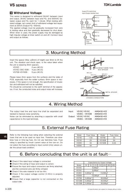
<strong>VS</strong> <strong>SERIES</strong>9 Withstand VoltageThis series is designed to withstand 2kVAC between inputand output, 2kVAC between input and FG, and 500VAC betweenoutput and FG, each for 1 minute. When testing withstandvoltage, set current limit of withstand voltage test equipmentat 20mA (Output-FG: 100mA).The applied voltage must be gradually increased from zeroto testing value and then gradually decreased for shut down.When timer is used, the power supply may be damaged byhigh impulse voltage at timer switch on and off. Connect inputand output as follows. 3. Mounting MethodInsert the spacer (Max φ8mm) of height over 8mm to lift theunit. The vibration and shock spec. is the value taken whenthe unit is raised by 8mm spacers.<strong>VS</strong>10C :2 pcs (Φ3.5)<strong>VS</strong>15C/30C/50B : 4 pcs (Φ3.5)<strong>VS</strong>75B-<strong>VS</strong>150B : 5 pcs (Φ3.5)Please leave 2mm space from the surfaces and the sides ofPCB, especially from the solder surface, 6mm space is necessary.If the space is not enough, the specification of insulationand withstand will not be satisfied.FG should be connected to the earth terminal of the apparatus.If not, the conducted noise and output noise will increase.4. Wiring MethodThe output load line and input line shall be separated andtwisted to improve noise sensitivity.Noise can be eliminated by attaching a capacitor with smallcapacitance to the load terminals.Input: <strong>VS</strong>10C/<strong>VS</strong>15C :AWG#30-#22<strong>VS</strong>30C - <strong>VS</strong>150B :AWG#22-#18Output: <strong>VS</strong>10C/<strong>VS</strong>15C :AWG#30-#22<strong>VS</strong>30C - <strong>VS</strong>150B :AWG#22-#185. External Fuse Rating<strong>VS</strong>Refer to the following fuse rating when selecting the externalfuses that are to be used on input line. Therefore use slowblowfuse or time-lug fuse. Do not use fast-blow fuse. Fuserating is specified by inrush current value at line turn-on. Donot select the fuse according to input current (rms) values underthe actual load condition.Model Fuse Value<strong>VS</strong>10C 1.5A<strong>VS</strong>15C 2A<strong>VS</strong>30C 3A<strong>VS</strong>50C 4AModel Fuse Value<strong>VS</strong>75B 5A<strong>VS</strong>100B 5A<strong>VS</strong>150B 6.3A6. Before concluding that the unit is at fault…A-326● Check if the rated input voltage is connected.● Check if the wiring of input and output is correct.● Ensure the input and output connectors are firmly attached,and the connector pins are firmly crimped.● Check if the wire material is not too thin.● Check if the output voltage control (V.ADJ) is properlyadjusted.● Ensure that a large capacitor is not connected on theoutput side.Capacitance by Output VoltageModel 3V 5V 12V 15V 24V 36V 48V<strong>VS</strong>10C 5,000µF −<strong>VS</strong>15C 5,000µF −<strong>VS</strong>30C 5,000µF 10,000µF<strong>VS</strong>50B 10,000µF −<strong>VS</strong>75B 5,000µF 30,000µF<strong>VS</strong>100B 5,000µF 30,000µF<strong>VS</strong>150B 5,000µF 30,000µF・All specifications are subject to change without notice.