
Create successful ePaper yourself
Turn your PDF publications into a flip-book with our unique Google optimized e-Paper software.
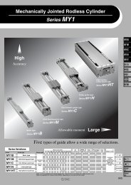
<strong>Compact</strong> <strong>Slide</strong><br />
<strong>Series</strong> <strong>MXU</strong><br />
ø6, ø10, ø16<br />
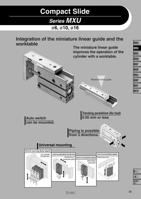
Integration of the miniature linear guide and the<br />
worktable<br />
The miniature linear guide<br />
improves the operation of the<br />
cylinder with a worktable.<br />
Miniature linear guide<br />
MXH<br />
<strong>MXU</strong><br />
MXS<br />
MXQ<br />
MXF<br />
MXW<br />
MXJ<br />
MXP<br />
MXY<br />
MTS<br />
Auto switch<br />
can be mounted.<br />
Traveling parallelism (No load)<br />
0.05 mm or less<br />
Piping is possible<br />
from 3 directions.<br />
Universal mounting<br />
Vertical mounting (Body tapped)<br />
3 in parallel<br />
(Dispenser)<br />
Lateral mounting (Body through-hole)<br />
Axial mounting (Body tapped)<br />
Transferring of Lateral mounting (Body tapped) Positioning of pin<br />
component parts<br />
Absorbing<br />
precisely<br />
D-<br />
-X<br />
Individual<br />
-X<br />
35
<strong>Series</strong> <strong>MXU</strong><br />
Model Selection<br />
Caution Theoretical output must be confirmed separately. Refer to the Theoretical Output on page 39.<br />
Selection Conditions: Follow the table below in order to determine selection conditions and then choose one selection graph.<br />
Vertical<br />
Horizontal<br />
l: Load eccentricity<br />
Mounting orientation<br />
m<br />
m<br />
L<br />
L<br />
Maximum speed mm/s<br />
Load eccentricity lmm<br />
Selection graph<br />
Up to 100 Up to 300<br />
—<br />
(1) (2)<br />
Up to 500<br />
(3)<br />
50<br />
(4)<br />
Up to 100<br />
100<br />
(5)<br />
200<br />
(6)<br />
50<br />
(7)<br />
Up to 300<br />
100<br />
(8)<br />
200<br />
(9)<br />
50<br />
(10)<br />
Up to 500<br />
100<br />
(11)<br />
200<br />
(12)<br />
∗ L: Overhang (the distance from the cylinder shaft center to the load center of gravity)<br />
The direction of L can also be a diagonal direction. (See the diagram on the right.)<br />
L<br />
Selection Graph (1) to (3) (Vertical Mounting)<br />
Cylinder shaft<br />
center<br />
m<br />
Load center<br />
of gravity<br />
Graph (1) Maximum speed: 100 (mm/s) or less<br />
Graph (3) Maximum speed: 500 (mm/s) or less<br />
1<br />
0.1<br />
Mass m (kg)<br />
0.1<br />
Mass m (kg)<br />
0.01<br />
0.001<br />
<strong>MXU</strong>16<br />
<strong>MXU</strong>6,10<br />
<strong>MXU</strong>16<br />
0.01<br />
<strong>MXU</strong>6,10<br />
5 20 40 60 80 100<br />
Overhang L (mm)<br />
0.0001<br />
5 20 40 60 80 100<br />
Overhang L (mm)<br />
Graph (2) Maximum speed: 300 (mm/s) or less<br />
1<br />
Mass m (kg)<br />
0.1<br />
0.01<br />
<strong>MXU</strong>16<br />
<strong>MXU</strong>6,10<br />
36<br />
0.001<br />
5 20 40 60 80 100<br />
Overhang L (mm)
<strong>Compact</strong> <strong>Slide</strong> <strong>Series</strong> <strong>MXU</strong><br />
Selection Graph (4) to (12) (Horizontal Mounting)<br />
Maximum speed: 100 (mm/s) or less<br />
Maximum speed: 300 (mm/s) or less<br />
Maximum speed: 500 (mm/s) or less<br />
Graph (4) Load eccentricity: 50 mm Graph (7) Load eccentricity: 50 mm Graph (10) Load eccentricity: 50 mm<br />
Mass m (kg)<br />
Mass m (kg)<br />
1<br />
0.1<br />
<strong>MXU</strong>16<br />
<strong>MXU</strong>6,10<br />
0.01<br />
0 20 40 60 80 100<br />
Mass m (kg)<br />
Overhang L (mm)<br />
Overhang L (mm)<br />
Overhang L (mm)<br />
Graph (5) Load eccentricity: 100 mm Graph (8) Load eccentricity: 100 mm Graph (11) Load eccentricity: 100 mm<br />
1<br />
0.1<br />
<strong>MXU</strong>16<br />
<strong>MXU</strong>6,10<br />
0.01<br />
0 20 40 60 80 100<br />
Mass m (kg)<br />
0.1<br />
0.01<br />
<strong>MXU</strong>16<br />
<strong>MXU</strong>6,10<br />
0.001<br />
0 20 40 60 80 100<br />
0.1<br />
0.01<br />
<strong>MXU</strong>16<br />
<strong>MXU</strong>6,10<br />
0.001<br />
0 20 40 60 80 100<br />
Mass m (kg)<br />
Mass m (kg)<br />
0.1<br />
0.01<br />
<strong>MXU</strong>16<br />
0.001<br />
<strong>MXU</strong>6,10<br />
0.0001<br />
0 20 40 60 80 100<br />
0.1<br />
0.01<br />
<strong>MXU</strong>16<br />
0.001<br />
<strong>MXU</strong>6,10<br />
0.0001<br />
0 20 40 60 80 100<br />
MXH<br />
<strong>MXU</strong><br />
MXS<br />
MXQ<br />
MXF<br />
MXW<br />
MXJ<br />
MXP<br />
MXY<br />
MTS<br />
Overhang L (mm)<br />
Overhang L (mm)<br />
Overhang L (mm)<br />
Graph (6) Load eccentricity: 200 mm Graph (9) Load eccentricity: 200 mm Graph (12) Load eccentricity: 200 mm<br />
0.1<br />
0.1<br />
0.1<br />
Mass m (kg)<br />
<strong>MXU</strong>16<br />
Mass m (kg)<br />
0.01<br />
<strong>MXU</strong>16<br />
Mass m (kg)<br />
0.01<br />
0.001<br />
<strong>MXU</strong>16<br />
<strong>MXU</strong>6,10<br />
<strong>MXU</strong>6,10<br />
0.01<br />
<strong>MXU</strong>6,10<br />
0 20 40 60 80 100<br />
Overhang L (mm)<br />
0.001<br />
0 20 40 60 80 100<br />
Overhang L (mm)<br />
0.0001<br />
0 20 40 60 80 100<br />
Overhang L (mm)<br />
Selection Example<br />
(1) Selection conditions<br />
Mounting: Vertical<br />
Max. speed: 500 mm/s<br />
Overhang: 10 mm<br />
Load mass: 0.01 Kg<br />
(2) Selection conditions<br />
Refer to Graph(3) based on vertical mounting and a speed of<br />
500 mm/s.<br />
In Graph (3), the intersection of a 10 mm overhang and load<br />
mass of 0.01 kg results in a determination of <strong>MXU</strong>16.<br />
Mounting: Vertical<br />
Max. speed: 500 mm/s<br />
Load eccentricity: 50 mm<br />
Overhang: 10 mm<br />
Load mass: 0.01 Kg<br />
Refer to Graph(10) based on horizontal mounting, a speed of<br />
500 mm/s and load eccentricity of 50 mm.<br />
In Graph (10), the intersection of a 10 mm overhang and load<br />
mass of 0.01 kg results in a determination of <strong>MXU</strong>16.<br />
37<br />
D-<br />
-X<br />
Individual<br />
-X
<strong>Compact</strong> <strong>Slide</strong><br />
<strong>Series</strong> <strong>MXU</strong><br />
How to Order<br />
<strong>MXU</strong> 10<br />
30<br />
M9BW<br />
S<br />
Made to Order<br />
Refer to page 39 for details.<br />
<strong>Compact</strong> slide<br />
Bore size<br />
6<br />
10<br />
16<br />
6 mm<br />
10 mm<br />
16 mm<br />
Number of auto switches<br />
Nil 2 pcs.<br />
S 1 pc.<br />
5<br />
10<br />
15<br />
20<br />
25<br />
30<br />
Stroke<br />
5 mm<br />
10 mm<br />
15 mm<br />
20 mm<br />
25 mm<br />
30 mm<br />
Auto switch<br />
Nil Without auto switch (Built-in magnet)<br />
∗ For the applicable auto switch model, refer to the table below.<br />
Applicable Auto Switch/Refer to pages 1719 to 1827 for further information on auto switches.<br />
Type<br />
Solid state<br />
switch<br />
Reed<br />
switch<br />
Special function<br />
—<br />
Diagnostic indication<br />
(2-color indication)<br />
—<br />
Electrical<br />
entry<br />
Grommet<br />
Grommet<br />
Load voltage Auto switch model<br />
Wiring<br />
(Output) DC AC Perpendicular In-line<br />
3-wire (NPN)<br />
3-wire (PNP)<br />
2-wire<br />
3-wire (NPN)<br />
3-wire (PNP)<br />
2-wire<br />
3-wire<br />
(NPN equivalent)<br />
2-wire<br />
24 V<br />
—<br />
24 V<br />
∗ Lead wire length symbols: 0.5 m ·········· Nil (Example) M9NW<br />
1 m ·········· M (Example) M9NWM<br />
3 m ·········· L (Example) M9NWL<br />
5 m ·········· Z (Example) M9NWZ<br />
Indicator light<br />
Yes<br />
Yes<br />
No<br />
5 V, 12 V<br />
12 V<br />
5 V, 12 V<br />
5 V<br />
12 V<br />
—<br />
—<br />
100 V<br />
100 V or less<br />
∗ Since there are other applicable auto switches than listed, refer to page 47 for details.<br />
∗ For details about auto switches with pre-wired connector, refer to pages 1784 and 1785.<br />
∗ Auto switches are shipped together (not assembled).<br />
12 V<br />
M9NV<br />
M9PV<br />
M9BV<br />
M9NWV<br />
M9PWV<br />
M9BWV<br />
A96V<br />
A93V<br />
A90V<br />
M9N<br />
M9P<br />
M9B<br />
M9NW<br />
M9PW<br />
M9BW<br />
A96<br />
A93<br />
A90<br />
Lead wired length (m)<br />
0.5<br />
(Nil)<br />
∗ Solid state auto switches marked with “<br />
1<br />
(M)<br />
—<br />
—<br />
—<br />
3<br />
(L)<br />
5<br />
(Z)<br />
—<br />
—<br />
—<br />
Pre-wired<br />
connector<br />
—<br />
—<br />
—<br />
Applicable load<br />
IC circuit<br />
—<br />
IC circuit<br />
—<br />
IC circuit<br />
—<br />
IC circuit<br />
Relay,<br />
PLC<br />
—<br />
Relay,<br />
PLC<br />
” are produced upon receipt of order.<br />
38
<strong>Compact</strong> <strong>Slide</strong> <strong>Series</strong> <strong>MXU</strong><br />
Specifications<br />
Symbol<br />
-XB13<br />
Made to Order Specifications<br />
(For details, refer to page 1865.)<br />
Specifications<br />
Low speed cylinder (5 to 50 mm/s)<br />
Bore size (mm)<br />
Fluid<br />
Action<br />
Piping port size<br />
Maximum operating pressure<br />
Proof pressure<br />
Ambient & fluid temperature<br />
Piston speed<br />
Lubrication<br />
Cushion<br />
Stroke length tolerance<br />
Auto switch (Option)<br />
Minimum Operating Pressure<br />
Bore size (mm)<br />
Min. operating pressure (MPa)<br />
6 10 16<br />
6<br />
0.12<br />
Air<br />
Double acting<br />
M5 x 0.8<br />
0.7 MPa<br />
1.05 MPa<br />
Without auto switch: –10 to +70°C<br />
With auto switch: –10 to +60°C<br />
50 to 500 mm/sec<br />
Non-lube<br />
Rubber bumper on both ends<br />
+1.0<br />
0<br />
Reed auto switch<br />
Solid state auto switch (2-wire, 3-wire)<br />
10<br />
0.06<br />
16<br />
0.06<br />
(MPa)<br />
MXH<br />
<strong>MXU</strong><br />
MXS<br />
MXQ<br />
MXF<br />
MXW<br />
MXJ<br />
MXP<br />
MXY<br />
Theoretical Output<br />
MTS<br />
(N)<br />
Bore size<br />
(mm)<br />
Rod size<br />
(mm)<br />
Operating<br />
direction<br />
Piston area<br />
(mm 2 )<br />
Operating pressure (MPa)<br />
0.3 0.5 0.7<br />
6<br />
3<br />
OUT<br />
IN<br />
28.3<br />
21.2<br />
8.49<br />
6.36<br />
14.2<br />
10.6<br />
19.8<br />
14.8<br />
10<br />
4<br />
OUT<br />
IN<br />
78.5<br />
66.0<br />
23.6<br />
19.8<br />
39.3<br />
33.0<br />
55.0<br />
46.2<br />
16<br />
6<br />
OUT<br />
IN<br />
201<br />
172<br />
60.3<br />
51.6<br />
101<br />
86.0<br />
141<br />
121<br />
Standard Stroke<br />
Bore size (mm)<br />
Standard stroke (mm)<br />
6, 10, 16<br />
5, 10, 15, 20, 25, 30<br />
∗ Refer to “Minimum Stroke for Auto Switch Mounting” on page 46.<br />
Mass<br />
(g)<br />
Model<br />
<strong>MXU</strong>6<br />
<strong>MXU</strong>10<br />
<strong>MXU</strong>16<br />
5<br />
66<br />
115<br />
216<br />
10<br />
72<br />
124<br />
215<br />
Cylinder stroke (mm)<br />
15 20<br />
81<br />
88<br />
138 147<br />
251 250<br />
25<br />
97<br />
166<br />
285<br />
30<br />
103<br />
174<br />
300<br />
D-<br />
-X<br />
Individual<br />
-X<br />
39
<strong>Series</strong> <strong>MXU</strong><br />
Allowable Moment<br />
Model Stroke<br />
5<br />
10<br />
15<br />
<strong>MXU</strong>6<br />
20<br />
25<br />
30<br />
5<br />
10<br />
15<br />
<strong>MXU</strong>10<br />
20<br />
25<br />
30<br />
5<br />
10<br />
15<br />
<strong>MXU</strong>16<br />
20<br />
25<br />
Allowable moment (N·m)<br />
M1<br />
0.046<br />
0.046<br />
0.061<br />
0.061<br />
0.076<br />
0.076<br />
0.047<br />
0.047<br />
0.080<br />
0.080<br />
0.103<br />
0.103<br />
0.115<br />
0.115<br />
0.153<br />
0.153<br />
0.190<br />
M2<br />
0.040<br />
0.040<br />
0.053<br />
0.053<br />
0.066<br />
0.066<br />
0.041<br />
0.041<br />
0.069<br />
0.069<br />
0.089<br />
0.089<br />
0.099<br />
0.099<br />
0.132<br />
0.132<br />
0.165<br />
M3<br />
0.049<br />
0.049<br />
0.062<br />
0.062<br />
0.074<br />
0.074<br />
0.109<br />
0.109<br />
0.169<br />
0.169<br />
0.212<br />
0.212<br />
0.296<br />
0.296<br />
0.380<br />
0.380<br />
0.464<br />
Correction value of<br />
moment center position<br />
distance (mm)<br />
Cp, Cy<br />
28.3<br />
28.3<br />
31.5<br />
34<br />
38.5<br />
41<br />
28.5<br />
31<br />
36<br />
38.5<br />
44<br />
46<br />
37.5<br />
37.5<br />
46<br />
46<br />
50<br />
Cr<br />
7.5<br />
9.5<br />
12<br />
Caution<br />
Precautions<br />
Be sure to read before handling.<br />
Refer to front matters 42 and 43 and<br />
pages 3 to 11 for Actuator and Auto<br />
Switch Precautions.<br />
1. Do not place your fingers in the clearance<br />
between the table and the cylinder tube.<br />
Your fingers could get caught between the<br />
table and the cylinder tube when the<br />
piston rod retracts.<br />
Because the cylinder outputs a great<br />
force, it could lead to injury if precautions<br />
are not taken to prevent your fingers from<br />
getting caught.<br />
2. In terms of the load weight and moment,<br />
the cylinder must be operated below the<br />
maximum load weight and allowable<br />
moment.<br />
3. If the output of the compact slide is applied<br />
directly to the table, make sure it is applied<br />
along the rod axial line. (Refer to the figure<br />
below.)<br />
30<br />
0.190<br />
0.165<br />
0.464<br />
52.5<br />
Expression of Calculation of Allowable Fp, Fy, Fr<br />
4. Make sure to connect a speed controller<br />
and adjust it to a speed of 500 mm/s or<br />
less to operate the cylinder.<br />
Pitch moment Yaw moment Roll moment<br />
Fp =<br />
M1 x 1000<br />
Lp+Cp+(St/2)<br />
M2 x 1000<br />
M3 x 1000<br />
(N) Fy =<br />
(N) Fr =<br />
(N)<br />
Ly+Cy+(St/2)<br />
Lr+Cr<br />
Lp: Distance between table and loading point (mm)<br />
Cp: Correction value of moment center position distance (mm)<br />
St: Stroke (mm)<br />
40<br />
Ly: Distance between table and loading point (mm)<br />
Cy: Correction value of moment center position distance (mm)<br />
St: Stroke (mm)<br />
Lr: Distance between table and loading point (mm)<br />
Cr: Correction value of moment center position distance (mm)
<strong>Compact</strong> <strong>Slide</strong> <strong>Series</strong> <strong>MXU</strong><br />
Mounting of <strong>Compact</strong> <strong>Slide</strong><br />
The compact slide can be mounted in four directions. Select the best<br />
direction according to the machine and work to be used.<br />
Lateral Mounting (Body through-hole)<br />
Mounting of Workpiece<br />
Workpieces can be mounted on 2 surfaces of the compact slide.<br />
The table is supported by miniature linear guide. Be careful not to apply<br />
strong impacts or excessive moments when mounting work.<br />
Hold the table when fastening workpieces to it with bolts, etc. If the<br />
body is held while tightening bolts, etc., the guide section will be<br />
subjected to a large moment, and there may be a loss of<br />
precision.<br />
MXH<br />
Model<br />
<strong>MXU</strong>6<br />
<strong>MXU</strong>10<br />
<strong>MXU</strong>16<br />
Bolt<br />
M3 x 0.5<br />
M4 x 0.7<br />
M4 x 0.7<br />
Maximum tightening torque (N·m)<br />
1.1<br />
2.5<br />
2.5<br />
Lateral Mounting (Body tapped)<br />
l1<br />
12.7<br />
15.6<br />
20.6<br />
When tightening the work on the table with bolts, it should be done<br />
while holding the table. If holding the body, it may cause more than<br />
allowable moment to the guide, leading to decrease in accuracy.<br />
For connection with a load having an external support/guide<br />
mechanism, select an appropriate connection method and perform<br />
careful alignment.<br />
Use caution, as scratches or nicks, etc. on the sliding parts of the piston<br />
rod can cause malfunction and air leakage.<br />
<strong>MXU</strong><br />
MXS<br />
MXQ<br />
MXF<br />
MXW<br />
MXJ<br />
Model<br />
<strong>MXU</strong>6<br />
<strong>MXU</strong>10<br />
<strong>MXU</strong>16<br />
Bolt<br />
M4 x 0.7<br />
M5 x 0.8<br />
M5 x 0.8<br />
Maximum tightening torque (N·m)<br />
2.5<br />
5.1<br />
5.1<br />
l1<br />
12.7<br />
15.6<br />
20.6<br />
l<br />
9.4<br />
11.2<br />
16.2<br />
Front Mounting<br />
MXP<br />
MXY<br />
MTS<br />
Vertical Mounting (Body tapped)<br />
Model<br />
<strong>MXU</strong>6<br />
<strong>MXU</strong>10<br />
<strong>MXU</strong>16<br />
Bolt<br />
M3 x 0.5<br />
M4 x 0.7<br />
M4 x 0.7<br />
Maximum tightening torque (N·m)<br />
1.1<br />
2.5<br />
2.5<br />
l<br />
5<br />
7<br />
9.5<br />
Top Mounting<br />
Model<br />
<strong>MXU</strong>6<br />
<strong>MXU</strong>10<br />
<strong>MXU</strong>16<br />
Bolt<br />
M3 x 0.5<br />
M4 x 0.7<br />
M4 x 0.7<br />
Maximum tightening torque (N·m)<br />
1.1<br />
2.5<br />
2.5<br />
l<br />
4.8<br />
6<br />
6<br />
Axial Mounting (Body tapped)<br />
Model<br />
<strong>MXU</strong>6<br />
<strong>MXU</strong>10<br />
<strong>MXU</strong>16<br />
Bolt<br />
M3 x 0.5<br />
M4 x 0.7<br />
M4 x 0.7<br />
Maximum tightening torque (N·m)<br />
1.1<br />
2.5<br />
2.5<br />
l<br />
5<br />
6<br />
6<br />
Operating Direction with Different Pressure Ports<br />
OUT port<br />
(2 on both sides)<br />
Order the plug below when changing the<br />
port position.<br />
Plug part no. (for replacement):<br />
CXS10-08-28747A<br />
OUT port<br />
D-<br />
Model<br />
<strong>MXU</strong>6<br />
<strong>MXU</strong>10<br />
<strong>MXU</strong>16<br />
Bolt<br />
M3 x 0.5<br />
M4 x 0.7<br />
M4 x 0.7<br />
Maximum tightening torque (N·m)<br />
1.1<br />
2.5<br />
2.5<br />
l<br />
4.8<br />
6<br />
6<br />
IN port<br />
(2 on both sides)<br />
IN port<br />
41<br />
-X<br />
Individual<br />
-X
<strong>Series</strong> <strong>MXU</strong><br />
Construction<br />
<strong>MXU</strong>6 (ø6)<br />
<strong>MXU</strong>10 (ø10)<br />
<strong>MXU</strong>16 (ø16)<br />
Component Parts<br />
No.<br />
1<br />
2<br />
Description<br />
Cylinder tube<br />
Head cover<br />
3 Piston<br />
4<br />
5<br />
6<br />
7<br />
8<br />
9<br />
10<br />
11<br />
12<br />
13<br />
Piston rod<br />
Miniature linear guide<br />
Table<br />
Bumper A<br />
Bumper B<br />
Bushing<br />
Steel ball A<br />
Steel ball B<br />
Type C retaining ring for hole<br />
Round head Phillips screw<br />
Material<br />
Aluminum alloy<br />
Brass<br />
Aluminum alloy<br />
Brass<br />
Aluminum alloy<br />
Stainless steel<br />
—<br />
Aluminum alloy<br />
Urethane<br />
Urethane<br />
Oil-impregnated sintered alloy<br />
High carbon chrome bearing steel<br />
High carbon chrome bearing steel<br />
Carbon tool steel<br />
Carbon steel<br />
Note<br />
Hard anodized<br />
ø6, ø10 Electroless nickel plated<br />
ø16 chromated<br />
ø6, ø10<br />
ø16<br />
Hard anodized<br />
Oil impregnated<br />
Phosphate coated<br />
Component Parts<br />
No.<br />
14<br />
15<br />
16<br />
17<br />
18<br />
19<br />
20<br />
21<br />
22<br />
Description<br />
Hexagon socket head cap screw<br />
Hexagon socket head plug<br />
Rod end nut<br />
Magnet<br />
Magnet holder<br />
Piston gasket<br />
Rod seal<br />
Piston seal<br />
Gasket<br />
Material<br />
Chromium molybdenum steel<br />
Chromium molybdenum steel<br />
Carbon steel<br />
—<br />
—<br />
Brass<br />
NBR<br />
NBR<br />
NBR<br />
NBR<br />
∗ <strong>Series</strong> <strong>MXU</strong> cannot be disassembled.<br />
Note<br />
Nickel plated<br />
Nickel plated<br />
Nickel plated<br />
ø6, ø10<br />
ø16<br />
42
<strong>Compact</strong> <strong>Slide</strong> <strong>Series</strong> <strong>MXU</strong><br />
Dimensions: <strong>MXU</strong>6 (ø6)<br />
2 x M3 x 0.5<br />
Depth 5<br />
MXH<br />
<strong>MXU</strong><br />
3 x M4 x 0.7 through<br />
Bottom hole dia. ø3.3<br />
6 x ø6 counterbore depth 3.3<br />
Plug for port (Hexagon socket head set screw)<br />
4 x M5 x 0.8 x 4 l 2 x M5 x 0.8<br />
MXS<br />
MXQ<br />
4 x M3 x 0.5<br />
Depth 5<br />
4 x M3 x 0.5<br />
Depth 4.8<br />
MXF<br />
MXW<br />
MXJ<br />
MXP<br />
MXY<br />
MTS<br />
4 x M3 x 0.5<br />
Depth 4.8<br />
Stroke (mm)<br />
5<br />
10<br />
15<br />
20<br />
25<br />
30<br />
BS<br />
10<br />
15<br />
20<br />
25<br />
30<br />
35<br />
LS<br />
20<br />
20<br />
25<br />
30<br />
40<br />
40<br />
NS<br />
14<br />
14<br />
24<br />
24<br />
34<br />
34<br />
S<br />
37.5<br />
42.5<br />
47.5<br />
52.5<br />
57.5<br />
62.5<br />
Z<br />
46<br />
51<br />
56<br />
61<br />
66<br />
71<br />
TS<br />
45.5<br />
50.5<br />
55.5<br />
60.5<br />
65.5<br />
70.5<br />
D-<br />
-X<br />
Individual<br />
-X<br />
43
<strong>Series</strong> <strong>MXU</strong><br />
Dimensions: <strong>MXU</strong>10 (ø10)<br />
2 x M4 x 0.7<br />
Depth 6<br />
4 x M4 x 0.7<br />
Depth 7<br />
3 x M5 x 0.8 through<br />
Bottom hole dia. ø4.3<br />
6 x ø7.5 counterbore depth 4.4<br />
Plug for port (Hexagon socket head set screw)<br />
4 x M5 x 0.8 x 4 l 2 x M5 x 0.8<br />
4 x M4 x 0.7<br />
Depth 6<br />
4 x M4 x 0.7<br />
Depth 6<br />
Stroke (mm)<br />
5<br />
10<br />
15<br />
20<br />
25<br />
30<br />
BS<br />
10<br />
14<br />
18<br />
24<br />
32<br />
35<br />
LS<br />
14<br />
19<br />
25<br />
30<br />
40<br />
45<br />
NS<br />
14<br />
14<br />
24<br />
24<br />
34<br />
34<br />
S<br />
41.5<br />
46.5<br />
51.5<br />
56.5<br />
64.5<br />
68.5<br />
Z<br />
53<br />
58<br />
63<br />
68<br />
76<br />
80<br />
TS<br />
52.5<br />
57.5<br />
62.5<br />
67.5<br />
75.5<br />
79.5<br />
44
<strong>Compact</strong> <strong>Slide</strong> <strong>Series</strong> <strong>MXU</strong><br />
Dimensions: <strong>MXU</strong>16 (ø16)<br />
MXH<br />
2 x M4 x 0.7<br />
Depth 6<br />
<strong>MXU</strong><br />
4 x M4 x 0.7<br />
Depth 9.5<br />
3 x M5 x 0.8 through<br />
Bottom hole dia. ø4.3<br />
6 x ø7.5 counterbore depth 4.4<br />
Plug for port (Hexagon socket head set screw)<br />
4 x M5 x 0.8 x 4 l<br />
4 x M4 x 0.7<br />
Depth 6<br />
2 x M5 x 0.8<br />
MXS<br />
MXQ<br />
MXF<br />
MXW<br />
MXJ<br />
MXP<br />
MXY<br />
MTS<br />
4 x M4 x 0.7<br />
Depth 6<br />
Stroke (mm)<br />
5<br />
10<br />
15<br />
20<br />
25<br />
30<br />
BS<br />
20<br />
20<br />
30<br />
30<br />
40<br />
45<br />
LS<br />
24<br />
24<br />
35<br />
35<br />
45<br />
50<br />
NS<br />
24<br />
24<br />
34<br />
34<br />
40<br />
40<br />
S<br />
52<br />
52<br />
62<br />
62<br />
72<br />
77<br />
Z<br />
66<br />
66<br />
76<br />
76<br />
86<br />
91<br />
TS<br />
65.5<br />
65.5<br />
75.5<br />
75.5<br />
85.5<br />
90.5<br />
D-<br />
-X<br />
Individual<br />
-X<br />
45
<strong>Series</strong> <strong>MXU</strong><br />
Auto Switch Proper Mounting Position (Detection at Stroke End) and Its Mounting Height<br />
D-A9<br />
D-M9<br />
D-M9W<br />
( ): Denotes the values of D-A93.<br />
D-A9V<br />
D-M9V<br />
D-M9WV<br />
( ): Denotes the values of D-A9V.<br />
Bore<br />
size<br />
6<br />
10<br />
16<br />
Application<br />
stroke<br />
D-A9, D-A9V<br />
A<br />
B<br />
W<br />
A<br />
5 to 30<br />
5 to 20<br />
25<br />
30<br />
5<br />
10<br />
13<br />
13<br />
16<br />
15<br />
23<br />
18<br />
0<br />
3.5<br />
2.5(5)<br />
–1.5<br />
(1)<br />
17<br />
17<br />
20<br />
19<br />
27<br />
22<br />
3.5<br />
7.5<br />
6.5<br />
2.5<br />
17<br />
17<br />
20<br />
19<br />
27<br />
22<br />
3.5<br />
7.5<br />
4.5<br />
0.5<br />
15 23<br />
27<br />
27<br />
4 –2<br />
8 2<br />
20 18<br />
22<br />
22<br />
8 0<br />
25<br />
30<br />
23<br />
23<br />
(0.5) 27<br />
27<br />
27<br />
27<br />
Note 1) Negative figures in the table W indicate an auto switch is mounted<br />
inward from the edge of the cylinder body.<br />
Note 2) In the case of models with 5 and 10 strokes, the switch may not turn off<br />
within the operation range or two switches may turn on simultaneously.<br />
Fix switches outside 1 to 4 mm further than the values in the above<br />
table (if 1 switch is used, make sure that it turns ON and OFF properly;<br />
if 2 switches are used, make sure that both switches turn ON).<br />
Note 3) ( ) in column W is the dimensions of D-A93.<br />
Minimum Stroke for Auto Switch Mounting<br />
No. of<br />
auto switches<br />
mounted<br />
1 pc.<br />
2 pcs.<br />
(mm)<br />
D-M9, D-M9W D-M9V, D-M9WV<br />
(mm)<br />
Applicable auto switch model<br />
D-A9 D-M9 D-M9W<br />
D-A9V D-M9V D-M9WV<br />
5<br />
10<br />
5<br />
5<br />
5<br />
10<br />
B<br />
W<br />
A<br />
B<br />
W<br />
Auto Switch Groove Position<br />
Bore size<br />
6<br />
10<br />
16<br />
A<br />
10<br />
14<br />
19<br />
4 x ø4.2<br />
(mm)<br />
B<br />
6.9<br />
8.8<br />
13.9<br />
Operating Range<br />
Auto switch model<br />
D-A9/A9V<br />
D-M9/M9V<br />
D-M9W/M9WV<br />
6<br />
5<br />
3<br />
Bore size (mm)<br />
10<br />
6<br />
3.5<br />
16<br />
9<br />
4.5<br />
∗ Since this is a guideline including hysteresis, not<br />
meant to be guaranteed. (assuming approximately<br />
±30% dispersion.) There may be the case it will vary<br />
substantially depending on an ambient environment.<br />
46
<strong>Compact</strong> <strong>Slide</strong> <strong>Series</strong> <strong>MXU</strong><br />
Auto Switch Mounting<br />
Watchmaker’s screwdriver<br />
Auto switch<br />
mounting screw<br />
Auto switch<br />
Tightening Torque of Auto Switch Mounting Screw<br />
(N•m)<br />
Auto switch mounting Tightening torque<br />
D-A9 (V)<br />
0.10 to 0.20<br />
D-M9 (V)<br />
0.05 to 0.15<br />
D-M9W(V)<br />
Caution on Installing in Close Proximity to Each Other<br />
When tightening the auto switch mounting<br />
screw, use a watchmaker’s screwdriver with<br />
a handle about 5 to 6 mm in diameter.<br />
Note) When used with side piping, it is not<br />
possible to mount a D-A9V, M9V<br />
auto switch type on the side to which<br />
the piping is connected.<br />
MXH<br />
<strong>MXU</strong><br />
MXS<br />
MXQ<br />
MXF<br />
MXW<br />
MXJ<br />
MXP<br />
MXY<br />
MTS<br />
When compact slide cylinders equipped with D-A9 or D-M9 auto switches<br />
are used, the auto switches could activate unintentionally if the installed<br />
distance is less than the dimension shown in Table (1). Therefore, make sure<br />
to provide at least this much clearance. Due to unavoidable circumstances, if<br />
they must be used with less distance than the dimensions given in the table<br />
below, the cylinders must be shielded. Therefore, affix a steel plate or a<br />
magnetic shield plate (MU-S025) to the area on the cylinder that corresponds<br />
to the adjacent auto switch. (Please contact <strong>SMC</strong> for details.) The auto switch<br />
could activate unintentionally if a shield plate is not used.<br />
d<br />
Table (1)<br />
Bore size (mm)<br />
<strong>MXU</strong>6<br />
<strong>MXU</strong>10<br />
<strong>MXU</strong>16<br />
d<br />
5<br />
5<br />
10<br />
(mm)<br />
L<br />
21<br />
25<br />
35<br />
L<br />
Dimensions of shield plate (MU-S025) that is sold separately are<br />
indicated as reference.<br />
18<br />
36<br />
Material: Ferrite stainless steel, Thickness: 0.3 mm<br />
Since the back side is treated with adhesive, it is possible to attach to the cylinder.<br />
Other than the applicable auto switches listed in “How to Order”, the following auto switches can be mounted.<br />
∗ Normally closed (NC= b contact), solid state switch (D-F9G/F9H type) are also available. For details, refer to page 1746.<br />
D-<br />
-X<br />
Individual<br />
-X<br />
47