modular clamping technology - OTT-Jakob Spanntechnik GmbH
modular clamping technology - OTT-Jakob Spanntechnik GmbH
modular clamping technology - OTT-Jakob Spanntechnik GmbH

You also want an ePaper? Increase the reach of your titles
YUMPU automatically turns print PDFs into web optimized ePapers that Google loves.
MODULAR CLAMPING TECHNOLOGY<br />
LET OUR EXPERIENCE WORK FOR YOU
You can rely on us.<br />
We offer you the service that you can<br />
expect from the leader in <strong>technology</strong>.<br />
Selling good products is not enough.<br />
We also provide our customers with<br />
fast and efficient support so they are<br />
able to run their production without<br />
delays.<br />
Our technical support team is always<br />
there for you and will answer your<br />
most difficult and complex questions.<br />
You find local hotline support in our<br />
sales offices all around the world and<br />
our main office in Lengenwang is also<br />
prepared to help you:<br />
Call: <strong>OTT</strong>-JAKOB/Lengenwang:<br />
+49 83 64/98 21- 0 · www.Ott-<strong>Jakob</strong>.de<br />
II
CONTENTSINHALT<br />
Power drawbars for steep taper tools<br />
SK<br />
• SK-30 gripper / Inside spindle intensifier 3 - 5<br />
• SK-40 gripper / Inside spindle intensifier 7 - 11<br />
• SK-50 gripper / Inside spindle intensifier 13 - 18<br />
• SK-50 reinforced design 19<br />
• SK-60 gripper / Inside spindle intensifier 20 - 21<br />
• Technical data 22 - 23<br />
HSK-<strong>clamping</strong> units for tools according to DIN 69893<br />
HSK<br />
• HSK-<strong>clamping</strong> units for form A / Inside spindle intensifier 2 - 3<br />
• Inner contour for form A 4<br />
• Technical data for inner contour 5<br />
• HSK-<strong>clamping</strong> units for form B / Inside spindle intensifier 6 - 7<br />
• Inner contour for form B 8<br />
• Technical data for inner contour 9<br />
• HSK-<strong>clamping</strong> units for form E / Inside spindle intensifier 10 - 11<br />
• Inner contour for form E 12<br />
• Technical data for inner contour 13<br />
• HSK-<strong>clamping</strong> units for form F / Inside spindle intensifier 14 - 15<br />
• Inner contour for form F 16<br />
• Technical data for inner contour 17<br />
• HSK-<strong>clamping</strong> units for form AB / Inside spindle intensifier 18 - 19<br />
• Inner contour for form AB 20<br />
• Technical data for inner contour 21<br />
• Technical data 22 - 23<br />
• Inner contour for medium transfer 4 24<br />
Unclamp units (LE) and rotary unions (DDF)<br />
LE/DDF<br />
• LE 60 - hydr. LE with air blast connection 2<br />
• LE 92 - hydr. LE with air blast connection 3<br />
• LE 95 - hydr. LE with connection for single-passage rotary union 4<br />
• LE 95-B - hydr. LE with connection for single-passage DDF incl. air blast connection 5<br />
• LE 95 - hydr. LE with longer grippers (position indication) 6<br />
• LE 102-B - hydr. LE with connection for single-passage DDF incl. air blast connection 7<br />
• LE 133 - hydr. LE with connection for single-passage DDF incl. air blast connection 8<br />
• LE 95-F - hydr. LE with connection for single passage DDF (fixed flange) 9<br />
• LE 115 - hydr. LE with connection for single passage DDF (fixed flange) 10<br />
• LE 124-F-B - hydr. LE with connection for single passage DDF (fixed flange) 11<br />
• LE 150-P - pneumatic LE 12<br />
• LE 150-PA - pneumatic LE with connection for single-passage rotary union 13<br />
• LE 119-P - pneumatic LE (connection for single-passage rotary union optional) 14<br />
• DDF for hydraulic un<strong>clamping</strong> 15<br />
• Dual-passage DDF for hydr. un<strong>clamping</strong> and cleaning of the tool interface with air 16<br />
• Dual-passage DDF for hydr. un<strong>clamping</strong> and air for cleaning and during rotation 17<br />
• Dual-passage DDF for hydr. un<strong>clamping</strong>, coolant supply and cleaning with air blast 18<br />
• Dual-passage DDF for hydr. un<strong>clamping</strong>, coolant supply, air blast and signal ring 19<br />
• Single-passage DDF (36.000 RPM) for <strong>OTT</strong>-JAKOB LE - radial connection 20<br />
• Single-passage DDF (36.000 RPM) for <strong>OTT</strong>-JAKOB LE - axial connection 21<br />
• Single-passage DDF (16.000 RPM) for <strong>OTT</strong>-JAKOB LE - radial connection 22<br />
• Single-passage DDF (16.000 RPM) for <strong>OTT</strong>-JAKOB LE - axial connection 23<br />
III
SEIT 1873 HISTORY<br />
SINCE 1873<br />
We combine traditional values like<br />
striving for perfection and precision<br />
with our commitment to innovation.<br />
New inventions and patents in all<br />
areas are the results.<br />
Innovative competence is an <strong>OTT</strong>-JAKOB<br />
tradition.<br />
Our company goes back to 1873 when<br />
Albert Ott founded the Mathematical-<br />
Mechanical Institute in Kempten<br />
1880 - World exhibition in Melbourne<br />
1897 - Exhibition in Chicago<br />
In 1974 we developed the power<br />
drawbar, which has been continuously<br />
improved to meet new application<br />
requirements. Today, 250,000<br />
machines worldwide are operating with<br />
the Ott power drawbar.<br />
On March 1, 1993 the company<br />
Ott-<strong>Spanntechnik</strong> merged with the<br />
<strong>Jakob</strong> Group.<br />
<strong>OTT</strong>-JAKOB <strong>Spanntechnik</strong> was born.<br />
1998 - We are celebrating 125 years of<br />
world-renowned capability in precision<br />
mechanics and tool <strong>clamping</strong><br />
<strong>technology</strong>.<br />
A small company made its way to<br />
become the leading manufacturer of<br />
automatic tool <strong>clamping</strong> systems.<br />
IV
UNSER DENKEN PHILOSOPHY<br />
OUR THINKING<br />
In the past years <strong>OTT</strong>-JAKOB could further<br />
develop its leading position in tool <strong>clamping</strong><br />
<strong>technology</strong>.<br />
Out of this position we entered the following<br />
commitments:<br />
1. Our highly motivated and trained employees<br />
produce customer oriented high-tech products<br />
in best quality. Know-how, team spirit and<br />
innovative power are the most important<br />
components for developing high-end <strong>clamping</strong><br />
<strong>technology</strong> products for mechanical engineering<br />
2. All <strong>OTT</strong>-JAKOB product lines guarantee the<br />
optimum in system safety on the highest level<br />
of technological development.<br />
V
TRENDSERKENNEN<br />
RECOGNIZING<br />
A shorter Time-to-Market ratio secures<br />
your investments. But first one has to<br />
recognize the trends.<br />
Our Research & Development<br />
department cooperates with universities<br />
and research teams to develop customer<br />
oriented system solutions, which build<br />
trends for the future.<br />
Sensational test results:<br />
Our plant in Lengenwang tested several<br />
<strong>clamping</strong> units.<br />
The units were successfully clamped and<br />
released up to 9 million times with a<br />
speed of 0.13 seconds.<br />
VI
PERFEKTIONFERTIGEN<br />
FINISHING<br />
The employee and his<br />
knowledge are the<br />
center of attention<br />
Ott employees have years of<br />
experience and are innovative.<br />
They are familiar with complex<br />
speed calculations and<br />
limitations thereof for machine<br />
tool applications, necessary<br />
unclamp forces and other<br />
parameters.<br />
High-tech manufacturing<br />
machines and latest CAD<br />
software are employed with<br />
perfection.<br />
Years of experience,<br />
cooperation with leading<br />
machine and spindle manufacturers,<br />
internationally recognized<br />
competence and cooperation<br />
with universities in the<br />
development of standards<br />
maximise our performance.<br />
<strong>OTT</strong>-JAKOB maintains a close<br />
contact with engineers in<br />
research and development.<br />
This guarantees user-specific<br />
products, which work efficiently<br />
in practical applications.<br />
<strong>OTT</strong>-JAKOB –<br />
Success through perfection.<br />
VII
COMPLETESYSTEMS<br />
Standardization requires meeting the needs of the<br />
user. The Ott universal inside spindle contour is an<br />
important step towards <strong>modular</strong> tooling.<br />
It offers the manufacturer of machines and/or spindle<br />
units the ability to clamp different steep taper tools<br />
(taper/retention knob standard) simply by exchanging<br />
the gripper unit.<br />
We would like you to benefit from this advantage.<br />
Several variations of power drawbars with or without<br />
coolant, with hydraulic or pneumatic unclamp units<br />
can be built into the same spindles.<br />
Rotary unions and unclamp units are compatible and<br />
exchangeable.<br />
VIII<br />
We offer high performance at a fair price.
Due to recent innovations, we can<br />
now offer a complete program of<br />
HSK- and steep taper power<br />
drawbars. This makes <strong>OTT</strong>-JAKOB<br />
the only manufacturer who offers<br />
complete tool <strong>clamping</strong> systems.<br />
The impressive number of different modules<br />
with all necessary adaptations to customers<br />
and standards show the advantages of<br />
customer and user oriented product<br />
development.<br />
Take advantage of our professional design<br />
and engineering department to optimize your<br />
products and minimize your cost.<br />
IX
Minimalmengenschmierung:<br />
MINIMUM VOLUME LUBRICATION<br />
The latest technique of using minimum volumes of<br />
coolant for dry operations has become a focal point in<br />
the manufacturing industry. Ott-<strong>Jakob</strong> offers two<br />
variations for all HSK-<strong>clamping</strong> units:<br />
Internal<br />
External minimum volume lubrication<br />
Using external MMKS, the aerosol is produced in<br />
a special mixing device outside the spindle.<br />
Like coolant, the mixture is fed through a rotary<br />
union. <strong>OTT</strong>-JAKOB offers three variations of rotary<br />
unions to be used for external minimum volume<br />
lubrication for <strong>OTT</strong>-JAKOB HSK-<strong>clamping</strong> units:<br />
• Dual-passage rotary union<br />
(max. 10.000 RPM – mixed externally<br />
p max = 5 bar)<br />
• Single-passage rotary union GDR for<br />
<strong>OTT</strong>-JAKOB unclamp units (max. 16.000<br />
RPM – mixed externally p max = 5 bar)<br />
• Single-passage rotary union GD for<br />
<strong>OTT</strong>-JAKOB unclamp units (max. 36.000<br />
RPM – mixed externally p max = 5 bar)<br />
External<br />
Internal minimum volume lubrication<br />
Using internal MMKS, the air-lubrication mixture<br />
is produced inside the spindle. Air and minimum<br />
amounts of lubrication are fed separately into<br />
the spindle through the <strong>OTT</strong>-JAKOB HSK-<strong>clamping</strong><br />
unit.<br />
They are mixed directly in front of the tool<br />
interface. Changing the mixture ratio allows<br />
for a quick adjustment of the aerosol doses.<br />
You can rely on us - in every situation!<br />
Both systems can be integrated as modules into<br />
existing as well as new HSK-<strong>clamping</strong> units.<br />
X
HSC - High Speed Cutting:<br />
Accelerated machining in the machine tool and mold<br />
making industry and in the cutting industry through<br />
High-Speed-Cutting (HSC) requires solutions for faster<br />
tool change.<br />
<strong>OTT</strong>-JAKOB's new <strong>clamping</strong> units, rotary unions and<br />
unclamp units meet these requirements.<br />
A shorter tool changing<br />
time represents a constant<br />
challenge, which<br />
even increased with<br />
HSC-manufacturing.<br />
Fast working automatic<br />
<strong>clamping</strong> systems are<br />
necessary which have<br />
to be more accurate,<br />
rigid and universal than<br />
conventional systems.<br />
<strong>OTT</strong>-JAKOB met these<br />
requirements by developing<br />
a complete new<br />
HSC-<strong>clamping</strong> unit.<br />
<strong>OTT</strong>-JAKOB has the necessary know-how<br />
The table below shows the maximum RPM and the<br />
minimum length for HSK power drawbars:<br />
HSK Power Drawbar<br />
(Revision 01/01)<br />
Size Length from RPM up to<br />
HSK E 25<br />
HSK A/E 32 B 40<br />
HSK A/E 40 B/F 50<br />
HSK A/E 50 B/F 63<br />
HSK A/E 63 B/F 80<br />
HSK A 80 / B 100<br />
HSK A 100 / B 125<br />
HSK A 125 / B 160<br />
HSK E 160<br />
211 mm 80.000 min-1<br />
208 mm<br />
252 mm<br />
222 mm<br />
232 mm<br />
229 mm<br />
320 mm<br />
575 mm<br />
451 mm<br />
60.000 min-1<br />
50.000 min-1<br />
45.000 min-1<br />
40.000 min-1<br />
24.000 min-1<br />
18.000 min-1<br />
6.000 min-1<br />
200 min-1<br />
We are happy to answer your questions<br />
regarding HSC.<br />
XI
POWERCHECK<br />
All SK work holders from<br />
SK30 to SK60<br />
(DIN/ISO/ANSI) and all HSK<br />
work holders according to DIN<br />
69893 (HSK-A 32/B 40 to<br />
HSK-A 125/B 160) can be<br />
used.<br />
Conventional gages measure<br />
in accordance to the nominal<br />
component dimension. The<br />
manufacturing related tolerance<br />
range of the components<br />
could cause a false<br />
measuring result. The power<br />
check offers the possibility<br />
to take these tolerances into<br />
consideration during the<br />
measuring process!<br />
The critical guard<br />
The pull force gage "Power<br />
Check" minimizes the down<br />
times for your machines.<br />
It is a compact unit with power<br />
supply and adjustable tolerance<br />
range, which should not be<br />
missing in any production facility.<br />
The Power Check measures the<br />
pull force of your machines fast<br />
and reliable and prevents tool<br />
breaking and down times.<br />
Rely on <strong>OTT</strong>-JAKOB for the safety<br />
of your production!<br />
The LCD-display shows the<br />
actual <strong>clamping</strong> force.<br />
Display of the measuring<br />
results in Newton and<br />
Kilopound.<br />
XII
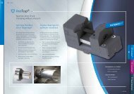
KÜRZESTER SK-50 SPANNER<br />
SHORTEST SK-50 GRIPPER<br />
Highest Precision in smallest Space<br />
<strong>OTT</strong>-JAKOB has been designing and<br />
manufacturing Power Drawbars for<br />
the machine tool industry for over<br />
25 years.<br />
In the area of Steep Tapers, the<br />
traditional manufacturer from Bavaria<br />
has just developed a SK-50 Power<br />
Drawbar with a sensational short<br />
spindle of 298 mm lenght.<br />
Because of these new dimensions,<br />
new manufacturing methods became<br />
feasible of which machine tool<br />
designers in the past could only<br />
dream. This short spindle length of<br />
298 mm allows for optimum flexibility<br />
and space saving.<br />
5-axis heads, as well as nutating<br />
heads, can now be built more<br />
compact.<br />
As spindle speed of 6,000 RPM<br />
and a pull force of 15,000 N<br />
(3,370 Ibs)<br />
are features which can be<br />
advantageously utilized<br />
for extreme applications.<br />
Secure tool retention<br />
at extreme cutting<br />
conditions at any angle<br />
position can be realized.<br />
The coolant/air supply is<br />
possible through single or<br />
double passage rotary unions.<br />
The assembly of the <strong>OTT</strong>-JAKOB Power<br />
Drawbars can be done easily and<br />
quickly by average personnel.<br />
Thanks to the <strong>OTT</strong>-JAKOB universal<br />
contour....<br />
.... the use of the most known standard<br />
tooling ist guaranteed:<br />
• DIN 61871 / 69872<br />
• ANSI B5.50<br />
• ISO 7388/1/2 Typ A<br />
• ISO 7388/1/2 Typ B<br />
• MAS 403-1982 BT/PT 2 (30°)<br />
• MAS 403-1982 BT/PT 1 (45°)<br />
XIII
<strong>OTT</strong>-JAKOB HILFSGERÄTE<br />
ACCESSORIES<br />
E.M. ±0,1<br />
un<strong>clamping</strong> position<br />
Steep taper assembly tool for<br />
gripper units<br />
The <strong>OTT</strong>-JAKOB steep taper<br />
assembly tool allows for an easy<br />
gripper change or adjustment to<br />
the setting dimension. This tool<br />
is available in all steep taper<br />
sizes from SK30 to SK60.<br />
HSK assembly tool for <strong>clamping</strong><br />
units<br />
The assembly tool facilitates the<br />
mounting of the <strong>clamping</strong> unit.<br />
It is available in all HSK sizes from<br />
HSK E 25 to HSK A 160.<br />
l 1<br />
Gage for HSK spindle edge<br />
The <strong>OTT</strong>-JAKOB gage for HSK<br />
spindle edge enables an easy<br />
determination of the dimension<br />
l1. The gage is available in all<br />
HSK sizes from HSK E 25 to<br />
HSK A 160.<br />
XIV
Nomenclature - Information<br />
We developed a new nomenclature system to be able to define complete tool <strong>clamping</strong> systems before<br />
the actual design process. This system characterizes the single modules and assembly units:<br />
-> Form of the power drawbar<br />
-> High-speed unit<br />
-> Nominal size of the interface<br />
-> Code of the interface standard<br />
-> Medium transfer<br />
-> Extension<br />
-> Position indication<br />
-> Unclamp unit<br />
-> Rotary union<br />
➨<br />
➨<br />
➨<br />
➨<br />
➨<br />
➨<br />
➨<br />
➨<br />
➨<br />
➨<br />
➨<br />
–<br />
-> Spindle length (mm)<br />
➨<br />
The following pages describe the different variations. All other forms are special designs and not part of this<br />
standard catalog:<br />
Example: Nomenclature for steep taper power drawbars<br />
• Spindle integrated steep taper power drawbar for steep taper tooling size ISO-40 (DIN 69871/2) SK 7 - 11<br />
• Central coolant supply<br />
• Position indication with signal ring at the diameter of the spindle shaft<br />
• Without unclamp unit<br />
• Dual-passage rotary union for hydraulic un<strong>clamping</strong> of power drawbars and central coolant DDF 20<br />
supply or cleaning of the tool interface with air during tool change<br />
• Spindle length: 550.0 mm<br />
I S – 4 0 – A 1 – 2 – G – 0 0 2 5 – 0 5 5 0 , 0<br />
Example: Nomenclature for HSK-<strong>clamping</strong> units<br />
• HSK-high speed units for tooling size HSK-A100 (DIN 69893) HSK 2 - 5<br />
• Central coolant supply / radial air blast for cleaning the interface HSK 24<br />
• One-piece drawbar shaft extension<br />
• LE 95 with longer grippers - hydraulic unclamp unit with connection for single-passage rotary union LE 6<br />
position indication<br />
• Single-passage high speed rotary union GD with closed seal unit to be used in DDF 22<br />
<strong>OTT</strong>-JAKOB unclamp units (max. 36,000 RPM - 80 bar KSM-pressure)<br />
• Spindle length: 1.082,5 mm<br />
I F H 1 0 0 A K – 4 V K – 0 5 2 1 – 1 0 8 2 , 5<br />
XV
Form of the power drawbar<br />
1 2<br />
Nomenclature position<br />
A<br />
E<br />
I<br />
I<br />
S<br />
S<br />
S<br />
F<br />
Power drawbar for steep taper tools<br />
Power drawbar<br />
Inside spindle drawbar<br />
Spindle integrated power drawbar<br />
HSK-<strong>clamping</strong> units<br />
Spindle integrated spring loaded power drawbar<br />
1 2 3 4 5 6 7 8 9 10 11 12 13 14 15 16 17 18 19 20 21 22 23 24<br />
,<br />
A S Power Drawbar<br />
The complete power drawbar (spring stack, patented intensifying mechanism, piston, etc) is built into an<br />
added-on cylinder outside the spindle shaft to accomodate a short and narrow spindle:<br />
E S Inside spindle drawbar<br />
Intensifying mechanism and piston are built into an added-on cylinder outside the spindle shaft.<br />
The spring stack is built inside the spindle shaft. A signal ring enables position indication at the end<br />
of the spindle:<br />
XVI
I S Spindle integrated power drawbar<br />
The complete power drawbar is built into the spindle shaft. This form is used mainly for higher RPM:<br />
Function:<br />
Grippers with preloaded spring stacks or special springs and standard retention knobs pull the cutting<br />
tools into the spindle. A special intensifying mechanism amplifies the spring force of <strong>OTT</strong>-JAKOB steep<br />
taper power drawbars. The <strong>clamping</strong> system is locked at the same time. The pull force is a measure<br />
for the transmittable horsepower or torque of the motor. The compact design of the Ott-<strong>Jakob</strong> power<br />
drawbars offers high pull forces and system safety in the smallest installation spaces.<br />
I F Spindle integrated spring loaded power drawbar<br />
HSK-<strong>clamping</strong> units use only one form, similar to the IS-form for steep taper power drawbars:<br />
Function:<br />
During <strong>clamping</strong> of the hollow shaft taper (HSK), the <strong>clamping</strong> cone of the <strong>clamping</strong> unit presses the<br />
gripper segments radially to the outside. The spindle and the tool support the gripper segments. They<br />
pull the oversize hollow shaft taper into the spindle and clamp it against the axial face of the spindle.<br />
The patented design of the <strong>OTT</strong>-JAKOB HSK-<strong>clamping</strong> units amplifies the spring force of the intensifier.<br />
The friction between the taper and the face contact as well as the keyways transmit the torque.<br />
Spring stack or special springs generate the pull force.<br />
XVII
High-speed unit<br />
3<br />
H<br />
Nomenclature position<br />
High-speed unit<br />
1 2 3 4 5 6 7 8 9 10 11 12 13 14 15 16 17 18 19 20 21 22 23 24<br />
,<br />
Attention:<br />
Please note that high-speed units can only be designed after technical consultation and discussion of<br />
the intended application. Complex calculations are necessary to determine the RPM limit of the power<br />
drawbar. We will also give you all necessary parameters like unclamp pressure, <strong>clamping</strong> force, etc. with<br />
the drawing. Contact us!<br />
Nominal size of the interface<br />
4 5<br />
6<br />
Nomenclature position<br />
Power drawbar for steep taper tooling<br />
S<br />
K<br />
2 0<br />
S<br />
S<br />
S<br />
S<br />
K<br />
K<br />
K<br />
K<br />
2 5<br />
3 0<br />
4 0<br />
4 5<br />
DIN ANSI MAS<br />
DIN ANSI MAS<br />
DIN<br />
ANSI<br />
S<br />
S<br />
K<br />
K<br />
5 0<br />
6 0<br />
DIN ANSI MAS<br />
DIN<br />
ANSI<br />
4 5<br />
6<br />
Nomenclature position<br />
HSK-<strong>clamping</strong> units<br />
Form of the hollow shaft taper<br />
A<br />
B E F AB<br />
H<br />
S<br />
K<br />
2<br />
5<br />
X<br />
H<br />
H<br />
H<br />
H<br />
S<br />
S<br />
S<br />
S<br />
K<br />
K<br />
K<br />
K<br />
3 2<br />
4 0<br />
5 0<br />
6 3<br />
X<br />
X<br />
X<br />
X<br />
X<br />
X<br />
X<br />
X<br />
X<br />
X<br />
X<br />
X<br />
X<br />
X<br />
X<br />
X<br />
X<br />
H<br />
H<br />
H<br />
H<br />
S<br />
S<br />
S<br />
S<br />
K<br />
K<br />
K<br />
K<br />
8 0<br />
1 0 0<br />
1 2 5<br />
1 6 0<br />
X<br />
X<br />
X<br />
X<br />
X<br />
X<br />
X<br />
X<br />
X<br />
X<br />
X<br />
XVIII<br />
1 2 3 4 5 6 7 8 9 10 11 12 13 14 15 16 17 18 19 20 21 22 23 24<br />
,
Code for steep taper tool standards<br />
7 8<br />
A 1<br />
C 1<br />
E 1<br />
F 1<br />
Nomenclature position<br />
Power drawbar for steep taper tooling<br />
DIN 69871/2<br />
ISO 7388 / 1 / 2 Typ A<br />
ANSI B.5.50 - 78<br />
ISO 7388 / 1 / 2 Typ B<br />
MAS 403-1982 BT/PT 30-degree<br />
MAS 403-1982 BT/PT 45-degree<br />
1 2 3 4 5 6 7 8 9 10 11 12 13 14 15 16 17 18 19 20 21 22 23 24<br />
SK-standards<br />
B+/-0,25<br />
C+/-0,25<br />
DIN 69872<br />
ISO/DIS7388/2 Typ A<br />
tool standard<br />
code<br />
DIN 69871/69872<br />
ISO 7388/1/2 Typ A<br />
A B C<br />
A1<br />
+/-0,25 +/-0,25<br />
øA<br />
SK 30 31,75 71,65 66,65<br />
DIN 69871<br />
ISO/DIS7388/1<br />
A<br />
0,02 A<br />
SK 40 44,45 94,25 88,25<br />
SK 50 69,85 135,60 126,60<br />
SK 60 107,95 201,65 191,65<br />
tool standard<br />
code<br />
J +/-0,3<br />
K<br />
ANSI B5.50-78<br />
ISO7388/1/2 Typ B<br />
A J K<br />
C1<br />
+/-0,3 +/-0,3<br />
øA<br />
SK 30 31,75 59,30 55,65<br />
SK 40 44,45 84,50 79,25<br />
A<br />
0,05 A<br />
SK 50 69,85 127,00 119,40<br />
SK 60 107,95 199,95 189,45<br />
E +/-0,25<br />
F +/-0,25<br />
MAS 403-1982 PT-1<br />
45°<br />
MAS 403-1982 PT-2<br />
30°<br />
tool standard<br />
code<br />
MAS 403-1982 BT/PT30° E1<br />
MAS 403-1982 BT/PT45° F1<br />
A E F<br />
øA<br />
+/-0,25 +/-0,25<br />
SK 30 31,75 71,35 66,35<br />
A<br />
MAS 403-1982 BT<br />
0,02 A<br />
SK 40 44,45 100,35 93,35<br />
SK 50 69,85 146,75 136,75<br />
SK 60 - - -<br />
XIX
Code for HSK-standards<br />
7 8<br />
Nomenclature position<br />
HSK-<strong>clamping</strong> units<br />
A<br />
A<br />
B<br />
E<br />
F<br />
K<br />
B<br />
K<br />
K<br />
K<br />
DIN 69893 - part 1 - form A<br />
with gripper grove<br />
DIN 69893 - part 1 - form A<br />
with gripper grove - black<br />
DIN 69893 - part 2 - form B<br />
with gripper grove<br />
DIN 69893 - part 5 - form E<br />
with gripper grove<br />
DIN 69893 - part 6 - form F<br />
with gripper grove<br />
1 2 3 4 5 6 7 8 9 10 11 12 13 14 15 16 17 18 19 20 21 22 23 24<br />
,<br />
HSK-standards<br />
hollow shaft tapers DIN 69893; Form A<br />
features<br />
• central, axial coolant supply with<br />
KSM-tube<br />
• keyways at the taper end<br />
application<br />
• machining centers,<br />
milling machines<br />
hollow shaft tapers DIN 69893; Form B<br />
features<br />
• decentralized coolant supply<br />
over the flange or central<br />
coolant supply through coolant tube<br />
• enlarged flange<br />
• keyways at the flange<br />
application<br />
• machining centers,<br />
heavy milling machines<br />
hollow shaft tapers DIN 69893; Form E<br />
features<br />
• rotational symmetry<br />
without keyways<br />
application<br />
• HSC-spindles<br />
hollow shaft tapers DIN 69893; Form F<br />
features<br />
• enlarged flange<br />
XX<br />
application<br />
• HSC-spindles e. g. machining<br />
of wood and plastic
Medium transfer for steep taper power drawbars<br />
Nomenclature postition<br />
Power drawbar for steep taper tooling<br />
Without medium transfer<br />
With central<br />
medium transfer<br />
With radial medium transfer<br />
With radial medium<br />
transfer and<br />
central air blast transfer<br />
10<br />
1<br />
2<br />
3<br />
4<br />
1 2 3 4 5 6 7 8 9 10 11 12 13 14 15 16 17 18 19 20 21 22 23 24<br />
,<br />
1<br />
without transfer<br />
2<br />
axial transfer<br />
3<br />
radial transfer<br />
4<br />
axial transfer: air<br />
radial transfer:<br />
coolant<br />
XXI
Medium transfer for HSK-<strong>clamping</strong> units<br />
Nomenclature position<br />
HSK-<strong>clamping</strong> units<br />
Without medium transfer<br />
With central<br />
medium transfer<br />
With radial medium transfer<br />
With central medium<br />
transfer and<br />
radial air blast transfer<br />
With central medium transfer<br />
and radial air blast transfer<br />
(special passage)<br />
10<br />
1<br />
2<br />
3<br />
4<br />
5<br />
1 2 3 4 5 6 7 8 9 10 11 12 13 14 15 16 17 18 19 20 21 22 23 24<br />
,<br />
1<br />
without transfer<br />
2<br />
axial transfer for closed HSK-tool<br />
axial transfer for open HSK-tool<br />
3<br />
radial transfer (with bushing)<br />
radial transfer (without bushing)<br />
4<br />
radial/axial<br />
transfer<br />
5<br />
XXII<br />
axial transfer;<br />
air transfer through spring<br />
location
Position indication<br />
Nomenclature position<br />
12<br />
Thread in <strong>clamping</strong> body<br />
Signal ring<br />
Indication through piston position<br />
Without thread / without elongated hole<br />
G<br />
H<br />
K<br />
O<br />
1 2 3 4 5 6 7 8 9 10 11 12 13 14 15 16 17 18 19 20 21 22 23 24<br />
,<br />
Please note that the position indication of the three<br />
possible settings, clamped position with tool,<br />
unclamped position, and clamped position without<br />
tool, can be done in different ways. Contact us!<br />
spindle or<br />
intensifier<br />
signal ring<br />
<strong>clamping</strong> body<br />
or unclamp body<br />
unclamped<br />
position<br />
clamped position<br />
Example rotary union 2KA-SR<br />
Example LE95 - with longer grippers<br />
Example LE102 – with analog<br />
sensor for integrated <strong>clamping</strong><br />
stroke monitoring<br />
XXIII
Unclamp unit<br />
Nomenclature position<br />
Without unclamp unit<br />
LE 60 - hydraulic unclamp unit<br />
with air blast connection<br />
LE 92 - hydraulic unclamp unit<br />
with air blast connection<br />
LE 95 - hydraulic unclamp unit<br />
with connection for single-passage rotary union<br />
LE 95-B - hydr. unclamp unit with connection for single-passage<br />
rotary union incl. connection for air blast<br />
LE 95 with longer grippers - hydr. unclamp unit with<br />
connection for single-passage rotary union (position indication)<br />
LE 102-B hydraulic unclamp unit with connection for<br />
single-passage rotary union incl. connection for air blast<br />
LE 133 - hydraulic unclamp unit with connection for<br />
single-passage rotary union incl. connection for air blast<br />
LE 133 - hydraulic unclamp unit with connection for<br />
single-passage rotary union incl. connection for air blast<br />
LE 95 - (fixed flange) - hydr. unclamp unit with connection for<br />
single-passage rotary union<br />
LE 115 - (fixed flange) - hydr. unclamp unit with connection<br />
for single-passage rotary union<br />
LE 124 - (fixed flange) - hydr. unclamp unit with connection<br />
for single-passage rotary union<br />
LE 119-P1 - pneumatic unclamp unit<br />
(release force 3,1 kN)<br />
LE 119-P2 - pneumatic unclamp unit<br />
(release force 6,2 kN)<br />
LE 119-P3 - pneumatic unclamp unit<br />
(release force 9,2 kN)<br />
LE 150-P1 - pneumatic unclamp unit<br />
(release force 5,5 kN)<br />
LE 150-P2 - pneumatic unclamp unit<br />
(release force 10,9 kN)<br />
LE 150-P3 - pneumatic unclamp unit<br />
(release force 16,4 kN)<br />
LE 150-PA1 - pneum. LE (with connection for<br />
single-passage rotary union / release force 5,5 kN)<br />
LE 150-PA2 - pneum. LE (with connection for<br />
single-passage rotary union / release force 10,9 kN)<br />
LE 150-PA3 - pneum. LE (with connection for<br />
single-passage rotary union / release force 16,4 kN)<br />
14 15<br />
0 0<br />
0 2<br />
0 1<br />
3 6<br />
5 8<br />
0 5<br />
0 3<br />
1 2<br />
1 3<br />
0 4<br />
1 0<br />
1 1<br />
2 1<br />
2 2<br />
2 3<br />
3 1<br />
3 2<br />
3 3<br />
4 1<br />
4 2<br />
4 3<br />
XXIV<br />
1 2 3 4 5 6 7 8 9 10 11 12 13 14 15 16 17 18 19 20 21 22 23 24<br />
,
Rotary union<br />
Nomenclature position<br />
16<br />
17<br />
without rotary union<br />
0 0<br />
Rotary union for hydraulic un<strong>clamping</strong><br />
of power drawbars<br />
Dual-passage rotary union for hydraulic un<strong>clamping</strong> of<br />
power drawbars and cleaning of the tool interface with<br />
air during tool change<br />
1<br />
1<br />
1<br />
4<br />
Dual-passage rotary union for hydraulic un<strong>clamping</strong> of<br />
power drawbars and central coolant supply or cleaning<br />
of the tool interface with air during tool change<br />
Dual-passage rotary union for hydraulic un<strong>clamping</strong> of<br />
power drawbars and central coolant supply or cleaning<br />
of the tool interface with air during tool change;<br />
including position indication with signal ring and<br />
proximity switch<br />
Dual-passage rotary union for hydraulic un<strong>clamping</strong> of<br />
power drawbars and cleaning of the tool interface with<br />
air during operation and tool change<br />
Single-passage high speed rotary union GD -<br />
radial connection with closed seal unit to be used in<br />
<strong>OTT</strong>-JAKOB unclamp units<br />
(max. 36.000 RPM - 80 bar KSM-pressure)<br />
Single-passage high speed rotary union GD -<br />
axial connection with closed seal unit to be used in<br />
<strong>OTT</strong>-JAKOB unclamp units<br />
(max. 36.000 RPM - 80 bar KSM-pressure)<br />
Single-passage high speed rotary union GDR -<br />
radial connection with closed seal unit to be used in<br />
<strong>OTT</strong>-JAKOB unclamp units<br />
(max.16.000 RPM - 50 bar KSM-pressure)<br />
Single-passage high speed rotary union GDR -<br />
axial connection with closed seal unit to be used in<br />
<strong>OTT</strong>-JAKOB unclamp units<br />
(max.16.000 RPM - 50 bar KSM-pressure)<br />
2<br />
2<br />
2<br />
2<br />
2<br />
2<br />
2<br />
5<br />
6<br />
8<br />
1<br />
2<br />
3<br />
4<br />
1 2 3 4 5 6 7 8 9 10 11 12 13 14 15 16 17 18 19 20 21 22 23 24<br />
,<br />
Spindle length<br />
Nomenclature position<br />
Spindle length<br />
19 20 21 22 23 24<br />
0 0 0 0 , 0<br />
1 2 3 4 5 6 7 8 9 10 11 12 13 14 15 16 17 18 19 20 21 22 23 24<br />
,<br />
XXV
Fax-Cover<br />
Sender<br />
Quote: Order: Request for tech.<br />
information:<br />
Ott-<strong>Jakob</strong> <strong>GmbH</strong> & Co<br />
<strong>Spanntechnik</strong> KG<br />
Industriestraße 3 -7<br />
D-87663 Lengenwang<br />
Tel.: +49 83 64/98 21- 0<br />
Fax: +49 83 64/98 21- 10<br />
www.Ott-<strong>Jakob</strong>.de<br />
info@Ott-<strong>Jakob</strong>.de<br />
Nomenclature:<br />
1 2 3 4 5 6 7 8 9 10 11 12 13 14 15 16 17 18 19 20 21 22 23 24<br />
,<br />
Technical data:<br />
Tool interface: Steep taper tooling HSK-tooling<br />
Size of the interface:<br />
Tool standard:<br />
Form of the<br />
power drawbar:<br />
AS<br />
ES IS IF<br />
RPM range: from RPM to RPM<br />
Pull force:<br />
N<br />
Spindle length:<br />
mm<br />
Spindle diameter<br />
at the front bearing:<br />
mm<br />
Spindle diameter<br />
at the rear bearing:<br />
mm<br />
Desired medium supply<br />
yes<br />
no<br />
Coolant:<br />
bar<br />
medium transfer<br />
Cleaning air:<br />
bar<br />
1 2 3 4 5<br />
Compressed air during rotation:<br />
bar<br />
Spindle orientation:<br />
horizontal<br />
vertical tilting spindle overhead spindle<br />
Available release pressure:<br />
bar<br />
Mechanical release force<br />
kN<br />
Available pneumatic release<br />
pressure:<br />
Position indication:<br />
bar<br />
with signal ring indication<br />
with piston indication<br />
XXVI<br />
Please do not use the catalog drawings as manufacturing drawings.<br />
Contact us for complete manufacturing drawings.
SK-Grippers<br />
SK-Inside spindle intensifier
Subject to modification due to technical advance!<br />
Gauge dimension to be adjusted only in<br />
unclamped position of the gripper<br />
ejection path<br />
tool standard<br />
E.M.±0,1<br />
stroke<br />
k 1 ±0,2<br />
k 2 ±0,15<br />
DIN 69871/69872 ISO 7388/1/2 Typ A A1<br />
ANSI B 5.50 - 78<br />
[N]<br />
[mm]<br />
order<br />
no.<br />
SK<br />
30<br />
rated quantity SK 30<br />
l 1<br />
code A1 C1 E1 F1<br />
medium transfer<br />
pull in force<br />
23<br />
M10-5H<br />
1 / 2 / 3<br />
6000 5500<br />
stroke 5,5 5,5 5,5 5,5<br />
ejection path<br />
reference gauge<br />
k 1<br />
k 2<br />
l 1<br />
mounting tool<br />
ISO 7388/1/2 Typ B<br />
MAS 403-1982 BT/PT 2 (30°)<br />
MAS 403-1982 BT/PT 1 (45°)<br />
medium transfer<br />
without transfer<br />
axial transfer<br />
radial transfer<br />
0,95 1,6 0,95 0,95<br />
70,7 57,7 70,4 70,4<br />
11,2 11,2 10,6 10,6<br />
11,7 -1,3 11,4 11,4<br />
57,5<br />
code<br />
C1<br />
E1<br />
F1<br />
1<br />
2<br />
3<br />
72 57,5 57,5<br />
95.101.280.9.2 95.101.280.9.2 95.101.280.9.2 95.101.280.9.2<br />
Gripper SK 30<br />
3
Inside spindle drawbar<br />
ES 30<br />
4<br />
ES<br />
ø36 H6<br />
118 +0,2<br />
94<br />
25<br />
13<br />
6<br />
ø42<br />
ø60<br />
ø50<br />
SW 36<br />
22,5 unclamped<br />
26,7 min. with tool<br />
28,2 max without tool<br />
30<br />
15°<br />
length of spindle<br />
min. 260<br />
138 +1<br />
0,005 A-B<br />
17<br />
76 +0,2<br />
6<br />
0,03 A-B<br />
3<br />
7*<br />
5<br />
M35x1,5<br />
ø35,5<br />
ø30<br />
30°<br />
30°<br />
Y<br />
22°<br />
0,02 A-B*<br />
*only at<br />
ø29 H8 *<br />
spindle length<br />
>350<br />
ø20,2 +0,2<br />
ø23<br />
8°17'50"<br />
ø22,5 G7<br />
ø27 +0,2<br />
ø19,5 +0,1<br />
B<br />
0,4<br />
ø19 +0,5<br />
ø19 H6<br />
0,01 A-B<br />
59 +0,1 91 +0,5<br />
A<br />
X<br />
ø31,75<br />
Y<br />
(ø22,5 G7 )<br />
X<br />
(ø31,75)<br />
harden to<br />
60+2HRC<br />
depth min. 1 +0,4<br />
R0,2 0,8<br />
0,01 A-B<br />
15°<br />
Not a spindle manufacturing drawing!<br />
Technical data for the combination inside spindle intensifierrotary<br />
union/unclamp unit in ES/IS-power-drawbar page 22/23
M4-3x120°<br />
Subject to modification due to technical advance!<br />
length of spindle<br />
min. 360<br />
74 +0,1<br />
145 +0,1<br />
138 +1<br />
105<br />
0,01A-B<br />
15,8 +0,2<br />
76 +0,2<br />
0,005A-B<br />
4 -0,1<br />
10,5<br />
IS<br />
30<br />
0,03A-B<br />
ø35 +0,1<br />
ø34,5 H8 *<br />
5<br />
7*<br />
59 +0,1 91 +0,5<br />
30°<br />
Y<br />
M42x1,5<br />
ø38 H8<br />
ø42,2 +0,2<br />
2x180°<br />
8,5<br />
15°<br />
22°<br />
8°17'50"<br />
X<br />
0,4<br />
ø31,75<br />
Not a spindle manufacturing drawing!<br />
Z<br />
30°<br />
B<br />
1,5<br />
0,2<br />
Rp0,5<br />
1,5<br />
1,5<br />
11,2 +0,1<br />
ø38,2 +0,2<br />
0,02 A-B *<br />
*only at<br />
spindle length<br />
>460<br />
ø19 +0,5<br />
ø19 H6<br />
0,01 A-B<br />
only at medium transfer 3<br />
ø20,2 +0,2<br />
ø23<br />
ø22,5 G7<br />
ø27 +0,2<br />
ø19,5 +0,1<br />
A<br />
1<br />
only at<br />
indicating position<br />
edge rounded to a<br />
max. of 0,5 and polished<br />
harden to<br />
60+2HRC<br />
depth min 1 +0,4<br />
only at<br />
medium transfer 3<br />
Z<br />
Y<br />
X<br />
0,8<br />
R0,2<br />
edge<br />
rounded<br />
(ø22,5 G7 )<br />
(59 +0,1 )<br />
(ø31,75)<br />
ø3<br />
0,01A-B<br />
15°<br />
Spindle integrated<br />
power drwabar IS 30<br />
5
Grippers<br />
SK 30/40/50/60<br />
6
ejection path<br />
E.M.± 0,1<br />
Gauge dimension to be adjusted only in<br />
unclamped position of the gripper<br />
SK<br />
40<br />
stroke<br />
k 2 ±0,15<br />
k 1 ±0,2 l 1<br />
24,5<br />
M14x1,5-5H<br />
Gripper SK 40<br />
7<br />
Subject to modification due to technical advance!<br />
tool standard<br />
DIN 69871/69872 ISO 7388/1/2 Typ A A1<br />
ANSI B 5.50 - 78<br />
[N]<br />
[mm]<br />
order<br />
no.<br />
rated quantity SK 40<br />
code<br />
medium transfer<br />
pull in force<br />
stroke<br />
ejection path<br />
reference gauge<br />
k 1<br />
k 2<br />
l 1<br />
mounting tool<br />
ISO 7388/1/2 Typ B<br />
MAS 403-1982 BT/PT 2 (30°)<br />
MAS 403-1982 BT/PT 1 (45°)<br />
medium transfer<br />
without transfer<br />
axial transfer<br />
A1<br />
1<br />
5,5<br />
0,65<br />
93,6<br />
11,1<br />
14,1<br />
12000<br />
code<br />
C1<br />
E1<br />
F1<br />
1<br />
2<br />
A1 C1 C1 E1<br />
Technical data for the combination<br />
inside spindle intensifier - rotary<br />
union/unclamp unit in ES/IS-power<br />
drawbar<br />
page 22/23<br />
2 1 2 1 / 2 1 / 2<br />
10500<br />
5,5 5,5 5,5 5,5 5,5<br />
0,65 1,6 1,6 0,65 0,65<br />
93,6 82,9 82,9 99,7 99,7<br />
11,1 11,1 11,1 14,1 14,1<br />
14,1 3,4 3,4 20,2 20,2<br />
67,1 66,4 78,3 77,6 60,3 60,3<br />
95.101.281.9.2 95.101.281.9.2 95.101.281.9.2 95.101.281.9.2 95.101.281.9.2 95.101.281.9.2<br />
F1
Gripper SK 40<br />
8<br />
SK<br />
40<br />
tool standard<br />
DIN 69871/69872 ISO 7388/1/2 Typ A A1<br />
ANSI B 5.50 - 78<br />
ejection path<br />
ISO 7388/1/2 Typ B<br />
E.M.±0,1<br />
Gauge dimension to be adjusted only in<br />
unclamped position of the gripper<br />
k 1 ±0,2<br />
code<br />
MAS 403 - 1982 BT/PT 2 (30°)<br />
E1<br />
MAS 403 - 1982 BT/PT 1 (45°)<br />
F1<br />
medium transfer<br />
radial transfer<br />
3<br />
C1<br />
k 2 ±0,15<br />
stroke<br />
l 1<br />
24,5<br />
M14x1,5-5H<br />
[N]<br />
[mm]<br />
order<br />
no.<br />
rated quantity SK 40<br />
code A1 C1 E1 F1<br />
medium transfer<br />
3<br />
pull in force<br />
12000 10500<br />
stroke 5,5 5,5 5,5 5,5<br />
ejection path<br />
reference gauge<br />
k 1<br />
k 2<br />
l 1<br />
mounting tool<br />
0,65 1,6 0,65 0,65<br />
93,6 82,9 93,6 93,6<br />
11,1 11,1 11,1 11,1<br />
14,1 3,4 14,1 14,1<br />
67,4 78,3 67,4 67,4<br />
95.101.281.9.2 95.101.281.9.2 95.101.281.9.2 95.101.281.9.2
ejection path<br />
E.M.±0,1<br />
Gauge dimension to be adjusted only in<br />
unclamped position of the gripper<br />
k 1 ±0,2<br />
k 2 ±0,15<br />
SK<br />
40<br />
stroke<br />
l 1<br />
24,5<br />
M14x1,5-5H<br />
Gripper SK 40<br />
9<br />
Subject to modification due to technical advance!<br />
[N]<br />
[mm]<br />
order<br />
no.<br />
tool standard<br />
DIN 69871/69872 ISO 7388/1/2 Typ A A1<br />
ANSI B 5.50 - 78<br />
rated quantity SK 40<br />
code A1 C1 E1 F1<br />
medium transfer<br />
pull in force<br />
12000 10500<br />
stroke 5,5 5,5 5,5 5,5<br />
ejection path<br />
reference gauge<br />
k 1<br />
k 2<br />
l 1<br />
mounting tool<br />
ISO 7388/1/2 Typ B<br />
MAS 403 - 1982 BT/PT 2 (30°)<br />
MAS 403 - 1982 BT/PT 1 (45°)<br />
medium transfer<br />
radial / axial transfer<br />
4<br />
0,65 1,6 0,65 0,65<br />
93,6 82,9 93,6 93,6<br />
11,1 11,1 11,1 11,1<br />
14,1 3,4 14,1 14,1<br />
67,4<br />
code<br />
C1<br />
E1<br />
F1<br />
4<br />
Technical data for the combination<br />
inside spindle intensifier - rotary<br />
union/unclamp unit in ES/IS-power<br />
drawbar<br />
page 22/23<br />
78,3 67,4 67,4<br />
95.101.281.9.2 95.101.281.9.2 95.101.281.9.2 95.101.281.9.2
Inside spindle drawbar<br />
ES 40<br />
10<br />
226,5 +0,2<br />
0,005 A-B<br />
18<br />
ES<br />
ø36 H6<br />
6<br />
0,03 A-B<br />
3<br />
30°<br />
1<br />
B<br />
M35x1,5<br />
ø 35,5<br />
118<br />
25<br />
13<br />
6<br />
ø55,5 f7<br />
ø75<br />
ø65<br />
SW50<br />
24,5 unclamped<br />
28,9 min. with tool<br />
31,3 max. without tool<br />
spindle length<br />
min. 415<br />
40<br />
0,01 A-B<br />
ø33 +0,2<br />
6*<br />
ø32 H8 *<br />
ø27 +0,5<br />
Z<br />
0,4<br />
0,02 A-B *<br />
*only at<br />
spindle length >520<br />
ø27 H8 only at medium transfer<br />
03/04<br />
edge rounded to a max.<br />
only at<br />
medium transfer<br />
03/04<br />
Z<br />
Y<br />
0,8<br />
ø4<br />
edge<br />
rounded<br />
(ø34 G7 )<br />
0,01 A-B<br />
10°<br />
of 0,5 and polished<br />
ø34,5<br />
15°<br />
170<br />
139 -0,5<br />
117 +1<br />
79,5 +0,1 7<br />
Y<br />
25°<br />
8°17'50"<br />
ø34 G7<br />
ø40 +0,2<br />
ø27,6 +0,1<br />
harden to<br />
60+2 HRC<br />
+0,4<br />
depth min. 1<br />
R0,2<br />
(79,5 +0,1 )<br />
A<br />
X<br />
(ø 44,45)<br />
X<br />
ø44,45<br />
Not a spindle manufacturing drawing!
M4-3x120°<br />
Subject to modification due to technical advance!<br />
spindle length<br />
min. 420<br />
170<br />
139 -0,5<br />
74 +0,1<br />
156,1 +0,1<br />
0,01 A-B<br />
0,005 A-B<br />
10,5<br />
117 +1<br />
79,5 +0,1 7<br />
0,03A-B<br />
IS<br />
40<br />
ø27 +0,5<br />
Y<br />
X<br />
Z<br />
M42x1,5<br />
ø38 H8<br />
0,4<br />
ø44,45<br />
1,5<br />
0,2<br />
Rp0,5<br />
1,5<br />
1,5<br />
11,2 +0,1<br />
ø27 H8 0,01 A-B<br />
only at medium transfer<br />
03/04<br />
edge rounded to a max.<br />
of 0,5 and polished<br />
ø34,5<br />
ø34 G7<br />
1<br />
ø42,2 +0,2 only at<br />
2x180°<br />
indicating position<br />
8,5<br />
ø38,2 +0,2<br />
ø35 +0,1<br />
0,02 A-B *<br />
*only at<br />
ø34,5 H8 *<br />
spindle length >520<br />
4 -0,1<br />
15,8 +0,2<br />
7*<br />
10°<br />
25°<br />
8°17'50"<br />
30°<br />
B<br />
ø40 +0,2<br />
ø27,6 +0,1<br />
Not a spindle manufacturing drawing!<br />
A<br />
only at<br />
medium transfer<br />
03/04<br />
Z<br />
Y<br />
harden to<br />
60+2HRC<br />
depth min. 1 +0,4<br />
Technical data for the combination inside spindle intensifierrotary<br />
union/unclamp unit in ES/IS-power drawbar page 22/23<br />
X<br />
edge<br />
rounded<br />
0,8<br />
R0,2<br />
(ø44,45)<br />
ø4<br />
(ø34 G7 )<br />
0,01 A-B<br />
(79,5 +0,1 )<br />
15°<br />
Spindle integrated power<br />
drawbar IS 40<br />
11
Grippers SK 50<br />
12
Subject to modification due to technical advance!<br />
tool standard<br />
DIN 69871/69872 ISO 7388/1/2 Typ A A1<br />
ANSI B 5.50 - 78<br />
[N]<br />
[mm]<br />
rated quantity SK 50<br />
SK<br />
50<br />
code A1 C1 E1 F1<br />
medium transfer<br />
pull in force<br />
1 / 2<br />
25000 23000<br />
stroke 6 6 6 6<br />
ejection path<br />
reference gauge<br />
k 1<br />
k 2<br />
l 1<br />
mounting tool<br />
ISO 7388/1/2 Typ B<br />
MAS 403 - 1982 BT/PT 2 (30°)<br />
MAS 403 - 1982 BT/PT 1 (45°)<br />
medium transfer<br />
order<br />
no.<br />
ejection path<br />
E.M.±0,1<br />
Gauge dimension to be adjusted only in<br />
unclamped position of the gripper<br />
without transfer<br />
axial transfer<br />
stroke<br />
k 1 ±0,2<br />
k 2 ±0,15<br />
1 1 1 1<br />
134,6 126 145,75 145,75<br />
14,75 14,75 14,7 14,7<br />
18,1 9,5 29,25 29,25<br />
79,7<br />
code<br />
C1<br />
E1<br />
F1<br />
1<br />
2<br />
l 1<br />
31,5<br />
87,9 68,8 68,8<br />
95.101.337.9.2 95.101.337.9.2 95.101.337.9.2 95.101.337.9.2<br />
M16x1,5-5H<br />
Technical data for the combination<br />
insider spindle intensifier - rotary<br />
union/unclamp unit in ES/IS-power<br />
drawbar<br />
page 22/23<br />
Gripper SK 50<br />
13
E.M.±0,1<br />
Gauge dimension to be adjusted only in<br />
unclamped position of the gripper<br />
stroke<br />
ejection path<br />
k 2 ±0,15<br />
Gripper SK 50<br />
14<br />
tool standard<br />
DIN 69871/69872 ISO 7388/1/2 Typ A A1<br />
medium transfer<br />
[N]<br />
[mm]<br />
order<br />
no.<br />
rated quantity SK 50<br />
code<br />
medium transfer<br />
pull in force<br />
SK 50<br />
A1<br />
3<br />
25000<br />
stroke 6<br />
ejection path<br />
reference gauge<br />
k 1<br />
k 2<br />
l 1<br />
mounting tool<br />
radial transfer<br />
k 1 ±0,2<br />
1<br />
134,6<br />
14,75<br />
18,1<br />
79,7<br />
95.101.337.9.2<br />
code<br />
3<br />
l 1<br />
31,5<br />
M16x1,5-5H<br />
Technical data for the combination<br />
inside spindle intensifier - rotary<br />
union/unclamp unit in ES/IS-power<br />
drawbar<br />
page 22/23
E.M.± 0,1<br />
Gauge dimension to be adjusted only in<br />
unclamped position of the gripper<br />
stroke<br />
ejection path<br />
k 2 ±0,15<br />
k 1 ±0,2<br />
SK<br />
31,5<br />
l 1<br />
M16x1,5-5H<br />
Gripper SK 50<br />
15<br />
Subject to modification due to technical advance!<br />
rated quantity SK 50<br />
tool standard<br />
DIN 69871/69872 ISO 7388/1/2 Typ A A1<br />
ANSI B 5.50 - 78<br />
medium transfer<br />
[N]<br />
[mm]<br />
order<br />
no.<br />
code A1 C1<br />
medium transfer<br />
pull in force<br />
4<br />
25000 23000<br />
stroke 6 6<br />
ejection path<br />
reference gauge<br />
k 1<br />
k 2<br />
radial / axial transfer<br />
l 1<br />
mounting tool<br />
ISO 7388/1/2 Typ B<br />
code<br />
C1<br />
4<br />
1 1<br />
134,6 126<br />
14,75 14,75<br />
18,1 9,5<br />
79,7 87,9<br />
95.101.337.9.2 95.101.337.9.2<br />
Technical data for the combination<br />
inside spindle intensifier - rotary<br />
union/unclamp unit in ES/IS-power<br />
drawbar<br />
page 22/23
Inside spindle drawbar<br />
ES 50<br />
16<br />
257 +0,2<br />
0,005A-B<br />
20<br />
3 6<br />
0,03 A-B<br />
163 +1 192 -0,5<br />
230<br />
ø41,5 +0,2<br />
6*<br />
ø41 H8 *<br />
ø30<br />
ø48 H6<br />
30°<br />
B<br />
118<br />
25<br />
13<br />
6<br />
ø55,5 f7<br />
ø75<br />
ø65<br />
ES<br />
*<br />
1<br />
M45x1,5<br />
ø46<br />
0,02 A-B<br />
*only at<br />
spindle length >615<br />
SW50<br />
24,5 unclamped<br />
28,9 min. with tool<br />
31,3 max. without tool<br />
length of spindle<br />
min. 500<br />
Z<br />
10°<br />
0,4<br />
ø40 H8<br />
50<br />
(ø49 G7 )<br />
ø49,5<br />
only at<br />
medium transfer<br />
03/04<br />
edge rounded to a max.<br />
of 0,5 and polished<br />
only at<br />
medium transfer<br />
03/04<br />
Z<br />
ø4<br />
edge<br />
rounded<br />
116,5 +0,1 7<br />
Y<br />
25°<br />
8°17'50"<br />
ø49 G7<br />
ø56 +0,2<br />
ø43 +0,1<br />
0,01 A-B<br />
Y<br />
harden to<br />
60+2HRC<br />
depth min. 1 +0,4<br />
0,8<br />
R0,2<br />
0,01 A-B<br />
(116,5 +0,1 )<br />
15°<br />
A<br />
X<br />
ø69,85<br />
X<br />
(ø69,85)<br />
Not a spindle manufacturing drawing!
M5-3x120°<br />
Subject to modification due to technical advance!<br />
length of spindle<br />
min. 610<br />
230<br />
100,5 +0,1<br />
271 +0,1<br />
0,005A-B<br />
0,01A-B<br />
163 +1 192 -0,5<br />
116,5 +0,1 8<br />
14<br />
5-0,1<br />
0,03A-B<br />
16,5 +0,2<br />
6*<br />
Y<br />
X<br />
Z<br />
10°<br />
25°<br />
ø30<br />
8°17'50"<br />
8,5<br />
M52x1,5<br />
ø48 H8<br />
ø52,2<br />
2x180°<br />
IS<br />
50<br />
0,4<br />
ø 69,85<br />
Not a spindle manufacturing drawing!<br />
Technical data for the combination inside spindle intensifier -<br />
rotary union/unclamp unit in ES/IS-power drawbarpage 22/23<br />
30°<br />
B<br />
2,5<br />
0,2<br />
Rp0,5<br />
1<br />
16 +0,1<br />
1,5<br />
ø40 H8<br />
0,02 A-B *<br />
ø41 H8 *<br />
ø49,5<br />
ø49 G7<br />
ø43 +0,1<br />
1<br />
only at<br />
indicating position<br />
ø48,2 +0,2<br />
ø41,5 +0,2<br />
*only at spindle length<br />
>700<br />
0,01 A-B<br />
ø56 +0,2<br />
only at<br />
medium transfer<br />
03/04<br />
edge rounded to a max.<br />
of 0,5 and polished<br />
A<br />
Y<br />
harden to<br />
60+2HRC<br />
depth min. 1 +0,4<br />
only at<br />
medium transfer<br />
03/04<br />
Z<br />
X<br />
edge<br />
rounded<br />
0,8<br />
R0,2<br />
ø4<br />
(ø69,85)<br />
(ø49 G7 )<br />
0,01A-B<br />
(116,5 +0,1 )<br />
15°<br />
Spindle integrated power<br />
drawbar IS 50<br />
17
M6-3x120°<br />
Spindle integrated power<br />
drawbar IS 50 G<br />
18<br />
length of spindle min. 510<br />
102 +0,1<br />
151 +0,1<br />
230<br />
0,01A-B<br />
6-0,1<br />
0,005A-B<br />
163 +1 192 -0,5<br />
15<br />
116,5 +0,1 8<br />
5* 23 +0,2<br />
0,03 A-B<br />
Y<br />
Z<br />
10°<br />
ISY<br />
0,4<br />
B<br />
ø62,1 +0,2 only at indicating position<br />
2x180°<br />
11,5<br />
ø60,2 +0,2<br />
ø55,5 +0,2<br />
0,02 A-B *<br />
ø35<br />
25°<br />
M62x1<br />
H8<br />
ø60<br />
30°<br />
2,5<br />
0,2<br />
Rp0,5<br />
1<br />
17 +0,1<br />
1,5<br />
ø 40 H8<br />
ø49,5<br />
ø43 +0,1<br />
0,01A-B<br />
ø49 G7<br />
1<br />
ø55 H6 *<br />
*only at spindle lenght >700<br />
only at<br />
medium transfer<br />
03/04<br />
edge rounded to a max.<br />
of 0,5 and polished<br />
ø56 +0,2<br />
harden to<br />
60+2HRC<br />
depth min 1 +0,4<br />
only at<br />
medium transfer<br />
03/04<br />
8°17'50"<br />
50G(ø69,85)<br />
Z<br />
X<br />
edge<br />
rounded<br />
0,8<br />
R0,2<br />
ø4<br />
(ø49 G7 )<br />
0,01A-B<br />
(116,5 +0,1 )<br />
15°<br />
A<br />
X<br />
ø69,85<br />
Not a spindle manufacturing drawing!
E.M.±0,1<br />
Gauge dimension to be adjusted only in<br />
unclamped position of the gripper<br />
stroke<br />
ejection path<br />
k 2 ±0,15<br />
Subject to modification due to technical advance!<br />
tool standard<br />
DIN 69871/69872 ISO 7388/1/2 Typ A A1<br />
ANSI B 5.50 - 78<br />
medium transfer<br />
[N]<br />
[mm]<br />
order<br />
no.<br />
rated quantity<br />
without transfer<br />
axial transfer<br />
ISO 7388/1/2 Typ B<br />
SK 50<br />
code<br />
C1<br />
1<br />
2<br />
SK 50 inreased<br />
code A1 C1<br />
medium transfer<br />
pull in force<br />
1 / 2 / 3<br />
35000<br />
stroke 9 9<br />
ejection path<br />
reference gauge<br />
k 1<br />
k 2<br />
l 1<br />
mounting tool<br />
radial transfer<br />
k 1 ±0,2<br />
3<br />
1 1<br />
134,6 134,6<br />
14,75 14,75<br />
18,1 9,5<br />
94,6 103,2<br />
95.101.336.9.2 95.101.336.9.2<br />
l 1<br />
32,5<br />
M25x1,5-5H<br />
Power drawbar and spindle contour for<br />
reinforced design upon request<br />
Gripper SK 50<br />
increased<br />
19
E.M.±0,1<br />
Gauge dimension to be adjusted only in<br />
unclamped position of the gripper<br />
stroke<br />
ejection path<br />
k 2 ±0,15<br />
Gripper SK 60<br />
20<br />
k 1 ±0,2<br />
SK<br />
52<br />
l 1<br />
M30x1,5-5H<br />
DIN 69871/69872 ISO 7388/1/2 Typ A<br />
60<br />
A1<br />
tool standard<br />
ANSI B 5.50 - 78<br />
medium transfer<br />
[N]<br />
[mm]<br />
order<br />
no.<br />
without transfer<br />
axial transfer<br />
ISO 7388/1/2 Typ B<br />
code<br />
C1<br />
tool standard SK 60<br />
code A1 C1<br />
medium transfer<br />
pull in force<br />
1<br />
2<br />
1 / 2<br />
65000 60000<br />
stroke 8,5 8,5<br />
ejection path<br />
reference gauge<br />
k 1<br />
k 2<br />
l 1<br />
mounting tool<br />
1,15 0,95<br />
200,5 199<br />
19,5 19,2<br />
19,2 17,7<br />
130,5 132,2<br />
95.101.284.9.2 95.101.284.9.2<br />
Technical data for the combination<br />
inside spindle intensifier - rotary<br />
union/unclamp unit in ES/IS-power<br />
drawbar<br />
page 22/23
10<br />
Subject to modification due to technical advance!<br />
ES<br />
60<br />
length of spindle<br />
min. 780<br />
0,005 A-B<br />
158<br />
235,9 -0,1 396 +0,2<br />
26<br />
90<br />
fitting length<br />
39 2<br />
15*<br />
2,5<br />
2,5<br />
0,4<br />
1<br />
1<br />
0,8<br />
R0,2<br />
0,8<br />
(181,3 +0,1 )<br />
unclamped 20<br />
15°<br />
min. with tool 27,3<br />
max. without tool 29,3<br />
255 +0,5<br />
181,3 +0,1 230<br />
0,03 A-B<br />
30°<br />
Y<br />
X<br />
Z<br />
25°<br />
8° 17'50"<br />
ø76,5<br />
ø76 H6<br />
30°<br />
ø55 H8 *<br />
ø107,95<br />
30°<br />
ø52 H8<br />
ø66,2<br />
ø65 G7<br />
ø65 +0,1<br />
B<br />
M75x1,5<br />
ø75,5<br />
ø73<br />
ø56 +0,5<br />
ø66,2<br />
A<br />
X<br />
70<br />
0,02A-B *<br />
0,01 A-B<br />
58<br />
*only at spindle length<br />
>850<br />
ø78 +0,2<br />
3<br />
(ø107,95)<br />
Z R0,6<br />
harden to<br />
60+2HRC<br />
depth min.1 +0,4<br />
Y<br />
ø118<br />
ø106<br />
45°<br />
45°<br />
ø94 f7<br />
ø62,5 H8<br />
R0,6<br />
R0,2<br />
R0,2<br />
(ø65 G7 )<br />
Not a spindle manufacturing drawing!<br />
0,01 A-B<br />
Inside spindle drawbar<br />
ES 60<br />
21
Technical data<br />
22<br />
For the combination inside spindle intensifierrotary<br />
union / unclamp unit in ES-power drawbar<br />
ES<br />
ES 30<br />
spindle speed max. [min -1 ] 10000<br />
piston area<br />
oil volume<br />
Dav<br />
release pressure max.<br />
[cm 2 ]<br />
[cm 3 ]<br />
[bar]<br />
1K-Oil<br />
10,78<br />
17,0<br />
120<br />
Dah<br />
Max. spindle speed<br />
in relation to D av<br />
at<br />
release pressure = 150 bar<br />
D av<br />
120<br />
115<br />
110<br />
105<br />
100<br />
95<br />
n -1<br />
90<br />
1K-Oil<br />
2KA / 2KL / 2KLR<br />
6000 7000 8000 9000<br />
Graphic for<br />
type ES 50<br />
ES 40 1K-Oil 2KA 2KL 2KLR<br />
spindle speed max.<br />
piston area<br />
oil volume<br />
release pressure max.<br />
[min -1 ]<br />
[cm 2 ]<br />
[cm 3 ]<br />
[bar]<br />
10000 8000 8000 8000<br />
18,1<br />
31,7<br />
17,15<br />
55<br />
17,3<br />
55<br />
17,3<br />
55<br />
160 160 160 160<br />
cleaning air; n=0; max.<br />
[bar]<br />
–<br />
–<br />
10<br />
10<br />
air pressure max.<br />
[bar]<br />
–<br />
–<br />
–<br />
10<br />
coolant pressure max.<br />
[bar]<br />
–<br />
80<br />
–<br />
–<br />
ES 50 1K-Oil 2KA 2KL 2KLR<br />
spindle speed max.<br />
[min -1 ]<br />
siehe Diagramm<br />
piston area<br />
[cm 2 ]<br />
18,1<br />
17,15<br />
17,3<br />
17,3<br />
oil volume<br />
[cm 3 ]<br />
31,7<br />
55<br />
55<br />
55<br />
release pressure max.<br />
[bar]<br />
160<br />
160<br />
160<br />
160<br />
cleaning air; n=0; max<br />
[bar]<br />
–<br />
10<br />
10<br />
10<br />
air pressure max.<br />
[bar]<br />
–<br />
–<br />
–<br />
10<br />
coolant pressure max.<br />
[bar]<br />
–<br />
80<br />
–<br />
–<br />
ES 60 1K-Oil 2KA 2KL<br />
spindle speed max.<br />
piston area<br />
oil volume<br />
release pressure max.<br />
[min -1 ] 8000 8000 8000<br />
[cm 2 ]<br />
[cm 3 ]<br />
[bar]<br />
50,26<br />
106<br />
160<br />
43,3<br />
104<br />
160<br />
43,5<br />
104<br />
160<br />
cleaning air; n=0; max<br />
[bar]<br />
–<br />
10<br />
10<br />
coolant pressure max.<br />
[bar]<br />
–<br />
80<br />
–
IS<br />
spindle speed max. [min -1 ] 10000 10000 10000<br />
IS 30<br />
For the combination inside<br />
spindle intensifier-rotary<br />
union/unclamp unit in<br />
IS-power drawbar<br />
Dav<br />
D ah<br />
Max. spindle speed<br />
in relation to D av<br />
at<br />
release pressure = 150 bar<br />
1K-Oil 2KA 2KL 2KLR<br />
D av Graphic for<br />
120<br />
type IS 50<br />
115<br />
110<br />
105<br />
100<br />
95<br />
n -1<br />
90<br />
1K-Oil<br />
2KA / 2KL<br />
6000 7000 8000 9000 10000<br />
HSC-module<br />
LE 95+GD LE 95+GDR LE 92 LE 150P<br />
on request<br />
Gripper Technical SK Data 30<br />
23<br />
piston area<br />
oil volume<br />
release pressure max.<br />
[cm 2 ]<br />
[cm 3 ]<br />
[bar]<br />
11,34 10,39 10,56 10,56 19,36 19,36 16,5 ➔ data sheet<br />
20,4 23,5 20,4 20,4 45 45 38 –<br />
120 120 120 120 100 100 100 –<br />
cleaning air; n=0; max.<br />
[bar]<br />
–<br />
10 10<br />
10 10 10 10 10<br />
air pressure max.<br />
[bar]<br />
–<br />
– –<br />
10 5 5 – –<br />
coolant pressure max.<br />
[bar]<br />
–<br />
80<br />
–<br />
– 80 50 – –<br />
IS 40 1K-Oil 2KA 2KL<br />
2KLR LE+GD LE+GDR LE 92 LE 150P<br />
spindle speed max.<br />
10000 10000 10000<br />
on request<br />
piston area<br />
[cm 2 ]<br />
11,34<br />
10,39<br />
10,56<br />
10,56 19,36 19,36 16,5 ➔ data sheet<br />
oil volume<br />
[cm 3 ]<br />
20,4<br />
23,5<br />
23,9<br />
23,9 45 45 38 –<br />
release pressure max.<br />
[bar]<br />
160<br />
160<br />
160<br />
160 160 160 160 –<br />
cleaning air; n=0; max<br />
[bar]<br />
–<br />
10<br />
10<br />
10 10 10 10 10<br />
air pressure max.<br />
[bar]<br />
–<br />
–<br />
–<br />
10 5 5 – –<br />
coolant pressure max.<br />
[bar]<br />
–<br />
80<br />
–<br />
– 80 50 – –<br />
Subject to modification due to technical advance!<br />
IS 50 1K-Oil 2KA 2KL<br />
spindle speed max.<br />
piston area<br />
oil volume<br />
release pressure max.<br />
cleaning air; n=0; max<br />
air pressure max.<br />
[cm 2 ]<br />
[cm 3 ]<br />
[bar]<br />
[bar]<br />
[bar]<br />
18,1<br />
31,7<br />
160<br />
–<br />
–<br />
see diagram<br />
17,15<br />
54,5<br />
160<br />
10<br />
–<br />
17,3<br />
55<br />
160<br />
10<br />
–<br />
coolant pressure max.<br />
IS 50 G<br />
[bar] –<br />
1K-Oil<br />
80<br />
2KA<br />
–<br />
2KL<br />
spindle speed max.<br />
10000 10000 10000<br />
piston area<br />
[cm 2 ] 28,3 27,4 27,5<br />
oil volume<br />
release pressure max.<br />
cleaning air; n=0; max.<br />
air pressure max.<br />
coolant pressure max.<br />
[cm 3 ]<br />
[bar]<br />
[bar]<br />
[bar]<br />
[bar]<br />
55<br />
160<br />
–<br />
–<br />
–<br />
53<br />
160<br />
10<br />
–<br />
80<br />
54<br />
160<br />
10<br />
–<br />
–<br />
2KLR LE+GD LE+GDR LE 150P<br />
on request<br />
17,3 19,36 19,36 ➔ data sheet<br />
55 45 45 –<br />
160 160 160 –<br />
10 10 10 10<br />
10 5 5 –<br />
–<br />
2KLR<br />
80 50 –<br />
LE 150P<br />
on request<br />
17,3<br />
55<br />
160<br />
10<br />
10<br />
–<br />
➔ data sheet<br />
–<br />
–<br />
10<br />
–<br />
–
HSK-Grippers<br />
HSK-Inside spindle intensifier
E.M.=reference gauge<br />
A=ejection<br />
Hollow-shaft-taper<br />
a 1<br />
spindel<br />
drawbar shaft<br />
d 1<br />
SW 1<br />
F Sp<br />
HSK-Clamping-Unit/Form A<br />
2<br />
HSK<br />
lock screw<br />
H 0<br />
Hollow-shaft-tapers Form A<br />
A<br />
H 1 H max.<br />
SW2<br />
code<br />
DIN 69893 - 1 ISO 12164-1 AK<br />
[kN]<br />
[mm]<br />
d1 32 40 50 63 80 100 125 160<br />
F Sp 5 6,8 11 18 28 45 70 115<br />
A 0,5 0,5 0,5 0,5 0,5 0,5 0,5 1<br />
E.M. ±0,1 8,5 8,5 10,5 10,5 13 13 16,5 17<br />
H max. 7,5 8 9 10 11 12,5 15,8 24,5<br />
H 1 5,1 5,6 6,4 7,4 8,3 9,15 10,8 17,5<br />
SW 1 12 15 18 22 27 36 46 55<br />
SW 2 3 4 4 5 6 6 14 16<br />
a 1 19,5 27 26,5 31,5 29 34,5 40,5 56<br />
mounting tool<br />
95.601.111.3.1<br />
95.601.112.3.1<br />
95.601.113.3.1<br />
95.601.114.3.1<br />
95.601.115.2.1<br />
95.601.116.2.1<br />
95.601.117.2.1<br />
95.601.118.2.1
HSK<br />
spring stack<br />
pulling head<br />
AKdrawbar shaft<br />
bushing for radial medium transfer<br />
Inside spindle Intensifier<br />
with Clamping Unit HSK-AK<br />
Subject to modification due to technical advance!<br />
spacer<br />
gripper<br />
<strong>clamping</strong> cone<br />
3
l 22<br />
0,01 A-B<br />
0,005 A-B<br />
l 20<br />
0,03 A-B<br />
l 21<br />
G<br />
2x180°<br />
d 22<br />
d 21<br />
0,2<br />
Rp0,5<br />
B<br />
30°<br />
l 27<br />
26<br />
l<br />
30°±3'<br />
0,01 A-B<br />
0,4<br />
l 30<br />
d 30<br />
l23<br />
X<br />
l31<br />
d 23<br />
hardened to<br />
+100<br />
700 HV 100<br />
depth min. = 0,8 +0,4<br />
R0,2<br />
l 24<br />
0,01 A-B<br />
l 19<br />
d 24<br />
0,01A-B<br />
spindle inside contour AK<br />
4<br />
length of spindle<br />
l 10<br />
0,02 A-B<br />
When drive keys are inserted the taper hole<br />
may be concial over the total length l 1<br />
d 5<br />
d 4<br />
0,4<br />
45°<br />
l 6<br />
l2<br />
Y<br />
X<br />
b 1<br />
0,05 A-B<br />
l8<br />
l 25<br />
-0,5<br />
R0,2<br />
R1<br />
d 19<br />
d 25<br />
1,6<br />
d 7<br />
d 8<br />
d 6<br />
d 5<br />
d 3<br />
W<br />
Y<br />
0,5<br />
20°<br />
r tangent with band b and d<br />
1<br />
1 4<br />
l11<br />
l 3 9 bei d<br />
l 1<br />
l 4<br />
l 3<br />
(2°51'45")<br />
t<br />
1:10<br />
l 5<br />
0,4<br />
A<br />
l 7<br />
30°<br />
0,002 A-B<br />
not convex<br />
W<br />
d 2<br />
d 1
d1 32 40 50 63 80 100 125 160<br />
b 1<br />
+0,05<br />
-0,05 6,8 7,8 10,3 12,3 15,8 19,78 24,78 29,78<br />
d 2 23,998 29,998 37,998 47,998 59,997 74,997 94,996 119,996<br />
Dimensions not approved for spindle manufacturing! Subject to modification due to technical advance!<br />
inside spindle intensifier <strong>clamping</strong> unit<br />
DIN 69063-1 1996-01 bzw. ISO / WD 12164-2 *<br />
[mm]<br />
[mm]<br />
[mm]<br />
d 3 H10 17 21 26 34 42 53 67 85<br />
d 4 +0,1 23,28 29,06 36,85 46,53 58,1 72,6 92,05 116,1<br />
e 1 8,91 11,08 14 18,11 22,07 27,56 35,58 44,54<br />
e 2 4,9 5,9 7,65 9,15 11,9 14,89 18,39 22,89<br />
l 1 +0,2 16,5 20,5 25,5 33 41 51 64 81<br />
l 2 3,2 4 5 6,3 8 10 12,5 16<br />
l 3 +0,2 11,4 14,4 17,9 22,4 28,4 35,4 44,4 57,4<br />
l 4 +0,2 13,4 16,9 20,9 26,4 32,4 40,4 51,4 64,4<br />
l 5 0,8 0,8 1 1 1,5 1,5 2 2<br />
l 6 +0,1 1 1 1,5 1,5 2 2 2,5 2,5<br />
l 7 ±0,1 2,0 2,0 2,0 2,5 3,0 3,0 4,0 4,0<br />
r 1<br />
+0,025<br />
-0,025 1,5 2 2,5 3 4 5 6 8<br />
t ** 0,0015 0,0015 0,0020 0,0020 0,0025 0,0030 0,0035 0,0035<br />
d 5 +0,2 22,5 26,5 33 41,6 50 63 79 104<br />
d 6 H6 17 21 26 34 42 53 67 85<br />
d 7 +0,1 10,3 13,2 15,2 20,4 22,4 24,2 32 37,2<br />
d 8 +0,1 6,6 8,6 10,6 14,6 16,6 18,4 25,4 32,4<br />
l 8 ±0,1 43 58 61 69 72 93 112,5 148<br />
l 9<br />
js8 at d 3 30 44 45 52 56 70 86 113<br />
l 10 +0,2 3 3,6 3,6 4,2 4,2 4,2 4,7 4<br />
l 11 -0,2 62,5 78 84 94 98 124 149 188<br />
G<br />
d 21<br />
d 22<br />
d 23<br />
d 24<br />
d 25<br />
l 20<br />
l 21<br />
l 22<br />
l 23<br />
l 24<br />
l 25<br />
l 26<br />
l 27<br />
d 19<br />
l 19<br />
d 30<br />
+0,2<br />
H8<br />
+0,2<br />
+0,2<br />
+0,2<br />
+0,2<br />
+0,1<br />
-0,2<br />
-0,5<br />
H8<br />
on request<br />
at a spindle length of more than:<br />
l 30 +0,2<br />
l 31 +0,1<br />
M42x1,5 M42x1,5 M42x1,5 M52x1,5 M52x1,5 M85x1,5<br />
42,2 42,2 42,2 52,2 52,2 85,5<br />
38 38 38 48 48 80<br />
38,2 38,2 38,2 48,2 48,2 80,2<br />
32 32 35 41,5 44 72<br />
20 20 27 27 36 57<br />
10,5 10,5 10,5 14 14 17<br />
1,5 1,5 1,5 1,5 1,5 2,5<br />
65,5 65,5 65,5 86,5 86,5 118<br />
1,5 1,5 1,5 1,5 1,5 2<br />
100 100 158 167 298 405,5<br />
85 95 105 110 135 160<br />
1 1 1 1 1 2<br />
1,5<br />
31,5<br />
1,5 1,5 2,5 2,5 1,5<br />
350 450<br />
31,5 34,5 41 43,5 71,5<br />
6 7<br />
at position indication C:<br />
8,5 8,5 8,5 8,5 8,5 13<br />
19 20 20 21 22,5 32<br />
2,5 2,5 2,5 2 2 7<br />
on request<br />
spindle inside contour AK<br />
5<br />
* see updated standard!!<br />
** see ISO 1101 and ISO 3040
E.M.=reference gauge<br />
A=ejection<br />
Hollow-shaft-taper<br />
a 1<br />
spindle<br />
drawbar shaft<br />
d 1<br />
SW 1<br />
F Sp<br />
HSK-Clamping-Unit/Form B<br />
6<br />
HSK<br />
Hollow-shaft-tapers Form B<br />
DIN 69893 - 2<br />
H 0<br />
A<br />
H 1 H max.<br />
lock screw<br />
SW 2<br />
code<br />
BK<br />
[kN]<br />
[mm]<br />
d1 40 50 63 80 100 125 160<br />
F Sp 5 6,8 11 18 28 45 70<br />
A 0,5 0,5 0,5 0,5 0,5 0,5 0,5<br />
E.M. ±0,1 8,5 8,5 10,5 10,5 13 13 16,5<br />
H max. 7,5 8 9 10 11 12,5 15,8<br />
H 1 5,1 5,6 6,4 7,4 8,3 9,15 10,8<br />
SW 1 12 15 18 22 27 36 46<br />
SW 2 3 4 4 5 6 6 14<br />
a 1 19,5 27 26,5 31,5 29 34,5 40,5<br />
mounting tool<br />
95.601.111.3.1<br />
95.601.112.3.1<br />
95.601.113.3.1<br />
95.601.114.3.1<br />
95.601.115.2.1<br />
95.601.116.2.1<br />
95.601.117.2.1
HSKspring stack<br />
pulling head<br />
Subject to modification due to technical advance!<br />
drawbar shaft<br />
spacer<br />
Inside spindle Intensifier<br />
with Clamping Unit HSK-BK<br />
7<br />
BK<br />
gripper<br />
<strong>clamping</strong> cone
8<br />
1<br />
22<br />
l<br />
0,005A-B<br />
0,03A-B<br />
20<br />
l<br />
21<br />
0,01A-B<br />
l<br />
27<br />
l<br />
l<br />
30<br />
d 23<br />
spindle inside contour BK<br />
8<br />
25<br />
7<br />
10<br />
-0,5<br />
l<br />
R0,2<br />
Y<br />
X<br />
BKb 2 all around<br />
R1<br />
1,6<br />
d 7<br />
d 8<br />
d 6<br />
d 5<br />
d 3<br />
0,02A-B<br />
relief per manufactuer's request<br />
e 1<br />
W<br />
9 bei d 3<br />
0,4<br />
0,2<br />
1:10<br />
0,4<br />
A<br />
e1<br />
b 1<br />
f1<br />
2<br />
3<br />
30°<br />
0,0025 A-B<br />
not convex<br />
(2°51'45")<br />
t<br />
l<br />
l<br />
G<br />
d 22<br />
d 21<br />
2x180°<br />
0,2<br />
Rp0,5<br />
B<br />
30°<br />
d 30<br />
l<br />
31<br />
l<br />
l<br />
l<br />
l<br />
23<br />
l<br />
l<br />
l<br />
W<br />
d 2<br />
l<br />
l<br />
26<br />
30°±3'<br />
0,01 A-B<br />
0,4<br />
hardened to<br />
+100<br />
700 HV 100<br />
depth min. = 0,8 +0,4<br />
24<br />
d 24<br />
19<br />
0,01A-B<br />
0,01A-B<br />
hardened to<br />
+100<br />
700 HV 100<br />
depth min. = 0,8 +0,4<br />
Y<br />
X<br />
R0,2<br />
lenght of spindle<br />
d 19<br />
d 25<br />
0,5<br />
20°<br />
Only for spindle with RPM max.
d1 40 50 63 80 100 125 160<br />
b 1<br />
+0,05<br />
-0,05 9,9 11,9 15,9 17,9 19,9 24,9 31,9<br />
b 2 1 1 1 1 2 2 2<br />
d 2 23,998 29,998 37,998 47,998 59,997 74,997 94,996<br />
Dimensions not approved for spindle manufacturing! Subject to modification due to technical advance!<br />
inside spindle intensifier <strong>clamping</strong> unit<br />
DIN 69063-2 1996-01 *<br />
[mm]<br />
[mm]<br />
[mm]<br />
l 2 3,2 4 5 6,3 8 10 12,5<br />
d 3 H10 17 21 26 34 42 53 67<br />
e 1 +0,2 16,2 20,2 25,2 31,7 40,2 50,2 62,7<br />
l 3 0,8 0,8 1 1 1,5 1,5 2<br />
f 1 max. 19,5 25,5 25,5 25,5 28,5 28,5 30,5<br />
t ** 0,0015 0,0015 0,0020 0,0020 0,0025 0,0030 0,0035<br />
l 1 +0,2 16,5 20,5 25,5 33 41 51 64<br />
d 5 +0,2 22,5 26,5 33 41,6 50 63 79<br />
d 6 H6 17 21 26 34 42 53 67<br />
d 7 -0,1 10,3 13,2 15,2 20,4 22,4 24,2 32<br />
d 8 +0,1 6,6 8,6 10,6 14,6 16,6 18,4 25,4<br />
l 7 -0,2 62,5 78 84 94 98 124 149<br />
l 8 ±0,1 43 58 61 69 72 93 112,5<br />
l 9 js8 at d3 30 44 45 52 56 70 86<br />
l 10 +0,2 3 3,6 3,6 4,2 4,2 4,2 4,7<br />
G<br />
M42x1,5 M42x1,5 M42x1,5 M52x1,5 M52x1,5 M85x1,5-5H<br />
d 21<br />
d 22<br />
d 23<br />
d 24<br />
+0,2<br />
42,2 42,2 42,2 52,2 52,2 85,5<br />
H8<br />
38 38 38 48 48 80<br />
+0,2<br />
38,2 38,2 38,2 48,2 48,2 80,2<br />
d 30 8,5 8,5 8,5 8,5 8,5 13<br />
+0,2 32 32 35 41,5 44 72<br />
d 25 +0,2<br />
20 20 27 27 36 57<br />
l 20 +0,2<br />
10,5 10,5 10,5 14 14 17<br />
l 21<br />
1,5 1,5 1,5 1,5 1,5 2,5<br />
l 22 +0,1<br />
65,5 65,5 65,5 86,5 86,5 118<br />
l 23<br />
1,5 1,5 1,5 1,5 1,5 2<br />
l 24 -0,2<br />
100 100 158 167 298 405,5<br />
l 25 -0,5<br />
85 95 105 110 135 160<br />
l 26<br />
1 1 1 1 1 2<br />
l 27<br />
1,5 1,5 1,5 2,5 2,5 1,5<br />
at a l 24 spindle -0,2 length of more than: 350 450<br />
d 19<br />
31,5 31,5 34,5 41 43,5 71,5<br />
l 19<br />
6 7<br />
at position indication G:<br />
on request<br />
l 30 +0,2<br />
19 20 20 21 22,5 32<br />
l 31 +0,1<br />
2,5 2,5 2,5 2 2 7<br />
spindle inside contour BK<br />
9<br />
* see updated standard!<br />
** see ISO 1101 and ISO 3040
E.M.=reference gauge<br />
A=ejection<br />
Hollow-shaft-taper<br />
a 1<br />
spindel<br />
drawbar shaft<br />
d 1<br />
SW 1<br />
F Sp<br />
HSK-Clamping Unit/Form E<br />
10<br />
HSK<br />
lock screw<br />
H 0<br />
A<br />
H 1 H<br />
SW 2<br />
Hollow-shaft-tapers Form E<br />
code<br />
DIN V 69893 - 5<br />
EK<br />
[kN]<br />
[mm]<br />
d1 25 32 40 50 63<br />
F Sp 2,8 5 6,8 11 18<br />
A 0,5 0,5 0,5 0,5 0,5<br />
E.M. ±0,1 6,5 8,5 8,5 10,5 10,5<br />
H max. 7 7,5 8 9 10<br />
H 1 4,6 5,1 5,6 6,4 7,4<br />
SW 1 10 12 15 18 22<br />
SW 2 3 3 4 4 5<br />
a 1 5,5 19,5 27 26,5 31,5<br />
mounting tool<br />
95.601.110.3.1<br />
95.601.111.3.1<br />
95.601.112.3.1<br />
95.601.113.3.1<br />
95.601.114.3.1
HSK<br />
spring stack<br />
pulling head<br />
EKdrawbar shaft<br />
Inside spindle Intensifier<br />
with Clamping Unit HSK-EK<br />
Subject to modification due to technical advance!<br />
spacer<br />
gripper<br />
<strong>clamping</strong> cone<br />
11
spindle inside contour EK<br />
12<br />
length of spindle<br />
25<br />
l<br />
22<br />
l<br />
0,01 A-B<br />
0,005 A-B<br />
EK<br />
d 23<br />
20<br />
l<br />
10<br />
l<br />
-0,5<br />
0,03 A-B<br />
21<br />
l<br />
l 31<br />
l<br />
30<br />
l 24<br />
0,01A-B<br />
l 19<br />
R0,2<br />
d 30<br />
Y<br />
R1<br />
G<br />
d 22<br />
2x180°<br />
d 21<br />
d 24<br />
d 19<br />
d 25<br />
1,6<br />
d 7<br />
d 8<br />
d 6<br />
d 5<br />
0,2<br />
Rp0,5<br />
B<br />
30°<br />
0,4<br />
l 2<br />
0,02A-B<br />
l3<br />
l7<br />
X<br />
8<br />
l<br />
d 3<br />
l9 bei d 3<br />
l4<br />
1:10<br />
0,4<br />
A<br />
l1<br />
(2°51'45")<br />
t<br />
l 23<br />
l27<br />
0,01A-B<br />
l26<br />
30°±3'<br />
0,01 A-B<br />
X<br />
0,4<br />
hardened to<br />
+100<br />
700 HV 100<br />
depth min. = 0,8 +0,4<br />
Y<br />
0,5<br />
R0,2<br />
20°<br />
hardened to<br />
+100<br />
700 HV 100<br />
depth min. = 0,8 +0,4<br />
30°<br />
0,0025 A-B<br />
not convex<br />
d 2<br />
d 1<br />
Only for spindles with RPM of max.
Dimensions not approved for spindle manufacturing! Subject to modification due to technical advance!<br />
inside spindle intensifier <strong>clamping</strong> unit<br />
DIN V 69063-5 1996-01*<br />
[mm]<br />
[mm]<br />
[mm]<br />
EK<br />
d1 25 32 40 50 63<br />
l 4 13,5 16,5 20,5 25,5 33<br />
d 2 18,998 23,998 29,998 37,998 47,998<br />
l 1 16 20 25 32<br />
l 2 2,5 3,2 4 5 6,3<br />
l 3 0,5 0,8 0,85 1 1<br />
t ** 13<br />
d 3<br />
0,001<br />
H10 14<br />
d 5 +0,2 18<br />
d 6<br />
H6 14<br />
d 7 +0,1<br />
d 8 +0,1 6,6<br />
l 7 -0,2 40<br />
l 8 ±0,1 25,5<br />
0,0015 0,0015 0,0020 0,0020<br />
17 21 26 34<br />
22,5 26,5 33 41,6<br />
17 21 26 34<br />
10,3 13,2 15,2 20,4<br />
6,6 8,6 10,6 14,6<br />
62,5 78 84 94<br />
43 58 61 69<br />
l 9 js8 at d3 18,5 30 44 45 52<br />
l 10 +0,2<br />
3 3,6 3,6 4,2<br />
G<br />
M42x1,5 M42x1,5 M42x1,5<br />
d 21 +0,2<br />
42,2 42,2 42,2<br />
d 22<br />
H8<br />
38 38 38<br />
d 23 +0,2 38,2 38,2 38,2<br />
d 24<br />
d 25<br />
l 20<br />
l 21<br />
l 22<br />
l 23<br />
l 24<br />
l 25<br />
l 26<br />
l 27<br />
+0,2 32 32 35<br />
+0,2 20 20 27<br />
on request<br />
+0,2 10,5 10,5 10,5<br />
l 30 +0,2<br />
19 20 20<br />
1,5 1,5 1,5<br />
+0,1<br />
65,5<br />
1,5<br />
65,5<br />
1,5<br />
65,5<br />
1,5<br />
-0,2<br />
-0,5<br />
100<br />
85<br />
1<br />
100<br />
95<br />
1<br />
158<br />
105<br />
1<br />
1,5 1,5 1,5<br />
at a spindle length of more than:<br />
350 450<br />
d 19 H8<br />
31,5 31,5 34,5<br />
l 19<br />
6<br />
7<br />
l 24 -0,2 at position indication G:<br />
d 30<br />
8,5 8,5 8,5<br />
l 31 +0,1<br />
2,5 2,5 2,5<br />
spindle inside contour EK<br />
13<br />
* see updated standard!<br />
** see ISO 1101 and ISO 3040
E.M.=reference gauge<br />
A=ejection<br />
Hollow-shaft-taper<br />
a 1<br />
spindel<br />
SW 1<br />
drawbar shaft<br />
d 1<br />
F Sp<br />
HSK-Clamping-Unit/Form F<br />
14<br />
lock screw<br />
HSK<br />
H 0<br />
Hollow-shaft-tapers Form F<br />
DIN V 69893 - 6<br />
A<br />
H 1 H max.<br />
SW 2<br />
code<br />
FK<br />
[kN]<br />
[mm]<br />
d1 50 63 80<br />
F Sp 6,8 11 18<br />
A 0,5 0,5 0,5<br />
E.M. ±0,1 8,5 10,5 10,5<br />
H max. 8 9 10<br />
H 1 5,6 6,4 7,4<br />
SW 1 15 18 22<br />
SW 2 4 4 5<br />
a 1 27 26,5 31,5<br />
mounting tool<br />
95.601.112.3.1<br />
95.601.113.3.1<br />
95.601.114.3.1
HSKspring stack<br />
pulling head<br />
FKdrawbar shaft<br />
bushing for radial medium trans<br />
Inside spindle Intensifier<br />
with Clamping Unit HSK-FK<br />
Subject to modification due to technical advance!<br />
spacer<br />
gripper<br />
<strong>clamping</strong> cone<br />
15
2<br />
22<br />
l<br />
0,01 A-B<br />
0,005 A-B<br />
20<br />
l<br />
0,03 A-B<br />
21<br />
l<br />
G<br />
2x180°<br />
d 22<br />
d 21<br />
0,2<br />
Rp0,5<br />
30°<br />
l<br />
30<br />
d 30<br />
l<br />
d 23<br />
spindle inside contour FK<br />
16<br />
25<br />
7<br />
10<br />
-0,5 l<br />
Y<br />
FK<br />
relief per manufacturer's request<br />
0,4<br />
3<br />
l<br />
R0,2<br />
X<br />
Y<br />
R1<br />
1,6<br />
d 7<br />
d 8<br />
d 6<br />
d 5<br />
d 3<br />
0,02 A-B<br />
8<br />
l 9 bei d 3<br />
1<br />
1:10<br />
0,4<br />
A<br />
(2°51'45")<br />
t<br />
l<br />
l<br />
l<br />
23<br />
l<br />
27<br />
B<br />
26<br />
l<br />
30°±3'<br />
0,01 A-B<br />
0,4<br />
24<br />
l<br />
31<br />
0,01A-B<br />
d 24<br />
l<br />
0,01A-B<br />
l<br />
X<br />
hardened to<br />
+100<br />
700 HV 100<br />
depth min. = 0,8 +0,4<br />
R0,2<br />
length of spindle<br />
l<br />
19<br />
d 19<br />
d 25<br />
0,5<br />
20°<br />
l<br />
30°<br />
0,0025 A-B<br />
not convex<br />
d 2<br />
d 1<br />
Only for spindles with RPM of max.
Dimensions not approved for spindle manufacturing! Subject to modification due to technical advance!<br />
inside spindle intensifier <strong>clamping</strong> unit DIN V 69063-6 1996-01*<br />
[mm]<br />
[mm]<br />
[mm]<br />
FK<br />
d1 50 63 80<br />
d 2 29,998 37,998 47,998<br />
t ** 0,0015 0,0020 0,0020<br />
d 3 H10 21 26 34<br />
l 1 +0,2 20,5 25,5 33<br />
l 2 4 5 6,3<br />
l 3 +0,2 0,8 1 1<br />
d 5 +0,2<br />
d 6<br />
H6<br />
d 7 +0,1<br />
d 8 +0,1<br />
l 7 -0,2<br />
l 8 ±0,1<br />
l 9<br />
js8 at d3<br />
l 10 +0,2<br />
G<br />
26,5<br />
21<br />
13,2<br />
8,6<br />
78<br />
58<br />
44<br />
3,6<br />
33 41,6<br />
26 34<br />
15,2 20,4<br />
10,6 14,6<br />
84 94<br />
61 69<br />
45 52<br />
3,6 4,2<br />
M42x1,5 M42x1,5 M42x1,5<br />
d 21 +0,2 42,2 42,2<br />
d 22 H8 38 38<br />
d 23 +0,2 38,2 38,2<br />
d 24 +0,2 32 32<br />
42,2<br />
38<br />
38,2<br />
35<br />
l 19<br />
d 25 +0,2 20 20 27<br />
l 20 +0,2 10,5 10,5 10,5<br />
l 21<br />
1,5 1,5 1,5<br />
l 22 +0,1 65,5 65,5 65,5<br />
l 31 +0,1 2,5 2,5 2,5<br />
l 23<br />
1,5 1,5 65,5<br />
l 24 -0,2 100 100 158<br />
l 25 -0,5 85 95 105<br />
l 26<br />
1 1 1<br />
l 27<br />
1,5 1,5 15<br />
at a spindle lenght of<br />
more than:<br />
350 450<br />
d 19 31,5 31,5 34,5<br />
6<br />
7<br />
at position indication G:<br />
d 30<br />
8,5 8,5 8,5<br />
l 30 +0,2 19 20 20<br />
* see updated standard!<br />
** see ISO 1101 and ISO 3040<br />
spindle inside contour FK<br />
17
HSK-Grippers<br />
HSK-Inside spindle intensifier
E.M. = reference gauge<br />
A = ejection<br />
Hollow-shaft-taper<br />
a 1<br />
spindel<br />
d 1<br />
SW 1<br />
drawbar shaft<br />
F Sp<br />
HSK-Clamping-Unit / Form A<br />
Series B<br />
18<br />
HSK<br />
H 0<br />
A<br />
H 1<br />
H max.<br />
Hollow-shaft-tapers Form A / Series B<br />
code<br />
DIN 69893 - 1 ISO 12164-1 AB<br />
lock screw<br />
SW 2<br />
[kN]<br />
[mm]<br />
d1 32 40 50 63 80 100<br />
F Sp 5 6,8 11 18 28 45<br />
A 0,5 0,5 0,5 0,5 0,5 0,5<br />
E.M. ±0,1 8,5 8,5 10,5 10,5 13 13<br />
H max. 7,5 8 9 10 11 12,5<br />
H 1 5,1 5,6 6,4 7,4 8,3 9,15<br />
SW 1 12 15 18 22 27 36<br />
SW 2 3 4 4 5 6 6<br />
a 1 19,5 27 26,5 31,5 29 34,5
Subject to modification due to technical advance!<br />
HSK<br />
pulling head<br />
ABspring stack<br />
drawbar shaft<br />
bushing for radial medium transfer<br />
spacer<br />
gripper<br />
<strong>clamping</strong> cone<br />
Inside spindle Intensifier<br />
with Clamping Unit HSK-AB<br />
19
l 22<br />
0,01 A-B<br />
0,005 A-B<br />
l 20<br />
0,03 A-B<br />
l 21<br />
G<br />
2x180°<br />
d 22<br />
d 21<br />
0,2<br />
Rp0,5<br />
B<br />
30°<br />
l 27<br />
26<br />
l<br />
30°±3'<br />
0,01 A-B<br />
0,4<br />
l 30<br />
d 30<br />
l23<br />
X<br />
l31<br />
d 23<br />
hardened to<br />
+100<br />
700 HV 100<br />
depth min. = 0,8 +0,4<br />
R0,2<br />
l 24<br />
0,01 A-B<br />
l 19<br />
d 24<br />
0,01A-B<br />
spindle inside contour AB<br />
20<br />
length of spindle<br />
l 25<br />
l 10<br />
-0,5<br />
R0,2<br />
Y<br />
X<br />
R1<br />
d 19<br />
d 25<br />
1,6<br />
d 7<br />
d 8<br />
d 6<br />
d 5<br />
d 3<br />
0,02 A-B<br />
When drive keys are inserted the taper hole<br />
may be concial over the total length l 1<br />
W<br />
Y<br />
b 1<br />
0,05 A-B<br />
d 5<br />
d 4<br />
0,5<br />
20°<br />
r tangent with band b and d<br />
1<br />
1 4<br />
l11<br />
l 3 9 bei d<br />
l 1<br />
l 4<br />
l 3<br />
0,4<br />
45°<br />
l2<br />
l8<br />
(2°51'45")<br />
t<br />
1:10<br />
l 5<br />
0,4<br />
A<br />
l 7<br />
l 6<br />
30°<br />
0,002 A-B<br />
not convex<br />
W<br />
d 2<br />
d 1
d1 32 40 50 63 80 100<br />
b 1<br />
+0,05<br />
-0,05 6,8 7,8 10,3 12,3 15,8 19,78<br />
d 2 23,998 29,998 37,998 47,998 59,997 74,997<br />
Dimensions not approved for spindle manufacturing! Subject to modification due to technical advance!<br />
inside spindle intensifier <strong>clamping</strong> unit<br />
DIN 69063-1 1996-01 bzw. ISO / WD 12164-2 *<br />
[mm]<br />
[mm]<br />
[mm]<br />
d 3 H10 17 21 26 34 42 53<br />
d 4 +0,1 23,28 29,06 36,85 46,53 58,1 72,6<br />
e 1 8,91 11,08 14 18,11 22,07 27,56<br />
e 2 4,9 5,9 7,65 9,15 11,9 14,89<br />
l 1 +0,2 16,5 20,5 25,5 33 41 51<br />
l 2 3,2 4 5 6,3 8 10<br />
l 3 +0,2 11,4 14,4 17,9 22,4 28,4 35,4<br />
l 4 +0,2 13,4 16,9 20,9 26,4 32,4 40,4<br />
l 5 0,8 0,8 1 1 1,5 1,5<br />
l 6 +0,1 1 1 1,5 1,5 2 2<br />
l 7 ±0,1 2,0 2,0 2,0 2,5 3,0 3,0<br />
r 1<br />
+0,025<br />
-0,025 1,5 2 2,5 3 4 5<br />
t ** 0,0015 0,0015 0,0020 0,0020 0,0025 0,0030<br />
d 5 +0,2 22,5 26,5 33 41,6 50 63<br />
d 6 H6 17 21 26 34 42 53<br />
d 7 +0,1 10,3 13,2 15,2 20,4 22,4 24,2<br />
d 8 +0,1 6,6 8,6 10,6 14,6 16,6 18,4<br />
l 8 ±0,1 43 58 61 69 72 93<br />
l 9 js8 at d3 30 44 45 52 56 70<br />
l 10 +0,2 3 3,6 3,6 4,2 4,2 4,2<br />
l 11 -0,2 62,5 78 84 94 98 124<br />
G<br />
d 21<br />
d 22<br />
d 23<br />
d 24<br />
d 25<br />
l 20<br />
l 21<br />
l 22<br />
l 23<br />
l 24<br />
l 25<br />
l 26<br />
l 27<br />
d 19<br />
l 19<br />
d 30<br />
+0,2<br />
H8<br />
+0,2<br />
+0,2<br />
+0,2<br />
+0,2<br />
+0,1<br />
-0,2<br />
-0,5<br />
H8<br />
l 30 +0,2<br />
l 31 +0,1<br />
on request<br />
at a spindle length of more than:<br />
M42x1,5 M42x1,5 M42x1,5 M52x1,5 M52x1,5<br />
42,2 42,2 42,2 52,2 52,2<br />
38 38 38 48 48<br />
38,2 38,2 38,2 48,2 48,2<br />
32 32 35 41,5 44<br />
20 20 27 27 36<br />
10,5 10,5 10,5 14 14<br />
1,5 1,5 1,5 1,5 1,5<br />
65,5 65,5 65,5 86,5 86,5<br />
1,5 1,5 1,5 1,5 1,5<br />
100 100 158 167 298<br />
85 95 105 110 135<br />
1 1 1 1 1<br />
1,5<br />
31,5<br />
350<br />
6<br />
1,5 1,5 2,5 2,5<br />
31,5 34,5 41 43,5<br />
at position indication G:<br />
450<br />
8,5 8,5 8,5 8,5 8,5<br />
19 20 20 21 22,5<br />
2,5 2,5 2,5 2 2<br />
7<br />
spindle inside contour AB<br />
21
Technical data<br />
for the combination<br />
HSK-rotary union/<br />
unclamp unit in<br />
IF-tool <strong>clamping</strong> units<br />
HSC-Module<br />
E 25<br />
LE 60<br />
LE 150 P<br />
pull force<br />
[N]<br />
2.800<br />
2.800<br />
spindle speed max.<br />
[min -1 ]<br />
on request<br />
piston area<br />
oil volume<br />
[cm 2 ]<br />
[cm 3 ]<br />
5,8<br />
12<br />
➔data sheet<br />
release pressure max.<br />
[bar]<br />
100<br />
8<br />
cleaning air; n=0; max.<br />
[bar]<br />
10 10<br />
air pressure max.<br />
coolant pressure max.<br />
[bar]<br />
[bar]<br />
–<br />
– –<br />
➔data sheet<br />
A 32 / B 40 / E 32<br />
LE95+GD LE95+GDR LE 60 LE 92 LE 150 P<br />
pull force<br />
[N]<br />
5.000<br />
spindle speed max.<br />
[min -1 ]<br />
on request<br />
Technical data<br />
piston area<br />
oil volume<br />
release pressure max.<br />
cleaning air; n=0; max.<br />
air pressure max.<br />
coolant pressure max.<br />
A 40 / B 50 / E 40 / F 50<br />
pull force<br />
[cm 2 ]<br />
[cm 3 ]<br />
[bar]<br />
[bar]<br />
[bar]<br />
[bar]<br />
[N]<br />
1K-Öl 2KA 2KL<br />
6.800<br />
19,36 19,36 5,8 16,5<br />
➔data sheet<br />
45 45 12 38<br />
100 100 160 100 8<br />
10 10 10 10 10<br />
5 5 –<br />
➔data sheet<br />
80 50 – –<br />
2 KLR LE95+GD LE95+GDR LE 92 LE 150 P<br />
6.800 6.800<br />
22<br />
spindle speed max.<br />
piston area<br />
oil volume<br />
[min -1 ]<br />
[cm 2 ]<br />
[cm 3 ]<br />
10.000<br />
11,34<br />
9<br />
10.000<br />
10,39<br />
8,2<br />
10.000<br />
10,56<br />
8,3<br />
on request<br />
10,56 19,36 19,36<br />
16,5<br />
8,3 45 45<br />
38<br />
➔data sheet<br />
release pressure max.<br />
[bar]<br />
100<br />
100<br />
100<br />
100<br />
100<br />
100<br />
100 8<br />
cleaning air; n=0; max.<br />
[bar]<br />
–<br />
10<br />
10<br />
10 10 10 10 10<br />
air pressure max.<br />
coolant pressure max.<br />
[bar] –<br />
–<br />
–<br />
[bar] – 80 –<br />
10 5 5<br />
– 80 50<br />
–<br />
– –<br />
➔data sheet<br />
A 50 / B 63 / E 50 / F 63 1K-Öl 2KA 2KL<br />
2 KLR LE95+GD LE95+GDR LE 92 LE 150 P<br />
pull force<br />
spindle speed max.<br />
piston area<br />
oil volume<br />
release pressure max.<br />
cleaning air; n=0; max.<br />
[N] 11.000<br />
[min -1 ] 10.000 10.000 10.000<br />
[cm 2 ] 11,34 10,39 10,56<br />
[cm 3 ]<br />
[bar]<br />
[bar]<br />
10,2<br />
160<br />
–<br />
9,4<br />
160<br />
10<br />
9,5<br />
160<br />
10<br />
11.000 11.000<br />
on request<br />
10,56 19,36 19,36<br />
16,5<br />
➔data sheet<br />
9,5 45 45<br />
38<br />
160 10 160 160 160 8<br />
10 – 10 10 10 – 10<br />
air pressure max.<br />
coolant pressure max.<br />
[bar]<br />
[bar]<br />
–<br />
–<br />
–<br />
80<br />
–<br />
–<br />
10 5 5<br />
– 80 50<br />
–<br />
– –<br />
➔data sheet
Subject to modification due to technical advance!<br />
HSC-Module<br />
A 63 / B 80 / E 63 / F 80<br />
1 K-Öl 2 KA 2 KL 2 KLR<br />
LE95+GD LE95+GDR<br />
LE 92<br />
LE 150 P<br />
pull force [N] 18.000<br />
18.000 18.000<br />
spindle speed max.<br />
[min -1 ]<br />
10.000 10.000 10.000<br />
on request<br />
piston area<br />
oil volume<br />
[cm 2 ]<br />
[cm 3 ]<br />
11,34 10,39 10,56<br />
11,4 10,4 10,6<br />
10,56 19,36 19,36<br />
16,5<br />
10,6 45 45 38<br />
➔data sheet<br />
release pressure max.<br />
[bar]<br />
160 160 160<br />
160 160 160<br />
160 8<br />
cleaning air; n=0; max.<br />
[bar]<br />
– 10 10<br />
10 10 10 10 10<br />
air pressure max.<br />
coolant pressure max.<br />
[bar]<br />
[bar]<br />
– – –<br />
– 80 –<br />
10 5 5<br />
– 80 50<br />
–<br />
–<br />
➔data sheet<br />
A 80 / B 100 1 K-Öl 2 KA 2 KL<br />
1 KLR LE95+GD LE95+GDR LE 92 LE 150 P<br />
pull force<br />
[N] 28.000<br />
28.000 28.000<br />
spindle speed max.<br />
[min -1 ] 10.000 10.000 10.000<br />
on request<br />
piston area<br />
oil volume<br />
release pressure max.<br />
cleaning air; n=0; max.<br />
air pressure max.<br />
coolant pressure max.<br />
A 100 / B 125<br />
pull force<br />
[cm 2 ]<br />
[cm 3 ]<br />
[bar]<br />
[bar]<br />
[bar]<br />
[bar]<br />
[N]<br />
18,1 17,15 17,3<br />
20 18,9 19<br />
160 160 160<br />
– 10 10<br />
– – –<br />
– 80 –<br />
1K-Öl 2KA 2KL<br />
45.000<br />
17,3 19,36 19,36<br />
16,5<br />
➔data sheet<br />
19 45 45<br />
38<br />
160 160 160<br />
160 8<br />
10 10 10 10 10<br />
10 5 5<br />
–<br />
➔data sheet<br />
– 80 50<br />
–<br />
2 KLR LE95+GD LE95+GDR<br />
45.000<br />
Technical data<br />
spindle speed max.<br />
piston area<br />
[min -1 ]<br />
[cm 2 ]<br />
10.000<br />
18,1<br />
10.000<br />
17,15<br />
10.000<br />
17,3<br />
17,3<br />
on request<br />
19,36<br />
19,36<br />
23<br />
oil volume<br />
[cm 3 ]<br />
22,6<br />
21,4<br />
21,6<br />
21,6<br />
45<br />
45<br />
release pressure max.<br />
[bar]<br />
160<br />
160<br />
160<br />
160<br />
160<br />
160<br />
cleaning air; n=0; max.<br />
[bar]<br />
–<br />
10<br />
10<br />
10 10 10<br />
air pressure max.<br />
[bar]<br />
–<br />
–<br />
–<br />
10 5 5<br />
coolant pressure max.<br />
[bar] – 80 –<br />
– 80 50<br />
A 125 / B 160 1 K-Öl 2 KA 2 KL 2 KLR<br />
pull force<br />
spindle speed max.<br />
piston area<br />
oil volume<br />
release pressure max.<br />
[N] 70.000<br />
[min -1 ] 9.500 9.500 9.500 9.500<br />
[cm 2 ]<br />
[cm 3 ]<br />
50,2<br />
79,3<br />
49,25<br />
77,8<br />
49,4<br />
78<br />
49,4<br />
78<br />
[bar] 160 160 160 160<br />
cleaning air; n=0; max.<br />
[bar]<br />
–<br />
10<br />
10<br />
10<br />
air pressure max.<br />
[bar]<br />
–<br />
–<br />
–<br />
10<br />
coolant pressure max.<br />
[bar]<br />
–<br />
80<br />
–<br />
–
Medium transfer 4<br />
24<br />
l 40<br />
length of spindle<br />
(l 46<br />
)<br />
4<br />
length of spindles-l47<br />
l7<br />
l 42<br />
Y<br />
Z<br />
0,02 A-B<br />
Edges rounded<br />
and polished<br />
d 43<br />
d 42<br />
41<br />
l<br />
Y<br />
44<br />
l<br />
Z<br />
d 41<br />
1,6<br />
15°<br />
15°<br />
15°<br />
30°<br />
43<br />
l<br />
45<br />
l<br />
l 40<br />
l 41<br />
l 42<br />
l 43<br />
l 44<br />
l 45<br />
l 46<br />
l 47<br />
d 40<br />
d 41<br />
d 42<br />
d 43<br />
A32/B40/E32<br />
A40/B50/E40/F50<br />
A50/B63/E50/F63<br />
A63/B80/E63/F80<br />
A80/B100<br />
A100/B125<br />
A125/B160<br />
A160<br />
on request<br />
120±0,2 7 53,1 +0,1 1,1 H13 1 1,5 82,9 201,5 2 21 +0,2 20 H8 21 +0,15<br />
125±0,2 8 55,3 +0,1 1,3 H13 1 1 88,7 209,5 3 25 +0,2 24 H8 25,7 H12<br />
135±0,2 8 55,3 +0,1 1,3 H13 1 1 98,7 219,5 3 33 +0,2 32 H8 33,7 H12<br />
142±0,2 9 58,3 +0,1 1,3 H13 1 2 102,7 247,5 3 33 +0,2 32 H6 33,7 H12<br />
178±0,2 9 66,8 +0,1 1,85 H13 1 1 134,2 287,5 4 47 +0,2 46 H6 49,5 H12<br />
on request
Unclamp Units<br />
Rotary Unions
120°<br />
79,5<br />
70+0,1<br />
L<br />
S<br />
gripper contour<br />
Z<br />
ø25 -0,2<br />
ø29 -0,2<br />
R0,5<br />
4±0,1<br />
10°<br />
R1<br />
32 -0,2<br />
1x45°<br />
M10x1<br />
LE<br />
60<br />
R1<br />
M10x1<br />
18 -0,3 16,5 +0,2<br />
un<strong>clamping</strong><br />
12<br />
Z<br />
<strong>clamping</strong><br />
72<br />
maximum acting<br />
axial force=300N<br />
stroke max. 17,9<br />
68<br />
ø60 H7<br />
ø6,6<br />
pilot<br />
meter<br />
0<br />
code<br />
37<br />
16,5<br />
2,5<br />
2<br />
hydraulik<br />
un<strong>clamping</strong> "L"<br />
(M10x1)<br />
air or<br />
hydraulic<br />
<strong>clamping</strong> "S"<br />
(M10x1)<br />
Unclamp Unit LE 60<br />
2<br />
technical data<br />
piston area “L“ [cm 2 ] 5,8<br />
piston area “S“ [cm 2 ]<br />
hydraulic pressure “L“ max. [bar]<br />
air or hydraulic pressure “S“ min. [bar]<br />
features<br />
• passage for air cleaning in unclamped position<br />
• low bearing load<br />
• easy to assemble<br />
• RPM independant<br />
5,8<br />
160<br />
5
17 17<br />
Subject to modification due to technical advance!<br />
120°<br />
M4<br />
8tief<br />
118<br />
gripper contour<br />
Z<br />
ø44 -0,2<br />
ø50 -0,2<br />
R 0,8<br />
10°<br />
technical data<br />
LE<br />
92<br />
piston area “L“ [cm 2 ] 16,5<br />
piston area “S“ [cm 2 ]<br />
hydraulic pressure “L“ max. [bar]<br />
air or hydr. pressure “S“ min. [bar]<br />
features<br />
22<br />
L<br />
S<br />
R1<br />
5±0,1<br />
30°<br />
22<br />
50<br />
1,5<br />
105 +0,2<br />
R1<br />
M10x1 M10x1<br />
28 +0,2 25<br />
un<strong>clamping</strong><br />
14<br />
• passage for air cleaning in unclamped position<br />
• low bearing load<br />
• easy to assemble<br />
• RPM independant<br />
Z<br />
16,5<br />
160<br />
5<br />
84<br />
maximum acting<br />
axial force=300N<br />
stroke max. 20<br />
<strong>clamping</strong><br />
99 ± 1<br />
ø92 H7<br />
ø6,6<br />
¯<br />
pilot<br />
diameter<br />
0<br />
code<br />
18<br />
1<br />
54<br />
2,5<br />
hydraulic<br />
un<strong>clamping</strong> "L"<br />
(M10x1)<br />
M6<br />
G1/8<br />
air or<br />
hydraulic<br />
<strong>clamping</strong> "S"<br />
(M10x1)<br />
Unclamp Unit LE 92<br />
3
Unclamp Unit LE 95<br />
4<br />
120°<br />
M10x1<br />
68 ±0,1<br />
gripper contour<br />
Z<br />
ø40 -0,2<br />
ø46 -0,2<br />
45°<br />
R0,8<br />
L<br />
10°<br />
R1<br />
S<br />
5,5±0,1<br />
30°<br />
technical data<br />
LE<br />
95<br />
piston area “L“ [cm 2 ] 19,36<br />
piston area “S“ [cm 2 ]<br />
hydraulic pressure “L“ max. [bar]<br />
air or hydr. pressure “S“ min. [bar]<br />
features<br />
120°<br />
1,5<br />
R1<br />
ø107<br />
• low bearing load<br />
• easy to assemble<br />
• RPM independant<br />
• suitable for holding 1K-rotary unions<br />
±0,1<br />
M10x1<br />
un<strong>clamping</strong><br />
14<br />
Z<br />
stroke max. 23<br />
<strong>clamping</strong><br />
133<br />
94<br />
maximum acting<br />
axial force=2100N<br />
0,05 A-B<br />
17<br />
160<br />
5<br />
ø95 H7<br />
pilot<br />
diameter<br />
32<br />
4,8<br />
ca.2<br />
M6<br />
3<br />
ø6,6<br />
ø83<br />
ø11<br />
hydraulic un<strong>clamping</strong><br />
(M10x1)<br />
air or hydraulic<br />
<strong>clamping</strong> "S"<br />
(M10x1)<br />
code<br />
ø120<br />
6
120°<br />
M10x1<br />
45°<br />
L<br />
S<br />
LE<br />
Z<br />
120°<br />
ø107±0,1<br />
M10x1<br />
un<strong>clamping</strong><br />
14<br />
stroke max. 23<br />
68 ±0,1<br />
<strong>clamping</strong><br />
133<br />
94<br />
maximum acting<br />
axial force=2100 N<br />
0,05A-B<br />
ø95 H7<br />
M6<br />
32<br />
4,8<br />
ca.2<br />
ø6,6<br />
ø11<br />
hydraulic un<strong>clamping</strong> "L"<br />
(M10x1)<br />
air or hydraulic<br />
<strong>clamping</strong> "S"<br />
(M10x1)<br />
ø83<br />
pilot<br />
diameter<br />
ø120<br />
gripper contour<br />
Z<br />
5,5±0,1<br />
1,5<br />
R0,8<br />
10°<br />
30°<br />
R1<br />
Subject to modification due to technical advance!<br />
ø40 -0,2<br />
ø46 -0,2<br />
R1<br />
technical data<br />
features<br />
95<br />
B 17<br />
piston area “L“ [cm 2 ] 19,36<br />
piston area “S“ [cm 2 ]<br />
hydraulic pressure “L“ max. [bar]<br />
air or hydr. pressure “S“ min. [bar]<br />
• purge passage<br />
• low bearing load<br />
• easy to assemble<br />
• RPM independant<br />
• suitable for holding 1K-rotary unions<br />
160<br />
5<br />
5<br />
code<br />
8<br />
Unclamp Unit LE 95-B<br />
5
120°<br />
M10x1<br />
gripper contour<br />
Z<br />
ø68 ±0,1<br />
45°<br />
L<br />
S<br />
5,5±0,1<br />
120°<br />
1,5<br />
ø1070,1<br />
un<strong>clamping</strong><br />
M10x1<br />
Z<br />
proximity<br />
switch<br />
<strong>clamping</strong><br />
14<br />
slot<br />
with 10<br />
117<br />
maximum acting<br />
axial force=2100 N<br />
LE<br />
stroke max. 23<br />
0,05 A-B<br />
92,5<br />
ø95 H7<br />
pilot<br />
diameter<br />
32<br />
4,8<br />
ca.2<br />
M6<br />
ø6,6<br />
ø11<br />
hydraulic un<strong>clamping</strong> "L"<br />
(M10x1)<br />
air or hydraulic<br />
<strong>clamping</strong> "S"<br />
(M10x1)<br />
ø83<br />
ø120<br />
10°<br />
30°<br />
R1<br />
ø40 -0,2<br />
ø46 -0,2<br />
R0,8<br />
R1<br />
95<br />
code<br />
0<br />
5<br />
Unclamp Unit LE 95<br />
for indicating position<br />
6<br />
technical data<br />
piston area “L“ [cm 2 ] 19,36<br />
piston area “S“ [cm 2 ]<br />
hydraulic pressure “L“ max. [bar]<br />
air or hydr. pressure “S“ min. [bar]<br />
features<br />
features • suitable for indicating position at spindle end<br />
• low bearing load<br />
Drehdurchführung zum hydraulischen Lösen des<br />
• easy to assemble<br />
Werkzeugspanners<br />
• RPM independant<br />
• suitable for holding 1K-rotary unions<br />
17<br />
160<br />
5
120°<br />
M10x1<br />
45°<br />
L<br />
LE<br />
un<strong>clamping</strong><br />
120°<br />
ø115 ±0,1<br />
Z<br />
maximum acting<br />
axial force=2100 N<br />
62,2 32<br />
4,8<br />
pilot<br />
diameter<br />
ø102 H7<br />
ø6,6<br />
ca.2<br />
ø11<br />
hydraulic<br />
un<strong>clamping</strong> "L"<br />
(M10x1)<br />
68 ±0,1<br />
gripper contour<br />
102<br />
S<br />
M10x1<br />
ø52<br />
<strong>clamping</strong><br />
5,5<br />
0,03 A-B<br />
M6<br />
ø128<br />
air or<br />
hydraulic<br />
<strong>clamping</strong> "S"<br />
(M10x1)<br />
ø83<br />
Z<br />
5,5± 0,1<br />
1,5<br />
Subject to modification due to technical advance!<br />
ø72 -0,2<br />
ø78 -0,2<br />
R0,8<br />
10°<br />
B<br />
piston area “L“ [cm 2 ] 19,36<br />
R1<br />
30°<br />
technical data<br />
R1<br />
piston area “S“ [cm 2 ]<br />
hydraulic pressure “L“ max. [bar]<br />
air or hydr. pressure “S“ min. [bar]<br />
features<br />
• purge passage<br />
• low bearing load<br />
• easy to assemble<br />
• RPM independant<br />
• suitable for holding 1K-rotary unions<br />
• optional with analog <strong>clamping</strong> stroke scan<br />
17<br />
160<br />
5<br />
0<br />
code<br />
3<br />
Unclamp Unit LE 102-B<br />
7
cleaning air<br />
G 3/8<br />
air<br />
LE2,5<br />
<strong>clamping</strong><br />
max. 36,5* / 46**<br />
max. 17* / 25**<br />
182* / 190,5**<br />
optional<br />
position scanning release stroke<br />
11<br />
only one connector for<br />
all contacts<br />
Ø133<br />
Ø159<br />
clamp<br />
air or<br />
hydraulic <strong>clamping</strong><br />
G 1/2<br />
min. 5 bar<br />
133<br />
hydraulic<br />
leakage<br />
leakage G 1/4<br />
unclamp<br />
un<strong>clamping</strong><br />
spindle bearing release<br />
with integrated<br />
un<strong>clamping</strong><br />
optional: analog signal<br />
leakage connection<br />
G 1/2<br />
for stroke <strong>clamping</strong><br />
max. 160 bar optional: position scan relief stroke<br />
little radial<br />
runout<br />
through<br />
solid housing<br />
connection<br />
*<br />
**<br />
1<br />
1<br />
code<br />
2<br />
3<br />
Unclamp Unit LE 133<br />
8<br />
technical data<br />
release pressure at 160 bar [kN] 80<br />
piston area “un<strong>clamping</strong>“ [cm 2 ]<br />
piston area “<strong>clamping</strong>“ [cm 2 ]<br />
hydraulic pressure “un<strong>clamping</strong>“ max. [bar]<br />
air or hydr. pressure “S“ min. [bar]<br />
features<br />
• purge passage<br />
• spindle bearing release<br />
• easy to assemble<br />
• RPM independant<br />
• leakage connection<br />
• suitable for holding 1K-rotary unions<br />
• no moving or extended parts<br />
• optional position scan for release stroke and relief<br />
stroke and analog signal for <strong>clamping</strong> stroke<br />
50,27<br />
40,06<br />
160<br />
5
M10x1<br />
45°<br />
LE<br />
16<br />
ø98 ±0,1<br />
L<br />
S<br />
45°<br />
ø9/4x90°<br />
M10x1<br />
ø115 h5<br />
ø70 h5<br />
un<strong>clamping</strong><br />
ø46<br />
13<br />
15<br />
121,5<br />
hydraulic un<strong>clamping</strong> "L"<br />
ø83<br />
ø68 ±0,1<br />
M8/4x90°<br />
air or hydraulic<br />
<strong>clamping</strong> "S"<br />
stroke max. 23<br />
<strong>clamping</strong><br />
code<br />
Subject to modification due to technical advance!<br />
95<br />
F<br />
technical data<br />
piston area “L“ [cm 2 ] 19,36<br />
piston area “S“ [cm 2 ]<br />
hydraulic pressure “L“ max. [bar]<br />
air or hydr. pressure “S“ min. [bar]<br />
features<br />
• easy to assemble<br />
• suitable for holding 1K-rotary unions<br />
• RPM independant<br />
17<br />
160<br />
5<br />
0<br />
4<br />
Unclamp Unit LE 95-F<br />
9
GD-threaded connection M6<br />
air<br />
G 1/4<br />
hydraulic/air<br />
<strong>clamping</strong><br />
G 1/4<br />
2<br />
139,5<br />
105,5<br />
adjustment disc<br />
un<strong>clamping</strong><br />
18<br />
LE<br />
115<br />
ar i<br />
L<br />
hydraulic<br />
release G 1/4<br />
S<br />
Ø 98 ±0,1<br />
Ø70 h5<br />
GD-threaded connection M6<br />
Ø33 f7<br />
M8<br />
13,5<br />
Proximity switch<br />
not included<br />
<strong>clamping</strong><br />
ø115 g5<br />
1<br />
code<br />
0<br />
Unclamp Unit LE-115<br />
10<br />
technical data<br />
piston area “L“ [cm 2 ] 50,6<br />
piston area “S“ [cm 2 ]<br />
hydraulic pressure “L“ max. [bar]<br />
air or hydr. pressure “S“ min. [bar]<br />
features<br />
• easy to assemble<br />
• suitable for holding 1K-rotary unions<br />
• RPM independant<br />
42,9<br />
120<br />
5
air<br />
ø<br />
taper cleaning<br />
G 1/8<br />
LE<br />
clamp<br />
air or hydraulic<br />
<strong>clamping</strong> G 1/4<br />
stoke max. 22,5<br />
6 + 0,2<br />
2<br />
53<br />
10<br />
124 -0,2<br />
hydraulic un<strong>clamping</strong> G 1/4 leackage (4x) G 1/8<br />
124<br />
unclamp<br />
ø<br />
44 G5<br />
117 -0,1<br />
ø<br />
85 g6<br />
ø<br />
Subject to modification due to technical advance!<br />
features<br />
F-Bcode<br />
technical data<br />
release pressure at 120 bar [kN]<br />
piston area “un<strong>clamping</strong>” [cm 2 ]<br />
piston area “<strong>clamping</strong>” [cm 2 ]<br />
hydraulic pressure “un<strong>clamping</strong>” max. [bar]<br />
air or hydr. pressure “S” min. [bar]<br />
• short design<br />
• easy to assemble<br />
• RPM independant<br />
• leakage connection<br />
• purge passage<br />
• suitable for holding 1K-rotary unions<br />
38,5<br />
32,11<br />
19,55<br />
120<br />
5<br />
1<br />
1<br />
Unclamp Unit LE 124 F-B<br />
11
LE<br />
150<br />
taper cleaning<br />
G1/8"<br />
53,4<br />
45<br />
<strong>clamping</strong><br />
G1/4"<br />
38,8<br />
ø22<br />
un<strong>clamping</strong><br />
G3/8"<br />
stroke 16,75<br />
3,5 ±0,3<br />
2<br />
2<br />
17<br />
ø150-0,2<br />
L<br />
un<strong>clamping</strong><br />
F Spring<br />
= 400 N±100N<br />
<strong>clamping</strong><br />
20<br />
Unclamp Unit LE 150-P<br />
12<br />
P<br />
piston area [cm 2 ]<br />
technical data<br />
“L“ [mm]<br />
max. piston stroke [mm]<br />
max. stroke volume [cm 3 ]<br />
unclamp force at p e<br />
= 5 bar [kN]<br />
un<strong>clamping</strong>: max. allowable pressure [bar]<br />
<strong>clamping</strong>: max. allowable pressure [bar]<br />
(hold pressure while spindle is rotating!)<br />
features<br />
• low bearing load<br />
• enclosed housing<br />
• <strong>modular</strong><br />
• RPM independant<br />
LE 150 - P1<br />
80<br />
119<br />
21<br />
250<br />
5,5<br />
8<br />
1 - 8<br />
code<br />
3 1 3 2 3 3<br />
LE 150 - P2<br />
125<br />
238<br />
21<br />
500<br />
10,9<br />
8<br />
1 - 8<br />
LE 150 - P3<br />
170<br />
357<br />
21<br />
750<br />
16,4<br />
8<br />
1 - 8
LE<br />
150<br />
53,4<br />
45<br />
S<br />
L<br />
<strong>clamping</strong><br />
G 1/4<br />
un<strong>clamping</strong><br />
G 3/8<br />
stroke 16,75<br />
2<br />
ø150-0,2<br />
38,8<br />
Ø22<br />
Ø48 G5<br />
F = 800 N<br />
Spring<br />
L<br />
un<strong>clamping</strong><br />
<strong>clamping</strong><br />
±10 0 N<br />
52,5<br />
37 - 0,2<br />
Subject to modification due to technical advance!<br />
PA<br />
max. piston stroke [mm]<br />
technical data<br />
“L“ [mm]<br />
piston area [cm 2 ]<br />
max. stroke volume [cm 3 ]<br />
unclamp force at p e<br />
= 5 bar [kN]<br />
un<strong>clamping</strong>: max. allowable pressure [bar]<br />
<strong>clamping</strong>: max. allowable pressure [bar] (obligatory<br />
while spindle is rotating!)<br />
features<br />
• low bearing load<br />
• enclosed housing<br />
• <strong>modular</strong><br />
• RPM independant<br />
• suitable for holding 1K-rotary unions<br />
LE 150 - P1A<br />
80<br />
119<br />
21<br />
250<br />
5,5<br />
8<br />
1 - 8<br />
code<br />
4 1 4 2 4 3<br />
LE 150 - P2A<br />
125<br />
238<br />
21<br />
500<br />
10,9<br />
8<br />
1 - 8<br />
LE 150 - P3A<br />
170<br />
357<br />
21<br />
750<br />
16,4<br />
8<br />
1 - 8<br />
Unclamp Unic LE 150-PA<br />
13
<strong>clamping</strong><br />
G 1/4<br />
LE<br />
47,75 39,5<br />
un<strong>clamping</strong><br />
G 3/8<br />
119<br />
2<br />
L<br />
un<strong>clamping</strong><br />
20<br />
16,4<br />
clamp<br />
unclamp<br />
14,4<br />
taper cleaning<br />
G 1/8<br />
Ø22<br />
stroke 16,75<br />
Ø119 - 0,2<br />
F = 400 N<br />
Spring<br />
<strong>clamping</strong><br />
±10 0 N<br />
Unclamp Unit LE 119-P<br />
14<br />
P<br />
piston area [cm 2 ]<br />
technical data<br />
“L“ [mm]<br />
max. piston stroke [mm]<br />
max. stroke volume [cm 3 ]<br />
unclamp force at p e<br />
= 5 bar [kN]<br />
un<strong>clamping</strong>: max. allowable pressure [bar]<br />
(dry or oil lubricated air)<br />
<strong>clamping</strong>: max. allowable pressure [bar]<br />
(dry or oil lubricated air)<br />
obligatory while spindle is rotating!<br />
features<br />
• low bearing load<br />
• enclosed housing<br />
• <strong>modular</strong><br />
• RPM independant<br />
• optional suitable for holding 1K-rotary unions<br />
LE 150 - P1A<br />
80<br />
119<br />
21<br />
250<br />
5,5<br />
8<br />
1 - 8<br />
code<br />
2 1 2 2 2 3<br />
LE 150 - P2A<br />
125<br />
238<br />
21<br />
500<br />
10,9<br />
8<br />
1 - 8<br />
LE 150 - P3A<br />
170<br />
357<br />
21<br />
750<br />
16,4<br />
8<br />
1 - 8
hydraulic<br />
only at standstill - no pressure<br />
while spindle is rotating<br />
ø4<br />
ø14<br />
SW12<br />
1K<br />
ø6,1<br />
¯<br />
7<br />
M12x1,5<br />
¯ ø8,2<br />
24°<br />
ø12 g5<br />
¯ø4,3<br />
SW10<br />
5<br />
2,8 -0,1<br />
5,5<br />
37°<br />
ø9,1<br />
7/16”20UNF<br />
connection<br />
ÖL<br />
M12x1,5<br />
1<br />
code<br />
28<br />
1<br />
10<br />
14 -0,1<br />
32<br />
connection 7/16”<br />
code<br />
1 2<br />
Subject to modification due to technical advance!<br />
technical data<br />
spindle speed max. (min -1 ) 10.000<br />
hydr. pressure max.; n=0 min -1 [bar]<br />
160<br />
features<br />
• rotary union for hydraulic<br />
un<strong>clamping</strong> of power drawbar<br />
Rotary Union 1K-Oil<br />
15
2<br />
101<br />
air<br />
only at<br />
standstill<br />
20<br />
G1/4<br />
2<br />
15<br />
SW22<br />
hydraulic<br />
only at standstill - no pressure<br />
while spindle is rotating<br />
47,5<br />
ø28<br />
ø55<br />
code<br />
KL<br />
1<br />
4<br />
Rotary Union 2KL<br />
16<br />
technical data<br />
spindle speed max. (min -1 ) 10.000<br />
hydr. pressure max.; n=0 min -1 [bar]<br />
air pressure max.; n=0 min. -1 [bar]<br />
features<br />
• cleaning air during tool changing<br />
• hydraulic un<strong>clamping</strong> of power drawbars<br />
160<br />
10
2<br />
KLR<br />
47,5<br />
ø55 h11<br />
57,5<br />
101<br />
90<br />
ø45<br />
air<br />
air blast while spindle is rotating;<br />
cleaning air during standstill<br />
hydraulic<br />
M10x1; radial or axial<br />
only at standstill - no pressure<br />
while spindle is rotating<br />
2<br />
code<br />
8<br />
Subject to modification due to technical advance!<br />
technical data<br />
spindle speed max. (min -1 ) 20.000<br />
hydr. pressure max.; n=0 min -1 [bar]<br />
160<br />
air pressure max. [bar]<br />
10<br />
features<br />
• due to aluminium housing, hybrid bearing and air blast<br />
during rotation especially suitable for<br />
HSC-operations on wood, plastic, light alloy and other dry<br />
operations<br />
• hydraulic un<strong>clamping</strong> of HSC-power drawbars<br />
Rotary Union 2KLR<br />
17
88,5<br />
drain hydraulic<br />
M5; 2 x 180°<br />
106,5<br />
19,5<br />
G1/4<br />
coolant<br />
cleaning air during standstill<br />
30°<br />
flow volume<br />
at orifice ø5<br />
pressure<br />
(bar)<br />
80<br />
60<br />
40<br />
20<br />
0<br />
Ø60 e8<br />
2<br />
KA<br />
64<br />
8<br />
75<br />
10 20 30 40 50 60 70 80<br />
29 29<br />
(l/min)<br />
Ø59<br />
drain coolant M10x1; 2 x 180°<br />
hydraulic<br />
M10x1<br />
(printed with a 30° offset)<br />
2<br />
code<br />
5<br />
Rotary Union 2KA<br />
18<br />
technical data<br />
spindle speed max. (min. -1 ) 10.000<br />
coolant pressure max. [bar]<br />
hydr. pressure max.; n=0 min. -1 [bar]<br />
air pressure max.; n=0 min. -1 [bar]<br />
required media purity according to<br />
ISO 4406 filter grade [µm]<br />
features<br />
• suitable for dry operation<br />
• hydraulic un<strong>clamping</strong> of power drawbars<br />
• central coolant supply<br />
• cleaning air during tool changing<br />
80<br />
160<br />
10<br />
-/16/13<br />
30°<br />
signal ring<br />
for position indivation<br />
114<br />
drain hydraulic<br />
M5; 2 x 180°<br />
89,5<br />
Ø60 e8<br />
132<br />
8<br />
29 29<br />
2M10x1<br />
19,5<br />
G1/4<br />
coolant<br />
cleaning air during standstill<br />
Ø59<br />
drain coolant M10x1; 2 x 180°<br />
hydraulic<br />
flow volume<br />
at orifice ø5<br />
pressure<br />
(bar)<br />
80<br />
60<br />
100,5<br />
KA<br />
Subject to modification due to technical advance!<br />
SR<br />
spindle speed max. (min -1 ) 8.000<br />
40<br />
20<br />
0<br />
technical data<br />
coolant pressure max. [bar]<br />
hydr. pressure max.; n=0 min. -1 [bar]<br />
air pressure max.; n=0 min. -1 [bar]<br />
required media purity according to 4406<br />
filter grade [µm]<br />
stroke of signal ring max. [mm]<br />
features<br />
10 20 30 40 50 60 70 80<br />
(l/min)<br />
• suitable for dry operation<br />
• hydraulic un<strong>clamping</strong> of power drawbars<br />
• central coolant supply<br />
• cleaning air during tool changing<br />
• signal ring for position indication<br />
80<br />
160<br />
10<br />
-/16/13<br />
37 -0,1<br />
88<br />
G1/4<br />
10<br />
32,5<br />
coolant / air<br />
ø68<br />
2xM 6,10 deep<br />
ø48 h7<br />
ø16<br />
19,5<br />
22<br />
flow volume<br />
at orifice ø5<br />
pressure<br />
(bar)<br />
80<br />
60<br />
stroke max. 15<br />
1K<br />
G1/8<br />
max.8 deep<br />
51,5<br />
drain hole<br />
Rotary Union 1K-GD<br />
20<br />
GD<br />
spindle speed max. (min -1 ) 36.000<br />
40<br />
20<br />
0<br />
technical data<br />
coolant pressure max. [bar]<br />
cleaning air max.; n=0 min -1 [bar]<br />
pressure air max.; n
18<br />
1K<br />
GDA<br />
G 1/4<br />
Ø68<br />
2x M6, 10 deep<br />
flow volume<br />
at orifice<br />
pressure<br />
(bar)<br />
80<br />
60<br />
40<br />
20<br />
ø5<br />
G5<br />
h7<br />
Ø48<br />
Ø16<br />
32,5<br />
37 -0,1<br />
stroke max. 15<br />
115<br />
G1/8<br />
max. 8 deep<br />
51,5<br />
57,8<br />
20<br />
drain hole<br />
coolant / air<br />
2<br />
code<br />
2<br />
Subject to modification due to technical advance!<br />
0<br />
10 20 30 40 50 60 70 80<br />
technical data<br />
spindle speed max. (min -1 ) 36.000<br />
coolant pressure max. [bar]<br />
cleaning air max.; n=0 min -1 [bar]<br />
pressure air max.; n
37 -0,1<br />
88<br />
G1/4<br />
10<br />
32,5<br />
coolant / air<br />
ø68<br />
2xM6, 10 deep<br />
ø48 h7<br />
ø16<br />
19,5<br />
22<br />
flow volume<br />
at orifice ø5<br />
pressure<br />
(bar)<br />
80<br />
60<br />
stroke max. 15<br />
1K<br />
G1/8<br />
max. 8 deep<br />
51,5<br />
drain hole<br />
Rotary Union 1K-GDR<br />
22<br />
GDR<br />
technical data<br />
40<br />
20<br />
0<br />
10 20 30 40 50 60 70 80<br />
spindle speed max. (min -1 ) 16.000<br />
coolant pressure max. [bar]<br />
cleaning air max.; n=0 min -1 [bar]<br />
pressure air max.; n
Subject to modification due to technical advance!<br />
18<br />
1K<br />
GDR<br />
A<br />
flow volume<br />
at orifice ø5<br />
pressure<br />
(bar)<br />
80<br />
60<br />
40<br />
20<br />
0<br />
G 1/4<br />
technical data<br />
spindle speed max. (min -1 ) 16.000<br />
coolant pressure max. [bar]<br />
cleaning air max.; n=0 min -1 [bar]<br />
pressure air max.; n
WORLDWIDE<br />
Our international market share has<br />
increased considerably during the<br />
past several years.<br />
Companies in over 30 countries rely<br />
on <strong>OTT</strong>-JAKOB power drawbars.<br />
Please call us, if you need details<br />
about service availability or<br />
distributors in your area;<br />
or visit our web site:<br />
http://www.Ott-<strong>Jakob</strong>.de
Lengenwang<br />
Existing Ott-<strong>Jakob</strong><br />
sales organizations<br />
Ott-<strong>Jakob</strong><br />
sales territories<br />
Our own sales team assists<br />
customers directly in Germany,<br />
Switzerland and Austria.<br />
Spain<br />
India<br />
Taiwan<br />
USA<br />
England<br />
Israel<br />
Korea<br />
Brazil<br />
Turkey<br />
Japan<br />
Canada<br />
France<br />
Czech Republic / Slovakia<br />
Australia<br />
Argentina<br />
Italy<br />
Sweden
The world we are working in<br />
Lengenwang, the site of<br />
our plant, is situated in the<br />
middle of the beautiful<br />
Allgäu, where in the spring<br />
time the dandelions shine<br />
on the deep green<br />
meadows and the eyes<br />
are following the outlines<br />
of the Alps on the horizon.<br />
The landscape forms the<br />
people living there and it<br />
is also reflected in our<br />
company.<br />
The yellow of the dandelion<br />
meadows symbolizes<br />
human warmth and sunny<br />
friendliness in today's<br />
high-tech world.<br />
Ott-<strong>Jakob</strong> <strong>GmbH</strong> & Co. <strong>Spanntechnik</strong> KG<br />
Industriestr. 3 -7 · 87663 Lengenwang<br />
Tel. +49 83 64 / 98 21 - 0 · Fax +49 83 64 / 98 21 -10<br />
info@Ott-<strong>Jakob</strong>.de · www.Ott-<strong>Jakob</strong>.de