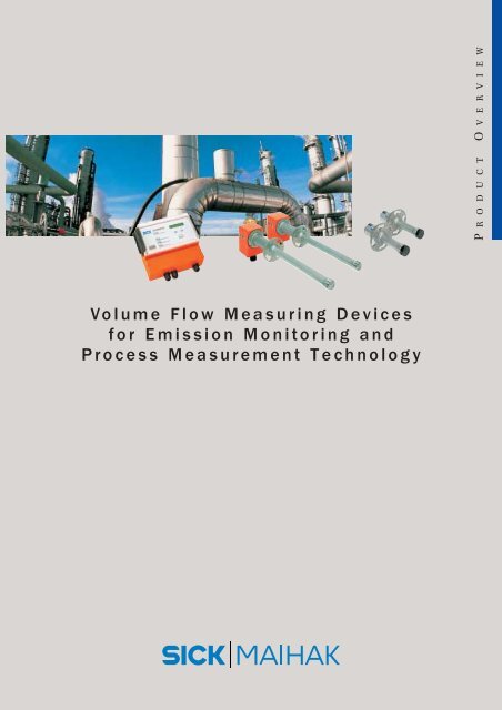
Volume Flow Measuring Devices for Emission Monitoring and ...
Volume Flow Measuring Devices for Emission Monitoring and ...
Volume Flow Measuring Devices for Emission Monitoring and ...

Create successful ePaper yourself
Turn your PDF publications into a flip-book with our unique Google optimized e-Paper software.
<strong>Volume</strong> <strong>Flow</strong> <strong>Measuring</strong> <strong>Devices</strong><br />
<strong>for</strong> <strong>Emission</strong> <strong>Monitoring</strong> <strong>and</strong><br />
Process Measurement Technology<br />
P R O D U C T O V E R V I E W
Ultrasonic measurement technology from S: FLOWSIC series<br />
Notably More Applications.<br />
The FLOWSIC series from<br />
S provides solutions <strong>for</strong> a<br />
wide variety of measuring<br />
tasks – from calculating volume<br />
flows in process <strong>and</strong> environmental<br />
monitoring applications<br />
to recording wind velocities<br />
in road tunnels. Thanks to<br />
its modular design, the<br />
FLOWSIC series can be used<br />
in many applications.<br />
The FLOWSIC devices per<strong>for</strong>m<br />
no-contact measurements<br />
of gas velocities, gas<br />
temperatures, <strong>and</strong> volumetric<br />
flow rates directly in ducts,<br />
pipelines, <strong>and</strong> stacks.<br />
<strong>Emission</strong>s monitoring<br />
Continuous, no-contact, <strong>and</strong><br />
direct – the FLOWSIC devices<br />
supply accurate <strong>and</strong> reliable<br />
measurements of the volume<br />
flows <strong>and</strong> gas velocities in<br />
flue-gas, exhaust-gas ducts<br />
or chimneys. They fulfill the<br />
requirements of the German<br />
Clean Air Act <strong>and</strong> the Pollution<br />
Control Act (13th, 17th Impl.<br />
Ordinances), <strong>and</strong> con<strong>for</strong>m<br />
with U.S. EPA specifications.<br />
Process monitoring<br />
The reliability, precision, <strong>and</strong><br />
short response times of the<br />
FLOWSIC series significantly<br />
enhance the efficiency of<br />
open <strong>and</strong> closed-loop control<br />
circuits. Instantaneous measurements<br />
reflect the current<br />
process status – even under<br />
extreme conditions, such as<br />
high temperatures or pressures.<br />
Tunnel sensors<br />
Measurements of the wind<br />
velocity <strong>and</strong> wind direction in<br />
tunnel <strong>and</strong> exhaust ducts can<br />
be used to optimize the operation<br />
of fan controllers.<br />
Operating principle:<br />
Ultrasonic transducers are<br />
mounted on both sides of the<br />
gas duct at a certain angle to<br />
the direction of flow. These<br />
transducers alternately transmit<br />
<strong>and</strong> receive sound pulses<br />
with <strong>and</strong> against the flow direction.<br />
FLOWSIC measures<br />
the propagation time delay of<br />
the pulses <strong>and</strong> uses this to<br />
calculate the velocity of the<br />
gas <strong>and</strong> determine the volume<br />
flow during operation.<br />
<strong>Measuring</strong> Technique<br />
The tried-<strong>and</strong>-tested in-situ<br />
technology from S also<br />
<strong>for</strong>ms the basis of the ultrasonic<br />
measuring principle.<br />
The following versions are<br />
available:<br />
Cross-stack, that means<br />
the measurement across<br />
the entire duct diameter<br />
Probe version <strong>for</strong> installation<br />
on one side of the<br />
measuring location.<br />
Features<br />
Modular concept: modules<br />
specifically tailored <strong>for</strong> the<br />
measuring task <strong>and</strong> ambient<br />
conditions<br />
Easy to install <strong>and</strong> highly reliable<br />
with low maintenance<br />
requirements<br />
Integrated measurement of<br />
the gas velocity across the<br />
duct diameter, independent<br />
of the pressure, temperature,<br />
<strong>and</strong> gas composition<br />
The gas flow is not disrupted,<br />
as no pressure-reducing<br />
components are installed in<br />
the duct.<br />
Benefits <strong>for</strong> you<br />
Reliable, accurate, easy to<br />
plan <strong>and</strong> install <strong>and</strong> commission.<br />
Extremely low maintenance<br />
requirements during<br />
operation.<br />
2
<strong>Measuring</strong> technology <strong>for</strong> all industries:<br />
Power supply<br />
Power plants<br />
Natural gas industry<br />
Processing industry<br />
Cement industry<br />
Iron <strong>and</strong> steel manufacturing<br />
Tunnel sensors<br />
Road tunnels<br />
Exhaust ducts<br />
Waste-disposal industry<br />
Refuse incineration plants<br />
Residual waste incinerators<br />
Other areas of application<br />
Air-conditioning systems<br />
Ventilation <strong>and</strong> heating<br />
systems<br />
Combustion plants<br />
Chemical engineering plants<br />
Chemicals industry<br />
Chemical plants<br />
Pharmaceuticals industry<br />
Food industry<br />
Plastics industry<br />
Glass manufacturing<br />
industry<br />
Process Control <strong>Emission</strong> <strong>Monitoring</strong><br />
3
The FLOWSIC series at a glance:<br />
Modular System – For All Your Measurement<br />
Model<br />
Unpurged Unpurged Unpurged Unpurged<br />
High power Medium pow. Small size Medium pow.<br />
Digital Digital Digital Analog<br />
Purged Purged Purged<br />
High power Medium pow. Medium pow<br />
Digital Digital Analog<br />
Application data<br />
Application<br />
<strong>Measuring</strong> path [m]<br />
Inner channel diameter [m] 1)<br />
Gas temperature max.<br />
Inner channel pressure max.<br />
Dust concentration (load) max.<br />
Ambient temperature<br />
Distance evaluation unit –<br />
transmitter/receiver unit<br />
Compliance<br />
FLOWSIC 100<br />
UHD UMD USD PR UMA<br />
<strong>Emission</strong> monitoring (CEM)<br />
Process measurement<br />
2.0 …15.0 0.2…4.0 0.3 m 0.2…2.0<br />
1.4 …13.0 0.14…3.4 > 0.35 0.14…1.7<br />
220 °C 2) 200 °C 220 °C 2)<br />
± 0.1 bar<br />
10 g/m 3 5) 1 g/m 3 s.s.<br />
–20 °C +55 °C<br />
1000 m 6) 5 m<br />
—<br />
FLOWSIC 100<br />
PHD PMD PMA<br />
<strong>Emission</strong> monitoring (CEM)<br />
Process measurement<br />
1.0 …10.0 0.5…3.0 0.5…2.0<br />
0.7 …8.7 0.35…2.5 0.35…1.7<br />
450 °C 300 °C<br />
,<br />
0.03 bar 3) , 0.1 bar 4)<br />
100 g/m 3 s.s. 5) 1 g/m 3 s.s.<br />
–20 °C +55 °C<br />
1000 m 6) 5 m<br />
13. BImSchV 17. BImSchV Part 60/75<br />
13. BImSchV 17. BImSchV Part 60/75<br />
4<br />
Device Data<br />
UHD UMD USD PR UMA PHD PMD PMA<br />
Measured quantity<br />
Gas velocity, volume flow s.s./o.s., gas temperature<br />
gas velocity, volume flow s.s./o.s., gas temperature<br />
<strong>Measuring</strong> range<br />
v: ± 40 m/s; freely selectable v: ± 40 m/s; freely selectable<br />
Accuracy emission measur. 8) ± 0.1 m/s ± 0.1 m/s<br />
Reproducibility process control ±1% <strong>for</strong> v> 2 m/s; ±0.02 m/s <strong>for</strong> v< 2 m/s ±1% <strong>for</strong> v> 2 m/s; ±0.02 m/s <strong>for</strong> v< 2 m/s<br />
Signals<br />
1 analog output: 0/2/4…20 mA; 750 Ω load 1 analog output: 0/2/4…20 mA; 750 Ω load<br />
4 relay outputs f. status signals: 48 V/1 A (el. isolated) 4 relay outputs f. status signals: 48 V/1 A (el. isolated)<br />
Interfaces<br />
RS 232 RS 232<br />
Response time (T 90<br />
)<br />
1…300 s; freely selectable 1…300 s; freely selectable<br />
Mounting angle<br />
45°…60° 45° 45°…60° 45°…60°<br />
Options<br />
2 analog modules max. 0…20 mA, 1 pulse output 1 analog module 2 analog modules, 1 pulse output 1 analog module<br />
1 interface module RS 232/422/485 1 pulse output 1 interface mod. RS 232/422/485 1 pulse output<br />
Purge-air supply<br />
— Purge-air unit <strong>for</strong> inner ch. pressure: –0.1…+0.1 bar<br />
Power supply<br />
90…140 V AC/180…240 V AC; 50/60 Hz; ca. 20 W 90…140 V AC/180…240 V AC; 50/60 Hz; ca. 20 W<br />
Protection class<br />
IP 65 IP 65<br />
1)<br />
Depending on mounting angle 2) Depending on material<br />
3)<br />
With st<strong>and</strong>ard purge-air unit 2BH13<br />
4)<br />
With purge-air unit 2BH14<br />
5)<br />
At measuring path up to 2 m<br />
6)<br />
) Cab<br />
s.s. … st<strong>and</strong>ard state; o.s. … operation state
Needs<br />
Unpurged Unpurged Unpurged<br />
Medium pow. Medium pow. Medium pow.<br />
Analog Digital Digital<br />
FLOWSIC 100<br />
UMA PN16 UMD PN16 UMD EX<br />
Measurement at high pressure<br />
Process meas. Ex area I<br />
0.2…2.0<br />
FLOWSIC 150 Car flow<br />
<strong>Flow</strong> measurement engine test beds<br />
Nominal length measuring channel:<br />
DN65; others on request<br />
FLOWSIC 200<br />
Air velocity in road tunnels<br />
5 …40 7)<br />
0.14…1.7<br />
0.14…1.7<br />
3.6 …34 7)<br />
200 °C 180 °C<br />
16 bar<br />
1 g/m 3 s.s.<br />
250 °C<br />
—<br />
—<br />
50 °C<br />
—<br />
—<br />
–20 °C +55 °C<br />
5 m 1000 m 5)<br />
–20 °C +55 °C<br />
Compact measuring system<br />
–20 °C …+50 °C<br />
1000 m 5)<br />
EEx me II, C T4<br />
UMA PN16 UMD PN16 UMD EX<br />
gas velocity, volume flow s.s./o.s., gas temperature<br />
± 40 m/s; freely selectable<br />
±0.1 m/s<br />
±1% <strong>for</strong> v> 2 m/s; ±0.02 m/s <strong>for</strong> v< 2 m/s<br />
1 analog output: 0/2/4…20 mA; 750 Ω load<br />
4 relay outputs <strong>for</strong> status signals: 48 V/1 A (el. isolated)<br />
RS 232; option: interface module RS 232/422/485<br />
1…300 s; freely selectable<br />
45°…60°<br />
1 analog module 2 analog modules max. 0…20 mA<br />
1 pulse output 1 interface module RS 232/422/485<br />
—<br />
90…140 V AC/180…240 V AC; 50/60 Hz; ca. 20 W<br />
IP 65<br />
FLOWSIC 150 Car flow FLOWSIC 200<br />
volume flow, temperature, pressure<br />
Air velocity, direction, temperature<br />
± 150 l/s ± 20 m/s<br />
500 m use data repeater option<br />
7)<br />
FLOWSIC 200-M (5…25 m)<br />
7)<br />
FLOWSIC 200-H (5…40 m)<br />
5
FLOWSIC 100 UHD/UMD<br />
Unpurged versions – digital<br />
Design of the FLOWSIC 100 UHD/UMD<br />
FLOWSIC 100<br />
UHD UMD USD PR UMA<br />
Transmitter/<br />
receiver<br />
unit<br />
Transmitter/receiver unit<br />
Connection<br />
cable<br />
Evaluation unit<br />
FLA 100-D/A<br />
Status/control<br />
signals<br />
The measuring device comprises the following components:<br />
2 Transmitter/receiver units (TR units) FLSE 100<br />
<strong>for</strong> transmitting <strong>and</strong> receiving ultrasonic pulses<br />
Flange with tube<br />
<strong>for</strong> mounting the TR units on the measuring duct<br />
FLA 100-D Evaluation Unit (digital version) or FLA 100-A<br />
(analog version) <strong>for</strong> signal processing, controlling the system<br />
functions, <strong>and</strong> signal input/output<br />
Connection cable<br />
<strong>for</strong> transferring the analog <strong>and</strong> digital signals between the TR<br />
unit <strong>and</strong> Evaluation Unit<br />
Special Features of the UHD/UMD<br />
Digital signal transmission between TR unit <strong>and</strong> Evaluation Unit; FLA can be used up to 1000 m from the measuring location<br />
Temperature sensor <strong>for</strong> monitoring the transducer temperature<br />
Dimensions transmitter/receiver unit FLOWSIC 100 UHD <strong>and</strong> UMD<br />
FLOWSIC 100 UHD<br />
Tr unit<br />
Connection<br />
A<br />
Duct probe Transducer A — A<br />
FLOWSIC 100 UMD<br />
Tr unit<br />
Connection<br />
A<br />
Duct probe Transducer A — A<br />
120<br />
∅35<br />
120<br />
A<br />
80 132<br />
350, 550, 750<br />
PVDF 350 only<br />
∅100<br />
∅125<br />
A<br />
80 132<br />
200, 350, 550<br />
PVDF 350 only<br />
∅75<br />
∅100
FLOWSIC 100 USD PR (Probe)<br />
Probe version<br />
FLOWSIC 100 UMA<br />
Unpurged– analog<br />
Transmitter/receiver unit<br />
Connection<br />
cable<br />
Evaluation unit<br />
FLA 100-D<br />
Status/<br />
control singals<br />
Tr unit<br />
Transmitter/receiver unit<br />
Connection<br />
cable<br />
Evaluation unit<br />
FLA 100-A<br />
Status/<br />
control singals<br />
FLOWSIC 100<br />
UHD UMD USD PR UMA<br />
Special Features<br />
Compact design <strong>for</strong> easy installation on one side of the duct<br />
Digital signal transmission between TR unit <strong>and</strong> Evaluation Unit<br />
Temperature sensor <strong>for</strong> monitoring the transducer temperature<br />
Special Features<br />
Analog signal transmission between TR unit <strong>and</strong> Evaluation Unit<br />
Distance from measuring location = 5 m<br />
No electronic probe components required<br />
Dimensions transmitter/receiver unit FLOWSIC 100 USD PR <strong>and</strong> UMA<br />
FLOWSIC 100 USD PR (measuring probe)<br />
Tr unit<br />
Connection<br />
Duct probe with transducer<br />
A — A<br />
A<br />
FLOWSIC 100 UMA<br />
Connection<br />
Duct probe<br />
Transducer<br />
∅35<br />
120<br />
A<br />
∅60,3<br />
300<br />
∅100<br />
80 132<br />
350, 550, 750<br />
506,4<br />
∅125<br />
∅35<br />
∅75<br />
132 125, 200, 350<br />
∅100
FLOWSIC 100 PHD, PMD <strong>and</strong> PMA<br />
Purged versions<br />
FLOWSIC 100<br />
PHD PMD PMA<br />
Tr unit<br />
Puge-air<br />
unit<br />
Tr unit<br />
Connection<br />
cable<br />
Special Features of the PHD/PMD<br />
Evaluation unit<br />
FLA 100-D/A<br />
Suitable <strong>for</strong> use with high gas temperatures or gases with “sticky” dusts<br />
Digital signal transmission between TR unit <strong>and</strong> Evaluation Unit<br />
FLA 100-D<br />
Temperature sensor <strong>for</strong> monitoring the transducer temperature<br />
Design of the FLOWSIC 100 PHD/PMD/PMA<br />
The measuring device comprises the following components:<br />
2 Transmitter/receiver units (TR units) FLSE 100<br />
<strong>for</strong> transmitting <strong>and</strong> receiving ultrasonic pulses<br />
Flange with tube<br />
<strong>for</strong> mounting the TR units on the measuring duct<br />
FLA 100-D Evaluation Unit (digital version) or FLA 100-A<br />
(analog version) <strong>for</strong> signal processing, controlling the system<br />
functions, <strong>and</strong> signal input/output<br />
Connection cable<br />
<strong>for</strong> transferring the analog <strong>and</strong> digital signals between the TR<br />
unit <strong>and</strong> Evaluation Unit<br />
Purge-air unit<br />
<strong>for</strong> cooling <strong>and</strong> protecting the ultrasonic transducers from dirt<br />
Special Features of the PMA<br />
Analog signal transmission between TR unit <strong>and</strong> Evaluation Unit<br />
FLA 100-A; distance from measuring location = 5 m<br />
No electronic probe components required<br />
Dimensions transmitter/receiver units FLOWSIC 100 PMD/PHD <strong>and</strong> PMA<br />
FLOWSIC 100 PHD/PMD<br />
Tr unit<br />
Purge-air inlet<br />
Duct probe<br />
Transducer<br />
A — A<br />
A<br />
FLOWSIC 100 PMA<br />
Cable connection<br />
Duct probe<br />
Transducer<br />
90<br />
∅60,3<br />
120<br />
A<br />
∅40<br />
80 132<br />
350, 550, 750<br />
PVDF 350 only<br />
∅100<br />
∅125<br />
292, 442<br />
200, 350<br />
∅40<br />
∅125<br />
8
FLOWSIC UMA PN16/UMD PN16<br />
For High Pressure<br />
FLOWSIC UMD EX (explosion protected type)<br />
For Hazardous Areas<br />
Tr unit<br />
Ex zone I; EEx me II C T4<br />
Tr unit<br />
Evaluation unit<br />
FLA 100-D<br />
Tr unit<br />
Tr unit<br />
Evaluation unit<br />
FLA 100-D<br />
Status/<br />
control signals<br />
Connection<br />
cable<br />
Special Features of the UMD PN16/UMA PN16<br />
Suitable <strong>for</strong> use in pressures up to 16 bar<br />
Digital signal transmission bet. TR unit (UMD PN16) <strong>and</strong> FLA 100-D<br />
Analog signal transmission bet. TR unit (UMA PN16) <strong>and</strong> FLA 100-A<br />
Special Features of the FLOWSIC 100 UMD EX<br />
Suitable <strong>for</strong> use in pressures up to 16 bar <strong>and</strong> in hazardous areas<br />
Digital signal transmission between TR unit <strong>and</strong> Evaluation Unit<br />
Temperature sensor <strong>for</strong> monitoring the transducer temperature<br />
FLOWSIC 100<br />
UMA PN16 UMD PN16 UMD Ex<br />
Dimensions transmitter/receiver units FLOWSIC 100 UMA PN16, UMD PN16, UMD EX<br />
FLOWSIC 100 UMD EX<br />
FLOWSIC 100 UMA PN16<br />
Connection box<br />
Connection<br />
Duct probe with<br />
flange C50 PN16<br />
DIN 2527 1.4571<br />
Transducer<br />
∅35<br />
120<br />
75<br />
∅125<br />
55<br />
98<br />
260<br />
∅164<br />
FLOWSIC 100 UMD PN16<br />
Connection A<br />
Duct probe with<br />
flange C50 PN16<br />
DIN 2527 1.4571<br />
Transducer<br />
A — A<br />
∅35<br />
A<br />
∅35<br />
80<br />
132 260<br />
∅125<br />
∅164
FLOWSIC 150 Car <strong>Flow</strong> FLOWSIC 200<br />
Engine test beds Tunnel sensors<br />
Control cabinet with<br />
evaluation electronics<br />
Transmitter/receiver units<br />
Evaluation unit<br />
FLA 100-D<br />
<strong>Measuring</strong><br />
cell<br />
Connection<br />
(quick-release)<br />
Connection<br />
cable<br />
Status/<br />
control signals<br />
Special Features of the FLOWSIC 150 Car <strong>Flow</strong><br />
Compact measuring system <strong>for</strong> mobile applications<br />
For chassis dynamometers, as used in the automotive industry<br />
Temperature <strong>and</strong> pressure measurements <strong>for</strong> normalization<br />
Special Features of the FLOWSIC 200<br />
No purge air required due to specially designed transducers<br />
Digital signal transmission between TR unit <strong>and</strong> Evaluation Unit so that<br />
the FLA can be used up to 1000 m from the measuring location<br />
Temperature sensor <strong>for</strong> monitoring the transducer temperature<br />
FLOWSIC 200 FLOWSIC 150<br />
Tunnel Car <strong>Flow</strong><br />
Dimensions FLOWSIC 150 Car <strong>Flow</strong><br />
700<br />
600<br />
490<br />
380<br />
Dimensions FLOWSIC 200<br />
Tranmiter/receiver unit<br />
80 45<br />
120<br />
∅34 40<br />
616<br />
300<br />
>150<br />
104<br />
10
Evaluation unit of the FLOWSIC 100 series<br />
User Interface<br />
184<br />
Status indicators<br />
FLOWSIC<br />
Status<br />
Service<br />
Dimensions Evaluation unit FLA 100<br />
10<br />
106<br />
59<br />
29<br />
124<br />
Purge-air<br />
U Unpurged (without purge-air)<br />
P Purged (with purge-air)<br />
Transducer power<br />
S Small power<br />
M Medium power<br />
H High power<br />
Signal transmission<br />
D Digital (RS 485)<br />
A Analog (coax cable)<br />
Identification<br />
_ _ No specific criteria<br />
EX Protected <strong>for</strong> use in hazardous zones<br />
PN16 High pressure (pressure stage PN16)<br />
PR Probe version<br />
Display <strong>for</strong>:<br />
Gas velocity<br />
volumene flow i.B. or i.N.<br />
Gas temperature<br />
Status messages<br />
Control keys<br />
Service<br />
interface<br />
212<br />
Nominal length probe<br />
12 125 mm, 20 200 mm, 35 350 mm, 55 550 mm, 75 750 mm<br />
Probe material<br />
SS Stainless steel<br />
PV PVDF<br />
TI Titanium<br />
Transducer material<br />
AL Aluminium<br />
TI Titanium<br />
FLA 100 Evaluation Unit<br />
The Evaluation Unit is used to control the system<br />
functions, process the recorded measured data<br />
from the transmitter/receiver units, <strong>and</strong> input/<br />
output the signals <strong>and</strong> data. Two control keys<br />
are provided <strong>for</strong> selecting the measured variable,<br />
activating maintenance mode, <strong>and</strong> triggering<br />
a check cycle. Depending on the FLOWSIC<br />
module, the FLA 100 versions are available:<br />
FLA 100-D with digital signal transmission to<br />
the TR units<br />
FLA 100-A with analog signal transmission to<br />
the TR units.<br />
Features FLA 100-D FLA 100-A<br />
Interfaces RS 232 (parameters) RS 232 (Para.)<br />
RS 485 (tr unit)<br />
RS 422 (host)<br />
Outputs 1 analog output:<br />
0/2/4…20 mA; max 750 Ω load<br />
4 relay output: 48 V, 1 A (pot.-frei)<br />
Cable separate cable 5 m (scope of<br />
5, 10, 50 m delivery)<br />
Options 2 analog module 1 analog mod.<br />
1 analog/1 interface<br />
1 pulse output 1) 1 pulse output 1)<br />
1)<br />
200 Hz max./2.5 s; 40 V DC, 0.5 A<br />
Configuration key <strong>for</strong> TR units<br />
FLOWSIC 100 U M D __ 20 SS AL<br />
U<br />
M<br />
D<br />
__<br />
20<br />
SS<br />
AL<br />
FLOWSIC-Serie<br />
FLA 100 Konfig.-Schlüssel
Interested Copy, Fill In, <strong>and</strong> Fax Back<br />
Fax +49 7641 469 1149<br />
Company<br />
F a x R e p l y<br />
Name<br />
Position/<br />
Department<br />
Address<br />
Post code/<br />
Town<br />
Phone/Fax<br />
Industry/Field<br />
of application<br />
Yes, I would like to know<br />
more about:<br />
In-process gas analysis<br />
I am intersted in a detailed consultation<br />
with one of your project consultants.<br />
Please arrange an appointment <strong>for</strong> me.<br />
Flue gas monitoring<br />
<strong>Emission</strong> monitoring<br />
Dust measurement technology<br />
<strong>Volume</strong> flow measurement<br />
Data acquisition <strong>and</strong><br />
evaluation systems<br />
Water analysis<br />
Liquid analysis<br />
Level measurement technology<br />
SICK <strong>and</strong> MAIHAK – the new leading developer of analysis<br />
<strong>and</strong> process measuring technology. SICK also provides<br />
innovative factory automation solutions. As a leading<br />
provider of sensor systems <strong>for</strong> automation technology,<br />
safety systems, process analysis, <strong>and</strong> auto ident systems,<br />
SICK has become a global partner in all areas of industry.<br />
A network of subsidiaries, sales <strong>and</strong> service centers<br />
ensures close contact with customers all over the world.<br />
Tunnel sensors<br />
Special measuring technology<br />
w w w . s i c k . d e<br />
SICK Analysis <strong>and</strong><br />
Process Measurement<br />
with the following locations:<br />
SICK AG<br />
Nimburger Str. 11<br />
79276 Reute<br />
Germany<br />
Tel. +49 76 41/469-0<br />
Fax +49 76 41/469-11 49<br />
SICK Engineering GmbH<br />
Bergener Ring 43<br />
01458 Ottendorf-Okrilla<br />
Germany<br />
Tel. +49 3 52 05/5 24-10<br />
Fax +49 3 52 05/5 24-50<br />
SICK UPA GmbH<br />
Dr.-Zimmermann-Str. 18<br />
88709 Meersburg<br />
Germany<br />
Tel. +49 75 32/8 01-0<br />
Fax +49 75 32/8 01-104<br />
Maihak AG<br />
Poppenbütteler Bogen 9B<br />
22399 Hamburg<br />
Germany<br />
Tel. +49 40/2 78 94- 0<br />
Fax +49 40/2 78 94-242<br />
8009 584/09-01 . GB3/SM . Printed in Germany . Subject to change without prior notice<br />
SICK AG • Analysis <strong>and</strong> Process Measurement • Nimburger Str. 11 • 79276 Reute, Germany • Tel. +49 76 41 4 69-0 • Fax +49 76 41 4 69-11 49<br />
www.sick.de