FLOWSIC 200 Measuring Flow speed Why choose the FLOWSIC 200?
FLOWSIC 200 Measuring Flow speed Why choose the FLOWSIC 200?
FLOWSIC 200 Measuring Flow speed Why choose the FLOWSIC 200?

You also want an ePaper? Increase the reach of your titles
YUMPU automatically turns print PDFs into web optimized ePapers that Google loves.
<strong>FLOWSIC</strong>2<br />
00<br />
P R O D U C T I N FORMAT I O N<br />
<strong>FLOWSIC</strong> <strong>200</strong><br />
<strong>Measuring</strong> <strong>Flow</strong> <strong>speed</strong><br />
A real titan – outstanding amongst<br />
longterm tunnel monitoring devices.<br />
In over <strong>200</strong> tunnels worldwide.<br />
<strong>Why</strong> <strong>choose</strong> <strong>the</strong> <strong>FLOWSIC</strong> <strong>200</strong><br />
■ Minimizing your operating expenses by service intervals of up to 5 years 1<br />
■ Capable of covering very long measured section of up to 40 meters<br />
■ Made from extremely rugged hardware – titan, stainless steel and die cast<br />
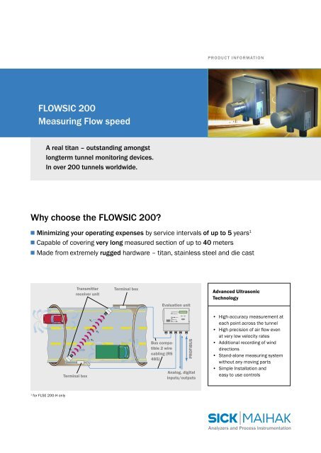
Transmitter<br />
receiver unit<br />
Terminal box<br />
Evaluation unit<br />
Advanced Ultrasonic<br />
Technology<br />
v 3<br />
v 4<br />
Terminal box<br />
v 1<br />
v 2<br />
Bus compatible<br />
2 wire<br />
cabling (RS<br />
485)<br />
PROFIBUS<br />
Analog, digital<br />
inputs/outputs<br />
• High-accuracy measurement at<br />
each point across <strong>the</strong> tunnel<br />
• High precision of air flow even<br />
at very low velocity rates<br />
• Additional recording of wind<br />
directions<br />
• Stand-alone measuring system<br />
without any moving parts<br />
• Simple Installation and<br />
easy to use controls<br />
1<br />
for FLSE <strong>200</strong>-H only<br />
Analyzers and Process Instrumentation
8 007 537/06-<strong>200</strong>5/BW • Printed in Germany (07-<strong>200</strong>5) • Subject to change without prior notice<br />
Evaluation Unit<br />
Ultrasonic Measurement Principle<br />
Ultrasonic transducers which act<br />
alternately as transmitter and<br />
receiver are installed on ei<strong>the</strong>r side<br />
of <strong>the</strong> tunnel at an angle of 45° to<br />
60° to <strong>the</strong> tunnel axis. The transit<br />
time of each sonic pulse depends on<br />
wind <strong>speed</strong> and direction, with <strong>the</strong><br />
transit time being shorter at forward<br />
and longer at reverse direction. From<br />
<strong>the</strong> difference in transit time air<br />
velocity can be calculated irrespective<br />
of pressure and temperature<br />
conditions. Measurement value<br />
processing safeguards high accuracy<br />
and noise resistance for <strong>the</strong> measured<br />
values of <strong>the</strong> <strong>FLOWSIC</strong> <strong>200</strong>.<br />
Commisioning and Maintenance<br />
Parameters are set with <strong>the</strong> help of<br />
our easy to use MEPAFLOW <strong>200</strong>, a<br />
window compatible software program.<br />
The evaluation unit and <strong>the</strong> computer<br />
are connected via a RS 232 interface.<br />
The setting of parameters, regarding<br />
i.e. measuring distance, range and<br />
response time are, thanks to MEPA-<br />
FLOW <strong>200</strong> a simple task. A manual<br />
zero-point adjustment is no longer<br />
necessary as this is carried out automatically<br />
by <strong>the</strong> measurement device.<br />
During every day running operation<br />
MEPAFLOW offers an extensive diagnosis<br />
routine. Maintenance of <strong>the</strong><br />
<strong>FLOWSIC</strong> <strong>200</strong> consits of cleaning <strong>the</strong><br />
transceiver unit. The maintenance<br />
intervals of ½ to 1 year up to 5 years<br />
are based on individual installation<br />
conditions and <strong>the</strong> device model used.<br />
Technical Data <strong>FLOWSIC</strong> <strong>200</strong><br />
Type of models:<br />
Transceiver unit<br />
Evaluation Unit<br />
Measurement Data<br />
Measur. component<br />
<strong>Measuring</strong> Principle<br />
<strong>Measuring</strong> range<br />
Accuracy<br />
<strong>Measuring</strong> distance<br />
Response time<br />
Selection of transceiver units<br />
• FLSE <strong>200</strong>-M, Aluminium cast housing (alumin. transducer)<br />
• FLSE <strong>200</strong>-M SS, Stainl. Steel housing (alumin. transducer)<br />
• FLSE <strong>200</strong>-H, Stainless Steel housing (titanium transducer)<br />
<strong>Measuring</strong> value processing/output, monitor function;<br />
cable length to TR unit: 500 m max. (with optional data<br />
repeater 1000 m max.); larger distances on request<br />
Velocity of air flows<br />
Measurement of difference in ultrasonic transit time<br />
–20 m/s (65 ft/sec) ... + 20 m/s (65 ft/sec); cont. variable<br />
± 0.1 m/s (0.3 ft/sec); depending on calibration, installation,<br />
flow profile, temp. and measuring distance<br />
5 … 25 m (16 … 82 ft) with FLSE <strong>200</strong>-M and -M SS<br />
5 … 40 m (16 … 130 ft) with FLSE-H; larger on request<br />
1 … 300 s (sec); freely selectable<br />
Ambient Conditions<br />
Ambient temperature –20…+50 °C (–4 … 120 °F)<br />
Device Data<br />
Maintenance intervals ½… 1 year: FLSE <strong>200</strong>-M<br />
1 … 5 years: FLSE <strong>200</strong>-H depend. on application cond.<br />
Point of Installation<br />
• Height above road 4.2 m (14 ft) typical<br />
• Angle to tunnel axis 45° … 60°<br />
Displays<br />
• <strong>Measuring</strong> values<br />
• Status<br />
Power supply<br />
Dimensions<br />
(L x W x D)<br />
FLSE <strong>200</strong>-M,<br />
Aluminium Cast Housing<br />
c FLSE <strong>200</strong>-H,<br />
stainl. steel housing (titan transducer)<br />
c FLSE <strong>200</strong>-M SS;<br />
stainless steel housing<br />
LC-Display with 2 rows<br />
LEDs (operation, faults, maintenance, cycles)<br />
90 … 140/190 … 260 V AC; 50/60 Hz;<br />
power consumption: approx. 20 W max.<br />
FLSE <strong>200</strong>-M: 80 x 80 x 120 mm 3 (260 x 260 x 393 ft 3 )<br />
FLSE <strong>200</strong>-M SS/H: 80 x 150 x 150 mm 3 (260 x 492 x 492 ft 3 )<br />
FLA <strong>200</strong>: 240 x <strong>200</strong> x 120 mm 3 (787 x 565 x 394 ft 3 )<br />
Weight FLSE <strong>200</strong>-M: approx. 1 kg (2.2 lb)<br />
FLSE <strong>200</strong>-M SS/H: approx. 2 kg (4.4 lb)<br />
FLA <strong>200</strong>: approx. 1.5 kg (3.3 lb)<br />
Protection class IP 65/NEMA 4X<br />
Connection/Interface via evaluation unit (customer-provided)<br />
Signals<br />
1 analog output: 0…20 mA, 750 Ω max. load<br />
optional: max. 2 additional analog modules (inputs/outputs)<br />
4 relays: 48 V AC, 1 A; electrically isolated<br />
Interface<br />
RS 232 for service purposes;<br />
optional: PROFIBUS, RS 422 for data transfer<br />
SICK MAIHAK GmbH | Analyzers and Process Instrumentation<br />
Nimburger Str. 11 | 79276 Reute | Germany | www.sick-maihak.com<br />
Fon +49 7641 4 69-0 | Fax 0 76 41 4 69-11 49 | info.sick-maihak@sick.de<br />
Analyzers and Process Instrumentation