PKG-EML30-EDB30-CBLS Spec Sheet.pdf - Anaheim Automation
PKG-EML30-EDB30-CBLS Spec Sheet.pdf - Anaheim Automation
PKG-EML30-EDB30-CBLS Spec Sheet.pdf - Anaheim Automation

Create successful ePaper yourself
Turn your PDF publications into a flip-book with our unique Google optimized e-Paper software.
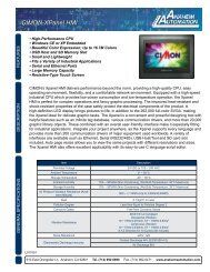
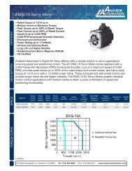
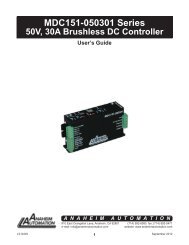
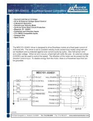
<strong>PKG</strong>-<strong>EML30</strong>-<strong>EDB30</strong>-<strong>CBLS</strong><br />
System Diagram and <strong>Spec</strong>ifications<br />
Included Components:<br />
EML-30APA22 AC Servo Motor<br />
EDB-30AMA<br />
Servo Driver<br />
BDM-GA14-05<br />
Power Cable<br />
BMP-GA24-05 Encoder Cable<br />
EDB-BSC-CC24A Comm Cable<br />
L010911<br />
A: Continuous Working Area<br />
B: Repeatedly Wokring Area<br />
910 East Orangefair Ln. <strong>Anaheim</strong>, CA 92801 Tel. (714) 992-6990 Fax. (714) 992-0471 www.anaheimautomation.com
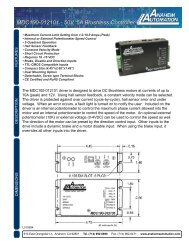
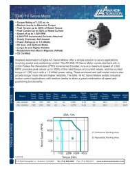
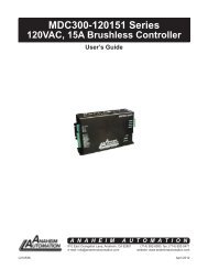
EML-30APA22 180mm AC Servo Motor<br />
DESCRIPTION<br />
• Rated Torque fof 4,064 oz.-in.<br />
• Medium Inertia to Maximize Torque<br />
• Peak Torque up to 300% of Rated Torque<br />
• Peak Current up to 300% of Rated Current<br />
• Speed of up to 3,000 RPM<br />
• 2,500 PPR Incremental Encoder Attached<br />
• Enclosed and Self-Cooled<br />
• Power Ratings up to 3.0 to 5.0 kWatts<br />
• Oil Seal and Optional Brake<br />
• Long Life and Highly Reliable<br />
• Neodymium-Iron-Boron Magnets (NdFeB)<br />
• CE Certified<br />
DESCRIPTION<br />
<strong>Anaheim</strong> <strong>Automation</strong>’s AC servo motor offers a simple solution to servo applications. The AC<br />
Servo motor is equipped with a 2,500 counts-per-revolution encoder. The AC Servo motor<br />
enables industrial motion control applications with medium inertia to attain a great combination<br />
of speed and positioning capability. The EML AC Servo motor offers a cost-effective solution to<br />
many velocity and position controlled applications.<br />
SPECIFICATIONS<br />
Model #<br />
Rated<br />
Torque<br />
(oz-in)<br />
Power Requirement<br />
220VAC<br />
Insulation Class: F<br />
Ambient Temp: 0° to 40° C<br />
Running Temp: -25° to<br />
40° C<br />
Rated<br />
Power<br />
(Watts)<br />
Max<br />
Speed<br />
(rpm)<br />
Rated<br />
Speed<br />
(rpm)<br />
Rated<br />
Current<br />
(A rms)<br />
Vibration: 49m/s 2<br />
Ambient Humidity: 20 to 80% RH<br />
IP Rating: IP65<br />
Inertia<br />
(oz-insec<br />
2 )<br />
Electric<br />
Time<br />
Constant<br />
T E<br />
(ms)<br />
Running Humidity: Not more than 90%, under 25°C<br />
Mechanical<br />
Time<br />
Constant<br />
T E<br />
(ms)<br />
Back EMF<br />
Voltage K E<br />
(V/krpm)<br />
Torque<br />
Constant<br />
K T<br />
(oz-in/A)<br />
Running Air Pressure: 86-106 kPa<br />
Resistance<br />
(ohms)<br />
EML-30APA22 4064 3000 1500 1000 18.0 1.1017 18.87 1.21 116 270.0 0.3<br />
Insulation Voltage Endurance: AC 1800V, 50Hz,<br />
1min<br />
Insulation Impedance: Not Less than 50M Under<br />
Normal Conditions<br />
910 East Orangefair Ln. <strong>Anaheim</strong>, CA 92801 Tel. (714) 992-6990 Fax. (714) 992-0471 www.anaheimautomation.com
EDB series AC servo system<br />
User’s Manual V. 2.00<br />
<strong>Anaheim</strong> <strong>Automation</strong> Limited Warranty<br />
This manual does not entitle you to any rights. <strong>Anaheim</strong> <strong>Automation</strong> reserves the right to change<br />
this manual without prior notice. All rights reserved. No part of this publication may be copied or<br />
reproduced without written permission from <strong>Anaheim</strong> <strong>Automation</strong>.<br />
1
General Precautions<br />
■<br />
■<br />
■<br />
■<br />
■<br />
■<br />
■<br />
■<br />
■<br />
Voltage of power supply is 200V<br />
Please connect to 200V voltage electrical source<br />
Don’t connect Servomotor directly to the residential electric network.<br />
Do not connect Servomotor directly to the residential electric network; otherwise, it will be damaged.<br />
Servomotor is not able to work without relevant Servo drive.<br />
Don’t plug or unplug the electric socket when power is ON.<br />
Always turn the power OFF before plug or unplug to the electric socket.<br />
Wait at least five minutes before inspection after turning OFF power<br />
Note that even when the power is turned off, there will still be residual voltage remained in the capacitor. In<br />
order to avoid electrical shock, please make sure the Charge lamp is OFF before inspection.<br />
The installation interval to other equipment is above 10mm.<br />
The installation interval to other equipment should be at least 10mm breadthways and 50mm lengthways.<br />
The Servo drive generates heat, please layout the Installation the Servo drive which is good to radiate heat.<br />
Please install the Servo drive in an environment free from condensation, vibration and shock.<br />
Please take treatment of anti-disturbance and grounding properly.<br />
If there are disturbance in the signal line, vibration or malfunction will likely occur.<br />
Please stick to the following rules strictly:<br />
1. Separate high-voltage cable from low-voltage cable.<br />
2. Make cables as short as possible<br />
3. Apply one phase grounding (ground resistance less than 100Ω) for the installation of Servomotor and<br />
Servo drive.<br />
4. NO power input noise filter between servo drive and servomotor.<br />
Please conduct voltage endurance under following conditions:<br />
5. Voltage: AC 1500Vrms, 1 min<br />
6. Cut the current: 100mA<br />
7. Frequency: 50/60Hz<br />
8. Voltage applied point: L1, L2, L3 pins and FG tie-in (Please fast the connection among terminals).<br />
Creepage prevention instrument: please select quick-response type<br />
For a ground-fault interrupter, always use a quick response type or one designed for PWM inverters. Do not<br />
use a time-delay type.<br />
Don’t perform continuous operation under overhanging load.<br />
Continuous operation cannot be performed by rotating the motor from the load and applying regenerative<br />
braking. Regenerative braking by the Servo drive can be applied only for a short period, such as the motor<br />
deceleration time.<br />
Turning the Power On and Power Off frequently will result in speeding up deterioration of internal elements.<br />
Please control the servo motor with reference signals.<br />
2
Content<br />
Chapter 1 .......................................................................................................................................................................... 6<br />
Checking products and parts names .................................................................................................................................. 6<br />
1. 1 Check products ..................................................................................................................................................... 6<br />
1.1.1 Servo drive ........................................................................................................................... 7<br />
1.2 Product Parts names ..................................................................................................................................... 8<br />
1.2.1 Servo drive ..................................................................................................................................................... 8<br />
Chapter 2 .......................................................................................................................................................................... 9<br />
Installation ........................................................................................................................................................................... 9<br />
2.1 Servodrive ............................................................................................................................................................. 9<br />
2.2.1 Storage ................................................................................................................................. 9<br />
2.2.2 Installation sites .................................................................................................................... 9<br />
2.2.3 Installation orientation ........................................................................................................ 10<br />
2.2.4 Installation method ............................................................................................................. 10<br />
Chapter 3 .......................................................................................................................................................................... 11<br />
Wirings and connections ................................................................................................................................................... 11<br />
3.1 Wirings and connections for main circuit ............................................................................................................ 11<br />
3.1.1 Names and Functions of Main Circuit Terminals ............................................................... 11<br />
3.1.2 Typical main circuit wiring example ................................................................................... 12<br />
3.2 Input and output signal ........................................................................................................................................ 12<br />
3.2 Input and output signal ........................................................................................................................................ 13<br />
3.2.1 Connection of input and output signals ............................................................................................................ 13<br />
3.2.2 Terminal layout of connector 1CN ..................................................................................... 14<br />
3.2.3 I/O signal names and functions ......................................................................................... 15<br />
3.2.4 Interface Circuit .................................................................................................................. 17<br />
3.3 wiring encoders ................................................................................................................................................... 18<br />
3.3.1 Connecting an Encoder (2CN) and Output Signals from the servodrive ........................................................ 18<br />
3.3.2 Encoder Connector (CN2) Terminal Layout ...................................................................... 18<br />
3.4 Wiring servo motor .............................................................................................................................................. 19<br />
3.4.1 Encoder Connector Terminal Layout ............................................................................. 19<br />
3.4.2 Dynamic power Connector Terminal layout ...................................................................... 19<br />
3.5 Typical wiring example ........................................................................................................................................ 20<br />
3.5.1 Position control mode ....................................................................................................................................... 20<br />
3.5.1 Position control mode ....................................................................................................................................... 21<br />
3.5.2 Speed control mode ...................................................................................................... 22<br />
3.5.3 Torque control mode ..................................................................................................... 23<br />
Chapter 4 .......................................................................................................................................................................... 24<br />
Parameter Setting and function description ..................................................................................................................... 24<br />
4.1 Setting Parameters according to mechanical features ....................................................................................... 24<br />
4.1.1 Changing the Direction of Motor Rotation ......................................................................... 24<br />
Select the rotating direction by setting parameters below: ....................................................................................... 24<br />
4.1.2 Setting overtravel limit .................................................................................................. 25<br />
4.1.3 Limiting Torque ............................................................................................................. 26<br />
3
4.2 Setting Parameters According to Host Controller ............................................................................................... 29<br />
4.2.1 Speed Reference ............................................................................................................... 29<br />
4.2.2 Position reference .............................................................................................................. 34<br />
4.2.3 Encoder signal output .................................................................................................... 38<br />
4.2.4 Contact I/O Signals ...................................................................................................... 41<br />
4.2.5 Position control (parameter reference) .............................................................................. 42<br />
4.2.7 Using Contact Input Speed Control ................................................................................... 50<br />
4.2.8 Using Torque Control ......................................................................................................... 54<br />
4.2.9 Using Torque Feed-forward Function ................................................................................ 59<br />
4.2.10 Using Torque Restriction by Analog Voltage Reference ................................................. 60<br />
4.2.11 Using the Reference Pulse Inhibit Function (INHIBIT).................................................... 62<br />
4.3 Setting up the parameter ............................................................................................................................. 64<br />
4.3.1 Setting the Jog Speed ........................................................................................................ 64<br />
4.3.2 Selecting the control modes .............................................................................................. 64<br />
4.4 Setting Stop Mode ............................................................................................................................................... 72<br />
4.4.1 Adjusting Offset .................................................................................................................. 72<br />
4.4.2 Using Dynamic Brake ........................................................................................................ 72<br />
4.4.3 Using Zero-Clamp .............................................................................................................. 73<br />
4.4.4 Using Holding Brake .......................................................................................................... 75<br />
4.5 Forming a Protective Sequence .......................................................................................................................... 79<br />
4.5.1 Using Servo Alarm Output and Alarm Code Output .......................................................... 79<br />
4.5.2 Using Servo ON Input Signal ............................................................................................. 80<br />
4.5.3 Using Positioning Complete Signal ................................................................................... 81<br />
4.5.4 Using Speed Coincidence Output Signal .......................................................................... 83<br />
4.5.5 Using Running Output Signal ............................................................................................ 84<br />
4.5.6 Using Servo Ready Output Signal ..................................................................................... 85<br />
4.5.7 Handling of Power Loss ..................................................................................................... 87<br />
4.5.8 Using Regenerative Resistor Units .................................................................................... 88<br />
4.6 Running the Motor Smoothly ............................................................................................................................... 88<br />
4.6.1 Using Smoothing function .................................................................................................. 88<br />
4.6.2 Using the Soft Start Function ............................................................................................. 89<br />
4.6.3 Setting the Torque Reference Filter Time Constant .......................................................... 90<br />
4.7 Minimizing Positioning Time ................................................................................................. 90<br />
4.7.1 Setting Servo Gain ............................................................................................................. 90<br />
4.7.2 Using Proportional Control ................................................................................................. 91<br />
4.7.3 Setting Speed Bias ............................................................................................................ 92<br />
Chapter 5 .......................................................................................................................................................................... 93<br />
Using the digital operator .................................................................................................................................................. 93<br />
5.1 Basic operator ..................................................................................................................................................... 93<br />
5.1.1 Digital Operator Functions ................................................................................................. 93<br />
5.1.2 Resetting Servo Alarms ..................................................................................................... 93<br />
5.1.3 Basic Functions and Mode Selection ................................................................................ 94<br />
5.1.4 Operation in Status Display Mode ..................................................................................... 94<br />
5.1.5 Operation in Parameter Setting Mode ............................................................................... 97<br />
4
5.1.6 Operation in Monitor Mode ................................................................................................ 97<br />
Operation Using the Digital Operator ........................................................................................................................ 99<br />
5.2.1 Alarm Trace-back Data .................................................................................................... 100<br />
5.2.2 Operation of recovering to default value .......................................................................... 100<br />
5.2.3 Operation in JOG mode ................................................................................................... 101<br />
5.2.4 Reference Offset Automatic Adjustment ......................................................................... 101<br />
5.2.5 Reference Offset Manual Adjustment Mode ................................................................... 103<br />
5.2.6 Motor Current Detection Offset Adjustment .................................................................... 103<br />
5.2.7 Checking Software Version ............................................................................................. 106<br />
Chapter 6 ........................................................................................................................................................................ 107<br />
Communication functions ............................................................................................................................................... 107<br />
6.1 RS-485、RS-232、RS-422 Communication hardware interface ............................................................. 107<br />
6.2 RS-485、RS-232、RS-422 communication parameter ........................................................................... 108<br />
6.3 MODBUS communication protocol ........................................................................................................... 110<br />
6.3.1 Code meaning ............................................................................................................ 110<br />
6.3.2 Communication fault disposal .................................................................................... 115<br />
6.3.3 Servo state data communication address ................................................................. 117<br />
Chapter 7 ........................................................................................................................................................................ 120<br />
Technical <strong>Spec</strong>ifications and Features ........................................................................................................................... 120<br />
7.1 Servomotor Technical specifications and Types .............................................................................................. 120<br />
7.2 Servo Drive Mounting dimension ........................................................................................ 123<br />
Appendix A ...................................................................................................................................................................... 124<br />
Parameter list .................................................................................................................................................................. 124<br />
Appendix B ...................................................................................................................................................................... 136<br />
5
Checking products and parts names<br />
Chapter 1<br />
1. 1 Check products<br />
Check the following items after receiving EDB Series AC servo drive products.<br />
Check Items<br />
Whether the models are the same as<br />
what were ordered.<br />
Does the servomotor shaft rotate<br />
smoothly<br />
Is there any damage<br />
Is there any screw loose<br />
Reference<br />
Check the model numbers marked on the<br />
nameplates on the servo motor and Servo drive. (Refer to<br />
the descriptions of model numbers in the following<br />
section.)<br />
The servomotor shaft is normal if it can be turned<br />
smoothly by hand. Servomotors with brakes, however,<br />
cannot be turned manually.<br />
Check the overall appearance, and check for damage or<br />
scratches that may have occurred during transportation.<br />
Check with the screwdriver.<br />
6
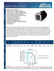
1.1.1 Servo drive<br />
7
1.2 Product Parts names<br />
1.2.1 Servo drive<br />
The part names of servo drive are shown as below:<br />
Panel display<br />
Display the status, alarms and parameter entering.<br />
Panel keys<br />
Use these buttons to set the parameters.<br />
Power on LED<br />
Lights when the power is on.<br />
Charging LED<br />
The indicator is highlighted when the power of main circuit is ON. Don’t<br />
touch servo since there will still be residual electric charge remains in the<br />
capacitor inside the Servo drive.<br />
Computer communication interface (COM)<br />
Communicate with computer.<br />
Input and output signal interface (1CN)<br />
Tie-ins for reference entering or sequence input and output signals.<br />
Encoder interface(2CN)<br />
To connect the terminals of encoder installed in servomotor.<br />
Power supply terminals and servomotor terminals<br />
Terminals used for power supply and to connect the servomotor<br />
industrial wire.<br />
8
Chapter 2<br />
Installation<br />
2.1 Servodrive<br />
EDB Series Servo drive is a base-mounted type servo controller. Incorrect installation will cause problems. Always<br />
observe the installation instructions described below.<br />
2.2.1 Storage<br />
When the Servo drive is to be stored with the power cable disconnected, store it in the following temperature range:<br />
Between −20°C and 85°C<br />
2.2.2 Installation sites<br />
Notes of operation installation are described as follows:<br />
Condition<br />
Installation in a Control Panel<br />
Installation Near a Heating Unit<br />
Installation Near a Source of Vibration<br />
Installation at a Site Exposed to Corrosive Gas<br />
Other Situations<br />
Safety notes<br />
Design the control panel size, unit layout, and<br />
cooling method so the temperature around the<br />
servo drive does not exceed 55 °C (131 °F)<br />
Minimize the heat radiating from the heating unit as<br />
well as any temperature rise caused by natural<br />
convection so the temperature around the servo<br />
drive does not exceed 55 °C (131 °F).<br />
Install a vibration isolator on the servo drive to<br />
avoid subjecting it to vibration.<br />
Corrosive gas does not have an immediate effect<br />
on the servo drive but will eventually cause the<br />
electronic components and contactor-related<br />
devices to malfunction. Take appropriate action to<br />
avoid corrosive gas.<br />
Do not install the servo drive in hot, humid<br />
locations or locations subject to excessive dust or<br />
iron powder in the air.<br />
9
2.2.3 Installation orientation<br />
Install the SERVODRIVE perpendicular to the wall as shown in the figure. The Servo drive must be oriented this<br />
way because it is designed to be cooled by natural convection or a cooling fan.<br />
2.2.4 Installation method<br />
When installing multiple Servos drives side by side in a control panel,<br />
observe the following installation method:<br />
█ Servo drive orientation<br />
Install the Servo drive perpendicular to the wall so the front panel containing connectors faces outward.<br />
█ Cooling<br />
As shown in the figure above, allow sufficient space around each Servo drive for cooling by cooling fans or natural<br />
convection.<br />
█ Side-by-side Installation<br />
When installing Servo drives side by side as shown in the figure above, allow at least 10 mm (0.39 in) between and at<br />
least 50 mm (1.97 in) above and below each Servo drive. Install cooling fans above the Servo drives to avoid<br />
excessive temperature rise and to maintain even temperature inside the control panel.<br />
█ Environmental Conditions in the Control Panel<br />
1. Ambient Temperature: 0 to 55°C (32 to 131° F)<br />
2. Humidity: 90% RH or less<br />
3. Vibration: 4.9 m/s2<br />
4. Condensation and Freezing: None<br />
5. Ambient Temperature for Long-term Reliability: 45 °C (113 °F) or less<br />
10
Chapter 3<br />
Wirings and connections<br />
3.1 Wirings and connections for main circuit<br />
Always observe the following notes when wire or connects the circuit.<br />
• Do not wire power lines and signal lines in the same duct or bundle them together. Wire<br />
such that signal lines are kept apart from power lines by at least 30 cm.<br />
• Twisted pair wire and multi-core twisted pair shielding wires should be used for signal<br />
lines, encoder (PG) feedback line.<br />
The length for wiring is 3m maximum for the reference input line, 20 m maximum for the PG<br />
feedback line.<br />
• Do not touch the power terminal even if power is turned off.<br />
High voltage may still remain in Servo drive. Perform inspection only after the CHARGE LED<br />
extinct.<br />
• Avoid frequently turning the power ON and OFF with the interval at least more than 1 min.<br />
Since the Servo drive has a capacitor in the power supply, a high charging current flows (for 0.2<br />
second) when the power is turned ON. Therefore, frequently turning the power ON and OFF<br />
causes the main circuit devices (such as capacitors and fuses) to deteriorate, resulting in<br />
unexpected problems.<br />
3.1.1 Names and Functions of Main Circuit Terminals<br />
Terminal symbol Name Description<br />
L1,L2,L3<br />
Main circuit power supply input<br />
terminal Three-phase 200-230VAC<br />
50/60HZ<br />
L1C, L2C<br />
Control circuit power supply input<br />
terminal Single-phase 200-230VAC<br />
50/60HZ<br />
U,V,W Servo Motor connection terminals Connects to servo motor<br />
Ground terminals<br />
Connects to the power supply ground<br />
terminals and servo motor ground<br />
terminal.<br />
B1, B2, B3 (EDB-08, Regenerative resistor connection Normally short B2 and B3 (for an internal<br />
EDB-10, and terminal<br />
regenerative resistor). Remove the wire<br />
11
EDB-15 don’t have<br />
B3 terminal.)<br />
1 2<br />
(EDB-08, EDB-10<br />
And EDB-15 doesn’t<br />
have those two<br />
terminals.)<br />
(EDB-08,<br />
EDB-10 And EDB-15<br />
doesn’t have this<br />
terminal.)<br />
DC reactor for harmonic<br />
suppression terminal<br />
Main circuit minus terminal<br />
between B2 and B3 and connect an<br />
external regenerative resistor between B1<br />
and B2 if the capacity of the internal<br />
regenerative resistor is insufficient.<br />
Normally short 1 and 2. If a<br />
countermeasure against power supply<br />
harmonic waves is needed, connect a DC<br />
reactor between 1 and 2.<br />
Normally not connected.<br />
3.1.2 Typical main circuit wiring example<br />
12
3.2 Input and output signal<br />
3.2.1 Connection of input and output signals<br />
13
3.2.2 Terminal layout of connector 1CN<br />
Pin<br />
number<br />
Name<br />
Description<br />
Pin<br />
number<br />
Name<br />
Description<br />
(*) 0:/COIN- 0: Positioning completed 19 V-REF Speed reference output<br />
1 /COIN+<br />
signal output ( speed<br />
2 (/V-CMP-)<br />
coincidence output)<br />
(/V-CMP+)<br />
20 SG 0V<br />
(*) 1:/TGON- 1:Run output<br />
21 T-REF Torque reference input<br />
5<br />
6<br />
/TGON+<br />
2:/S-RDY- 2:Servo ready output 22 SG 0V<br />
/S-RDY+<br />
Open-collector reference<br />
3:/CLT- 3:Torque limit output<br />
23 PL1<br />
(*)<br />
input power supply<br />
/CLT+<br />
7<br />
4:/BR- 4:Holding brake interlock<br />
8<br />
24 /PULS Reference pulse input<br />
/BR+<br />
output<br />
3 ALM- Alarm output 25 PULS Reference pulse input<br />
4 ALM+ Alarm output 26 /SIGN Reference sign input<br />
9 +24VIN I/O power supply input 27 SIGN Reference sign input<br />
10 /S-ON Servo ON input 28 PL2<br />
Open-collector reference<br />
input power supply<br />
11 /P-CON P control input 29 — —<br />
12 P-OT Forward overtravel input 30 PCO<br />
PG Frequency dividing<br />
output<br />
13 N-OT Reverse overtravel input 31 /PCO<br />
PG Frequency dividing<br />
output<br />
14 /ALM-RST Alarm reset output 32 PBO<br />
PG Frequency dividing<br />
output<br />
15 /CLR Clear input 33 /PBO<br />
PG Frequency dividing<br />
output<br />
16 /PCL<br />
Forward external torque<br />
PG Frequency dividing<br />
34 PAO<br />
limit<br />
output<br />
17 /NCL<br />
Reverse external torque<br />
PG Frequency dividing<br />
35 /PAO<br />
limit<br />
output<br />
18 SG 0V 36 SG 0V<br />
Note:<br />
1. Do not use vacant pins for relay or other purposes.<br />
2. Connect the shielded twisted pairs of I/O signals to connector frame.<br />
3. Allocate and define function for pin 1CN-1, 2, 1CN-5, 6, 1CN-7, 8 according to parameter Pn053, Pn054, Pn055.<br />
14
3.2.3 I/O signal names and functions<br />
█ Input signal<br />
Signal<br />
name<br />
Pin<br />
number<br />
Function<br />
+24VIN 9 Control power supply input for sequence signals: Users<br />
must provide the +24 V power supply.<br />
Reference<br />
4.2.4<br />
Allowable Voltage range: +11V ~ +25V<br />
/S-ON 10 Servo ON:Servo power on<br />
4.5.2<br />
/P-CON 11 Function differs with control modes.<br />
P-OT 12 Forward drive prohibited 4.1.2<br />
N-OT 13 Reverse drive prohibited<br />
/ALM-RST 14 Alarm reset: Releases the servo alarm state. 4.5.1<br />
/CLR 15<br />
Clear signal input: Clears the positional error pulse during 4.2.2<br />
position control.<br />
/PCL 16 Forward external torque limit ON 4.1.3<br />
/NCL 17 Reverse external torque limit ON 4.1.3<br />
V-REF 19 Speed reference input: ±10V 4.2.1<br />
(20)<br />
T-REF<br />
21<br />
4.2.8<br />
Torque reference input: ±10V<br />
(22)<br />
23 Open-collector reference power supply: Pull-up power is 4.2.2<br />
28 supplied when PULS, and SIGN reference signals are<br />
PL1<br />
open-collector outputs (+5~24 VDC power supply is built<br />
PL2<br />
into the Servo drive).<br />
24<br />
Input mode is set from the<br />
4.2.2<br />
/PULS<br />
PULS<br />
/SIGN<br />
SIGN<br />
25<br />
26<br />
27<br />
Reference pulse input:<br />
line driver or open collector<br />
following pulses.<br />
*signals +pulse string<br />
*CCW/CW pulse<br />
* • Two-phase pulse (90°<br />
phase differential)<br />
Note: 1. Pin numbers in parentheses () indicate signal grounds.<br />
15
█ Output signal<br />
Signal name<br />
Pin<br />
Function<br />
Reference<br />
number<br />
0:/COIN-<br />
/COIN+<br />
(/V-CMP-)<br />
1<br />
2<br />
0:Positioning completed signal output<br />
( Speed coincidence output )<br />
1:Detection during servomotor rotation:<br />
4.5.3<br />
4.5.4<br />
4.5.5<br />
4.5.6<br />
4.1.3<br />
(/V-CMP+)<br />
5<br />
6<br />
2:Servo ready<br />
4.4.4<br />
1:/TGON-<br />
3:Torque limit detection<br />
/TGON+<br />
4:Brake interlock output<br />
2:/S-RDY-<br />
Customer constant Pn053 sets output of CN1-7,8;<br />
/S-RDY+<br />
3: /CLT-<br />
7<br />
8<br />
Customer constant Pn054 sets output of CN1-1,2;<br />
Customer constant Pn055 sets output of CN1-5, 6.<br />
/CLT+<br />
4: /BR-<br />
/BR+<br />
ALM-<br />
ALM+<br />
PAO<br />
/PAO<br />
PBO<br />
/PBO<br />
PCO<br />
/PCO<br />
3<br />
4<br />
34<br />
35<br />
32<br />
33<br />
30<br />
31<br />
(18,36)<br />
Servo alarm: Turns OFF when an error is detected. 4.5.1<br />
Phase-A Converted two-phase pulse (phases A 4.2.3<br />
signal and B) encoder output signal and<br />
zero-point pulse (phase C) signal:<br />
Phase-B RS-422 or the equivalent<br />
signal<br />
Phase-C<br />
signal<br />
FG<br />
Shell<br />
Connected to frame ground if the shield wire of the<br />
I/O signal cable is connected to the connector shell.<br />
—<br />
Note: 1. Pin numbers in parentheses () indicate signal grounds.<br />
16
3.2.4 Interface Circuit<br />
This section shows examples of Servo drive connection to the host controller.<br />
█ Interface for Analog reference Input Circuits<br />
Analog signals are either speed or torque reference signals. The reference input resistor is about 40kΩ and Max.<br />
Allowable voltage of input signals is ±10V.<br />
Speed reference input circuit: Torque reference input circuit :<br />
█ Sequence Input Circuit<br />
The sequence input circuit interface connects through a relay or open-collector transistor circuit. Select a low current<br />
relay otherwise a faulty contact will result.<br />
█ Line Driver Output Circuit<br />
Encoder serial data converted to two-phase (phases A and B) pulse output signals (PAO, /PAO, PBO, /PBO),<br />
zero-point pulse signals (PCO, /PCO) are output via line-driver output circuits. Normally, the Servo drive uses this<br />
output circuit in speed control to comprise the position control system at the host controller. Connect the line-driver<br />
output circuit through a line receiver circuit at the host controller.<br />
█ Sequence output circuit<br />
Output signals of Servo alarm, Servo ready and other sequences are consist of photocoupler output circuit, please<br />
connect to relays.<br />
17
3.3 wiring encoders<br />
3.3.1 Connecting an Encoder (2CN) and Output Signals from<br />
the servodrive<br />
3.3.2 Encoder Connector (CN2) Terminal Layout<br />
2CN terminals layout is as follows:<br />
Pin Color<br />
Pin Color<br />
Name Description<br />
No.<br />
No.<br />
Name Description<br />
1 Blue PA PG inputs phase A 11 Grass green PU PG input phase U<br />
2 Pink /PA PG input /phase A 12 Brown /PU PG input phase U<br />
3 Yellow PB PG input phase B 13 Green PV PG input phase V<br />
4 Purple /PB PG input phase /B 14 Light purple /PV PG input phase /V<br />
5 White PC PG input phase C 15 Grey PW PG input phase W<br />
6 Light green /PC PG input phase /C 16 Light blue /PW PG input phase /W<br />
7<br />
17 black<br />
PG power supply<br />
8 Red PG5V 18<br />
SG PG power supply 0V<br />
+5V<br />
(orange)<br />
9 19<br />
10 — — — 20 — — —<br />
18
3.4 Wiring servo motor<br />
3.4.1 Encoder Connector Terminal Layout<br />
Pin No. Color Description<br />
Red<br />
1<br />
+5V(power supply)<br />
2 Black (orange) 0V(power supply)<br />
3 Blue A channel output<br />
4 Pink /A channel output<br />
5 Yellow B channel output<br />
6 Purple /B channel output<br />
7 White C channel output<br />
8 Light blue /C channel output<br />
9 Grass blue U channel output<br />
10 Brown /U channel output<br />
11 Green V channel output<br />
12 Light purple /V channel output<br />
13 Grey W channel output<br />
14 Light blue /W channel output<br />
3.4.2 Dynamic power Connector Terminal layout<br />
Pin No. Color Description<br />
1<br />
Blue<br />
FG(Frame grounding)<br />
2 Pink Phase U<br />
3 Yellow Phase V<br />
4 Green Phase W<br />
19
3.5 Typical wiring example<br />
20
3.5.1 Position control mode<br />
21
3.5.2 Speed control mode<br />
22
3.5.3 Torque control mode<br />
23
Chapter 4<br />
Parameter Setting and function description<br />
4.1 Setting Parameters according to mechanical features<br />
4.1.1 Changing the Direction of Motor Rotation<br />
This Servo drive provides a reverse rotation mode in which the direction of rotation can be reversed without<br />
altering the servomotor wiring. With the standard setting, forward rotation is defined as counterclockwise (ccw) rotation<br />
viewed from the drive end. If reverse rotation mode is selected, the direction of motor rotation can be reversed without<br />
other conditions being changed. The direction (+/−) of axial motion is reversed and others remain unchanged.<br />
Standard setting<br />
Reverse mode<br />
FW<br />
run<br />
Ref<br />
RV<br />
run<br />
Ref<br />
█ Setting Reverse Rotation Mode<br />
Select the rotating direction by setting parameters below:<br />
Parameter .No.<br />
Name and description<br />
Unit Setting<br />
range<br />
Default<br />
Pn006 Rotation Direction Selection<br />
— 0~1 0<br />
[0] Forward rotation is defined as counterclockwise<br />
rotation when viewed from the load side. (Standard<br />
setting)<br />
[1] Forward rotation is defined as clockwise rotation<br />
when viewed from the load side. (Reverse rotation<br />
mode)<br />
Note: After changing these parameters, turn OFF the main circuit and control power supplies and then turn them ON<br />
24
again to enable the new settings.<br />
4.1.2 Setting overtravel limit<br />
The overtravel limit function forces the moving part of the machine to stop when it exceeds the movable range.<br />
█ Using the Overtravel Limit Function<br />
To use the overtravel limit function, connect the following overtravel limit switch input signal terminals to pins of<br />
1CN connector correctly.<br />
→Input P-OT 1CN-12<br />
Forward Rotation Prohibited (Forward Overrun)<br />
→Input N-OT 1CN-13<br />
Reverse Rotation Prohibited (Reverse Overrun)<br />
For linear motion, connect a limit switch to prevent damage to the machine.<br />
Input signal “ON/OFF” status are shown as follows:<br />
Signals Status Input voltage Description<br />
P-OT<br />
ON 1CN-12:“L” level Forward rotation allowed. Normal operation status.<br />
OFF 1CN-12:“H” level Forward rotation prohibited (reverse rotation allowed).<br />
N-OT<br />
ON 1CN-13:“L” level Reverse rotation allowed. Normal operation status.<br />
OFF 1CN-13:“H” level Reverse rotation prohibited (forward rotation allowed).<br />
█<strong>Spec</strong>ifying whether Input Signals for Overtravel are to be used<br />
Use the following parameters to specify whether input signals for overtravel is to be used. Default value is using.<br />
Para. No<br />
Name and description<br />
Unit Setting<br />
range<br />
Default<br />
Pn001 Uses the P-OT input signal for prohibiting forward rotation or not — 0~1 0<br />
[0] Uses the P-OT input signal for prohibiting forward rotation. (Forward<br />
rotation is allowed when 1CN-12 is at 0 V.)<br />
[1] Does not use the P-OT input signal for prohibiting forward rotation.<br />
(Forward rotation is always allowed. This has the same effect as<br />
shorting 1CN-12 to 0 V.)<br />
Pn002 Uses the N-OT input signal for prohibiting reverse rotation or not<br />
[0] Uses the N-OT input signal for prohibiting reverse rotation.<br />
(Reverse rotation is prohibited when 1CN-13 is open. Reverse rotation<br />
is allowed when 1CN-13 is at 0 V.)<br />
— 0~1 0<br />
25
[1] Does not use the N-OT input signal for prohibiting reverse rotation.<br />
(Reverse rotation is always allowed. This has the same effect as<br />
shorting 1CN-13 to 0 V.)<br />
Note: When the servomotor stops due to overtravel during position control, the position error pulses<br />
are held. A clear signal input is required to clear the error pulses.<br />
When P-OT and N-OT are not used, short wiring could be as easy as shown.<br />
█Stop motor when overtravel occurs<br />
Please set user constant according to the method of stopping the motor when<br />
overtravel function is enabled.<br />
Para. Description Para. range Default<br />
Pn004 Stop the mode when Servo OFF、alarm or overtravel occurs 0~5 0<br />
Para.<br />
Descriptions<br />
[0] DB stops the motor and then brake released<br />
[1] Coast to a stop:<br />
[2] Enable DB when Servo off; apply plug braking when OT occurs, Servo off after stop<br />
[3] Coast to stop when Servo off; apply plug braking when OT occurs, Servo off after stop<br />
Pn004<br />
[4] Enable DB when Servo off; apply plug braking when OT occurs and put at zero clamp after<br />
stop<br />
[5] Coast to stop when Servo off; apply plug braking when OT occurs and put at zero clamp<br />
after stop<br />
Note: Refer to 4.4.2 Dynamic brake about details of DB.<br />
Para. Description Unit Setting range Default<br />
Pn030<br />
plug braking stop torque<br />
1% 0~300<br />
300<br />
█Selecting the Motor Stop Method when Servo is OFF<br />
The servo drive will disenable all the servo functions at following condition:<br />
1. /S-ON input signal (1CN-10) is OFF<br />
2. Servo alarms triggered<br />
3. Power OFF.<br />
Setting Pn004 to select stop modes according to the demand<br />
4.1.3 Limiting Torque<br />
The servo drive could use the following method to limit torque:<br />
26
Grade 1: Limit the Max output torque to protect press and parts. (Limit internal torque)<br />
Grade 2: Limit torque to move to desired position (limit external torque)<br />
Para. Name and description Unit Setting range Default<br />
Pn026 Forward torque internal limit % 0~300 300<br />
Pn027 Reverse torque internal limit % 0~300 300<br />
Pn028 Forward torque external limit % 0~300 100<br />
Pn029 Reverse torque external limit % 0~300 100<br />
█ Grade 1 set the internal torque limit<br />
Adjust forward and reverse torque limit by setting<br />
parameters (Pn026, Pn027) for limiting torque. After setting the limit,<br />
“/CLT” will output when reach the limit value. If the torque<br />
limit is set<br />
higher than the maximum torque of the servomotor, the<br />
maximum<br />
torque of the servomotor is used.<br />
Example: for mechanical protection<br />
█ Grade 2 set the external torque limit<br />
First set the torque limit of user constant (Pn028, Pn029), then enable the limit with contact input signal. Both<br />
forward and reverse torque could be set separately.<br />
->Input /PCL(1CN-16)<br />
->Input /NCL(1CN-17)<br />
input external forward torque limit<br />
input external forward torque limit<br />
Speed ,torque control ,position control<br />
Speed ,torque control ,position control<br />
Signal Status Input voltage Description Setting<br />
/PCL<br />
ON 1CN-16:“L”level External torque limits valid when forward rotation. Limit: Pn028<br />
OFF 1CN-16:“H”level Internal torque limits valid when forward rotation. Limit: Pn026<br />
/NCL ON 1CN-17:“L”level External torque limits valid when reverse rotation. Limit: Pn029<br />
27
OFF 1CN-17:“H”level Internal torque limits valid when forward rotation. Limit: Pn027<br />
Set or use torque limit according to external contact input, “/CLT” signal will output if exceeding torque limit. Please<br />
refer to 4.2.10 Torque Limiting Using an Analog Voltage Reference for limiting torque using analog voltage output.<br />
Note:<br />
• Do not set the torque limit higher than Max. torque of motor.<br />
• Too small a torque limit setting will result in insufficient torque during acceleration and<br />
deceleration.<br />
Note:<br />
Please select proper mode for allocating “/PCL, /NCL” signals as torque limit input.<br />
Parameter Name Range Default Application<br />
Pn041 control mode selection 0~13 0 Speed, torque control, position control<br />
“/PCL, /NCL” can’t be allocated as torque limit input in internally set speed control mode.<br />
Pn041 setting Description Possible input signal<br />
0,1,2,7,8,9,<br />
10,11,12,13<br />
3,4,5,6<br />
Does not use /P-CON(CN1-11) •PI control /P control switch<br />
internal speed<br />
• switch control mode<br />
selection<br />
• Switch to zero-clamp valid/ invalid<br />
•Switch INHIBIT valid /invalid<br />
•Step changing output<br />
/PCL(CN1-12) • Forward external torque limit output<br />
• looking for reference point<br />
/NCL(CN1-13) • reverse external torque limit output<br />
• looking for reference point<br />
Use internal speed /P-CON /PCL /NCL Speed setting<br />
selection Direction 0 0 Control mode switch<br />
selection 0 1 SPEED1(Pn038)<br />
0:forward<br />
1 1 SPEED2(Pn039)<br />
1 0 SPEED3(Pn040)<br />
1:reverse<br />
Note: 0: OFF (H level), 1: ON (L level)<br />
Application of CLT signal:<br />
The application of output signal /CLT is as follows:<br />
28
->Output /CLT<br />
Torque limit detection output<br />
Speed, torque control, position control<br />
Indicates the output torque (current) of motor is limited.<br />
/CLT+ when ON, “L” level Motor output torque under limit<br />
(internal torque reference is higher than setting value )<br />
/CLT+ when OFF “H” level No torque limit<br />
(internal torque reference is lower than setting value )<br />
Please use the following user constants to define output signals and pins when using /CLT signal.<br />
Para. No. Name and description Setting range Default<br />
Pn053 Select output signals 1CN-7,8 functions 0~4 0<br />
Pn054 Select output signals 1CN-1,2 functions 0~4 1<br />
Pn055 Select output signals 1CN-5,6 functions 0~4 2<br />
The pin definitions of Pn053, Pn054 and Pn055 parameter settings are as follows:<br />
0 /COIN(/V-CMP) output<br />
1 /TGON rotation detection output<br />
2 /S-RDY servo ready output<br />
3 /CLT torque limit output<br />
4 BK brake interlock output<br />
4.2 Setting Parameters According to Host Controller<br />
4.2.1 Speed Reference<br />
Analog reference<br />
Input a speed reference by using the following input signal “speed reference input.”<br />
29
→ Input V-REF 1CN- 19<br />
Speed reference input<br />
→ Input SG 1CN- 20 Signal ground<br />
Use when in speed control (analog reference) (Pn041=0, 4, 7, 9, 10)<br />
For general speed control, always wire the VREF and SG terminals. Motor speed is controlled in proportion to the<br />
input voltage between V-REF and SG.<br />
█ Standard Example<br />
Changing “Pn-012” may modify range of speed reference.<br />
Pn-012 = 150: This setting means that 10 V is equal to rated speed (1500r/min).<br />
<strong>Spec</strong>ific example is as follows:<br />
Speed reference input Rotation direction Rotation speed<br />
+10V Forward Rated speed 1500r/min<br />
+1V Forward<br />
(1/10) Rated speed,150r/min<br />
-3V Reverse<br />
(3/10) Rated speed,450r/min<br />
█ Example of input circuit<br />
For noise control, always use multi-twisted cables.<br />
Connect V-REF and SG to speed reference output terminal when host controller is used for position control.<br />
30
Now please refer to the specification of output voltage to adjust “Pn012”.<br />
Adjust the input gain of speed reference by setting the following parameter:<br />
Para .No. Name and description Unit Setting range Default<br />
Pn012 Speed reference gain (r/min)/V 0~2500 150<br />
Speed reference is input from V-REF (1CN-19).Set the parameters according to the output of host controller or<br />
external circuit. The default setting is adjusted to be allowed by output voltage 10V rated speed.<br />
Note:<br />
• Max allowable voltage is ±10VDC speed reference input end (between 1CN-19 and 20).<br />
Select one of the following four control modes:<br />
Para. Name Range Default Application<br />
Pn041 Control mode selection 0~13 0 Speed, torque control, position control<br />
Pn041<br />
0<br />
Control mode<br />
Speed control (analog reference)<br />
Normal speed control<br />
• V-REF(1CN-19) input speed reference<br />
• Switching P/PI control mode using signal<br />
/P-CON(CN1-11)<br />
1CN-11:OFF PI control<br />
ON<br />
P control<br />
31
7<br />
Position control (pulse reference)Speed<br />
control (analog reference)<br />
• Inputs speed reference from V-REF(1CN-19)<br />
• Switching control mode by using signal<br />
/P-CON(1CN-11)<br />
1CN-11:OFF Position control (pulse reference)<br />
ON Speed control (analog reference)<br />
Note: /P-CON(1CN-11) is no longer used to<br />
switching modes of P/PI in speed control and<br />
position control mode.<br />
9<br />
Torque control(Analog reference) Speed control (Analog reference)<br />
Switch between Torque control (analog reference)<br />
and speed control (analog reference)<br />
• Inputs speed reference or speed limit from<br />
V-REF(1CN-19)<br />
• Inputs one of the following: torque reference,<br />
Torque feed forward reference or torque limit from<br />
T-REF(1CN-21)<br />
• Switching torque control and speed control<br />
By /P-CON(1CN-11)<br />
1CN-11 OFF: torque control ;ON:speed control<br />
Torque control (when /P-CON is OFF)<br />
• Torque controls according to T-REF.<br />
• V-REF may provide speed control, (when Pn007=1), limit forward and reverse rotating speed<br />
according to V-REF (+).<br />
• Limit Max. speed from user constant Pn042<br />
Speed control(when /P-CON is ON)<br />
•user constant Pn010、Pn011is set as follows:<br />
User constant<br />
Speed input reference<br />
Torque input reference<br />
Observation<br />
Pn010<br />
Pn011<br />
V-REF(1CN-19)<br />
T-REF(1CN-21)<br />
32
0 0 Simple speed control<br />
Speed reference<br />
Not used<br />
-<br />
1 speed control with torque feed forward Set Pn010<br />
Speed reference<br />
Torque feed forward<br />
refer to 4.2.9<br />
1 0 Torque limit speed control offered by analog voltage reference Refer to<br />
Speed reference<br />
Torque limit<br />
4.2.10<br />
For details<br />
Speed control ( Analog reference zero clamp<br />
10<br />
speed control with zero clamp function<br />
·Inputs V-REF(1CN-19) from speed control<br />
·Select zero clamp by /P-CON(1CN-11)<br />
1CN-11:ON zero clamp valid<br />
OFF zero clamp invalid<br />
Zero clamp acting when the following condition<br />
fulfilled<br />
1:/P-CON is ON<br />
2:motor speed is below Pn033 setting value<br />
█ / P-CON signal application<br />
Pn041 setting<br />
Meaning of /P-CON<br />
0,1 Switch between P and PI<br />
2 (not used)<br />
3,4,5,6 change the rotation direction of internally setting<br />
speed chosen<br />
7,8,9 Change control modes<br />
10 Switch between zero clamp valid and invalid<br />
11 Switch between INHIBIT valid and invalid<br />
33
12 Step changing signal<br />
13 (not used)<br />
Parameter speed reference<br />
Servo motor rotates constantly according to set speed and direction of Pn048 and Pn049 under parameter speed<br />
control mode (parameter reference Pn041= 13).<br />
Para. No. Name and description Unit Setting range Default<br />
Pn048 Speed level when parameter speed reference function R/min<br />
0~2500<br />
500<br />
Pn049<br />
Rotation direction when parameter speed reference function<br />
0:Forward ;1: Reverse<br />
0~1<br />
0<br />
4.2.2 Position reference<br />
Position reference includes: reference pulse input, reference sign input and error counter clear input. There are<br />
various applications, please set the best input reference in the system established.<br />
█ Move Reference by Pulse Input<br />
Inputs a move reference by pulse input<br />
Position reference can correspond<br />
to the following three types of output<br />
form:<br />
● Line driver output<br />
● +24V Open collector output<br />
● +12V, +5V Open collector output<br />
Connection Example 1: Line Driver Output<br />
Line Driver Used:<br />
AM26LS31, SN75174 manufactured by<br />
Texas Instruments Inc., or<br />
MC3487 or equivalent.<br />
Connection Example 2: Host controller is Open-Collector Output with 24VDC power supply<br />
34
Connection Example 3: Host controller is Open-Collector Output with 12VDC or 5VDC power supply<br />
Sets the value of limiting resistor R1 according to following requirement.<br />
Input current I=10~15mA<br />
• When Vcc is 12 V, R1 = 510 kΩ<br />
• When Vcc is 5 V, R1 = 180 Ω<br />
█ Selecting the Reference Pulse Form<br />
→input PULS 1CN- 25 Reference Pulse Input<br />
→input /PULS 1CN-24 Reference Pulse Input<br />
35
→input SIGN 1CN-27 Reference Sign Input<br />
→input /SIGN 1CN-26 Reference Sign Input<br />
The motor only rotates at an angle proportional to the input pulse.<br />
Select “reference pulse status” with the following parameters “Pn008 and Pn009”.<br />
Parameter Code Name Unit Range Default<br />
Pn008 --<br />
Reference pulse form<br />
[0] Sign + Pulse<br />
[1] CW+CCW<br />
[2] A-phase + B-phase(x1 multiplication)<br />
-- 0~4 0<br />
[3] A-phase + B-phase(x2 multiplication)<br />
[4] A+B(x4 multiplication)<br />
Pn009 --<br />
Input signals:<br />
[0] does not invert PULS reference pulse<br />
logic, does not invert SIGN reference<br />
pulse logic<br />
[1] does not invert PULS reference pulse<br />
logic, inverts SIGN reference pulse logic<br />
[2] inverts PULS reference pulse logic, does<br />
not invert SIGN reference pulse logic<br />
[3] inverts PULS reference pulse logic,<br />
inverts SIGN reference pulse logic<br />
-- 0~3 0<br />
Sets the pulse form according to the host controller specifications<br />
Pn008<br />
Reference<br />
Input<br />
Motor Forward Run<br />
Motor reverse Run<br />
pulse form<br />
Pulse<br />
Reference<br />
Reference<br />
Multiplier<br />
0 Sign +<br />
pulse<br />
-<br />
train<br />
1 CW-CCW<br />
pulse<br />
-<br />
2 Two phase ×1<br />
3 Pulse train ×2<br />
4 with 90°<br />
difference<br />
×4<br />
36
Select if the<br />
input signal<br />
converted<br />
or not when<br />
setting<br />
parameter<br />
Pn009<br />
according<br />
to your<br />
needs,<br />
Pulse Multiply Function<br />
█ Input<br />
When the reference form is two-phase pulse train with 90° phase difference, the input pulse multiply function can be<br />
used.<br />
The electronic gear function can also be used to convert input pulses.<br />
Allowable Voltage Level and Timing for Reference Pulse Input<br />
█ Cleaning the Error Counter<br />
→ Input /CLR 1CN-15 Error Counter Clear Input<br />
Setting the /CLR signal to “L” level does the following:<br />
• Sets the error counter inside the Servo drive to “0”.<br />
• Prohibits position loop control.<br />
In the position control, when servo is OFF, pulse will still remains. Therefore when power is on again (S-ON) pulse<br />
signals have to be cleared or clear position move automatically when Servo is OFF by setting user constant Pn005.<br />
Parameter Name & descriptions Setting range Default<br />
37
Pn005<br />
0: S-OFF, clear pulse<br />
1: S-OFF, not clear pulse<br />
0-1 0<br />
█ Position reference one rank filter wave<br />
Position reference one rank filter wave entitle the improvement of pulse reference form designated by the system,<br />
thus enhance the stability of position control. But if “position reference position one rack filter time constant (Pn024)” set<br />
too high, dynamic function of the system might be decreased.<br />
Parameter Name Unit Setting range Default<br />
Pn024 Position reference 0.1mS 0-32767 0<br />
one rank filter wave<br />
time constant<br />
4.2.3 Encoder signal output<br />
Encoder output signals divided inside the Servo drive can be output externally. These signals can be used to form a<br />
position control loop in the host controller.<br />
The output circuit is for line driver output. Connect each signal line according to the following circuit diagram.<br />
38
Note: dividing means converting an input pulse train from the encoder mounted on the motor according<br />
to the preset pulse density and outputting the converted pulse. The unit is pulses per revolution.<br />
█Output signal<br />
Output → PAO 1CN- 34 Encoder Output Phase A For Speed/Torque Control and Position Control<br />
Output → /PAO 1CN- 35 Encoder Output/ Phase A For Speed/Torque Control and Position Control<br />
Output → PBO 1CN- 32 Encoder Output Phase B For Speed/Torque Control and Position Control<br />
Output → /PBO 1CN- 33 Encoder Output Phase /B For Speed/Torque Control and Position Control<br />
Output → PCO 1CN- 30 Encoder Output Phase C For Speed/Torque Control and Position Control<br />
Output → /PCO 1CN- 31 Encoder Output Phase /C For Speed/Torque Control and Position Control<br />
Output → SG 1CN- 18 Signal grounding<br />
Always connect these signal terminals when a position loop is formed in the host controller to perform position control.<br />
Connect SG to host controller 0V.<br />
The output signals forms are shown in the following diagram:<br />
█ Setting the Pulse Dividing Ratio<br />
Set the pulse dividing ratio in the following parameter.<br />
Parameter Name Unit Range Default<br />
Pn021 PG Dividing Ratio Setting P/R 1~2500 2500<br />
Sets the number of output pulses for PG output signals (PAO, /PAO, PBO and /PBO).<br />
Pulses from motor encoder (PG) are divided by the preset number of pulses before being output. The number of<br />
output pulses per revolution is set in this parameter.<br />
Set this value according to the reference unit of the machine or controller to be used. The setting range varies<br />
according to the encoder used.<br />
39
Note<br />
• After changing the parameter setting, always turn the power OFF, then ON.<br />
40
4.2.4 Contact I/O Signals<br />
Please wiring contact I/O signals that controls servo drive properly.<br />
█ Contact Input Signal Terminal Connections<br />
Connect these signal terminals as necessary.<br />
Note:<br />
Provide an external I/O power supply separately. There are<br />
no power terminals available from the servo drive outputs<br />
signals externally.<br />
·External power supply : DC24V±1V,50mA or more<br />
It is recommended that this external power supply be the<br />
same type as for the output circuit.<br />
And the sequence input circuit operation voltage of +24V<br />
█<br />
ranges from +11V~+25V. +12V power supply could also<br />
be applied, but bad contact will occur when the contacts are<br />
mechanical and in small current.<br />
Contact Output Signal Terminal Connections<br />
→ Input +24VIN 1CN- 9<br />
External I/O power supply input<br />
41
Note :<br />
Provide an external I/O power supply separately. There are no power terminals available from the servo<br />
drive outputs signals externally. It is recommended that external power supply be the same type<br />
as for the output circuit.<br />
4.2.5 Position control (parameter reference)<br />
Position control under parameter reference (parameter Pn041= 12). In this mode, servo drive could position with a<br />
single axes without host controller.<br />
There are 16 position control points with each could set move distance, running speed, constants for acceleration<br />
and deceleration and the stop time when positioning completed. Two speeds (1. speed moving towards distance<br />
switch “speed of looking for reference point”. 2. Speed moving away from distance switch “moving speed” of reference<br />
points could be set as:<br />
Two position modes: 1. Absolute position mode 2. Relative position mode<br />
Two running modes: 1. Circling mode 2. Non-circling mode<br />
Two step switching method: 1. Delay step switching 2. /P-CON signal switching<br />
Method of looking for reference points: 1. Forward direction 2. Reverse direction<br />
█ Adjusting offset<br />
Offset of each points has two correspondent parameters: one unit of the parameter is 【x 10000 reference pulse】<br />
and the other is 【x 1 reference pulse】. Setting range of both parameters is: (-9999----+9999), while offset value equals<br />
sum of those two values.<br />
For example:<br />
No.0 offset correspond to parameter Pn059 【x 10000 reference pulse】 and Pn060 【x 1 reference pulse】. Set<br />
Pn059 = 100, Pn060=-100.<br />
No.0 offset value = Pn059x10000 reference pulse + Pn060x1 reference pulse<br />
= 100x10000 reference pulse + (-100)x1 reference pulse<br />
= 999900 reference pulse<br />
With the same principle, we can conclude: in order to get the same results, we also can set Pn059 = 99 and Pn060<br />
= 9900.<br />
Thus, we can see when the two parameters are not zero; we can get same result by two ways: one is to set the two<br />
parameters both negative or both positive, or one negative the other positive.<br />
It is no doubt that setting the parameter could be realized by communication. In computer, corresponding offset<br />
value could be set according to above mentioned method, and one also can set the value directly: choose<br />
“independent position running” in the “operation” menu, then set the value without considering sum of two parameter.<br />
(Refer to PC communication application software------- SP Windows help documents for detailed steps.)<br />
■ Speed<br />
42
Speed mention here refers to the steady speed during motor running, which is similar to the pulse frequency given<br />
from external in ordinary position control. However, this speed has nothing to do with electronic gear; it is just actual<br />
speed of the motor.<br />
■ One rank filter time constant<br />
Same as position reference one rank filter time constant Pn024 during ordinary position control (refer to 4.2.2 for<br />
details)<br />
■ Time for change steps after desired position reached<br />
Apply internally delay of changing steps to valid this parameter, that is to set Pn051= 0.<br />
Para. No. Name and description Setting range Default<br />
Pn051<br />
0: delay changing steps, no need of start signal.<br />
1: change steps by /P-CON, no need of start signal<br />
2. delay changing steps, need start signal. (/PCL or /NCL)<br />
3. change steps by /P-CON, need start signal.(/PCL or /NCL)<br />
0~1 0<br />
Time for change steps outputs from positioning completed signal CON/, from Servo ON, or from the time when<br />
reference point is found till Servo perform the program to control position of the point. Such period of time depends on<br />
step changing time required by a point number among start point in program.<br />
For example, the start point of the program Pn219=1, then the step changing time depends on the value of No.0<br />
step changing time Pn187. It could be deduced by analogy when program start points are from 2-15. But when<br />
Pn219=0, then the delay time is No.15 point changing steps time Pn202. During this time and time before when Servo<br />
is OFF, the step display in monitor is the program start point minus one. If Pn219=0, then the “current point “displays in<br />
monitor is “-1”. If Servo OFF after point control program has been performed, then actual step will be displayed in the<br />
monitor. Looking for a new reference point, then the “current step” will display the step before program start point.<br />
When running point control program, if error counter is set as “not clear error counter when Servo OFF”, then the<br />
error counter might flood. If it does not flood, then the servo drive will probably run at the max. running speed when<br />
Servo ON again. PLEASE PAY ATTENTION TO THE SAFETY OF INSTRUMENT.<br />
Para.<br />
No.<br />
Pn005<br />
Name and description<br />
0: clear the error counter when S-OFF<br />
1: not clear the error counter when S-OFF<br />
Setting range<br />
Default<br />
0~1 0<br />
■ Looking for the reference point<br />
Looking for the reference point is for establishing a zero physical point of the operating platform, which is used as<br />
zero point in the coordinates during point position control. And users may choose to find a reference point either in<br />
forward side or reverse side.<br />
How to find a reference point<br />
Mount a limit switch in the forward or reverse side, find a reference point in the forward direction after connect to<br />
43
PCL and in the reverse direction after connect to /NCL. When the operating platform bump into the limit switch, motor<br />
will first stop according to the way set by Pn004 and then rotates again against limit switch. When the operating<br />
platform completely departed from limit switch and put motor at the position of first photo encoder Phase C pulse.<br />
Then position of operating platform is set to be zero point of coordinates.<br />
How to find related parameters of reference point<br />
Speed that towards limit switch is called “speed of looking for reference point “, and the speed moving away from<br />
limit switch is called “ moving speed”. These two speeds could be set by following parameters:<br />
Para. No. Description Unit Setting range Default<br />
speed of looking for reference point<br />
Pn221<br />
(bump the limit switch)<br />
r/min 0~2500 1500<br />
Pn222<br />
Moving speed (move away from limit<br />
switch)<br />
r/min 0~2000 30<br />
Usually, set speed of looking for reference point (Pn221) high and Moving speed (Pn222) low. Note: if moving<br />
speed is too high, precision of finding a reference point would be affected.<br />
Besides, /PCL and /NCL is no longer functioned to limiting external current when looking for a reference point.<br />
■ Related user constants<br />
Para.<br />
Description<br />
No.<br />
Choose between cycle run and single run.<br />
0: cycle run, /PCL as start signal, /NCL reverse to look<br />
for reference point.<br />
1: single run, /PCL as start signal, /NCL reverse to<br />
Pn050 look for reference point.<br />
2. cycle run, /NCL as start signal, /PCL reverse to look<br />
for reference point.<br />
3. single run, /NCL as start signal, /PCL reverse to<br />
look for reference point.<br />
0: delay changing steps, no need of start signal.<br />
1: change steps by /P-CON, no need of start signal<br />
2. delay changing steps, need start signal. (/PCL or<br />
Pn051<br />
/NCL)<br />
3. change steps by /P-CON, need start signal.(/PCL or<br />
/NCL)<br />
Observation<br />
Changing steps will be performed till<br />
the end point completed and the<br />
next change will start from the start<br />
point during multi-points cycle run,<br />
Point control program will not<br />
change steps after the end point<br />
completed during multi- points single<br />
run.<br />
Change steps by external /P-CON<br />
signals. The signal will be valid when<br />
drive output reach to desired<br />
position. And when signals of<br />
changing the signals valid, then<br />
steps will be changed by<br />
consequence from start point to end<br />
point.<br />
44
Pn052<br />
0: incremental<br />
1: absolute<br />
Incremental: relative moving<br />
distance (distance from current<br />
point to next point) programming<br />
Absolute: absolute moving<br />
distance(distance between<br />
operating platform and the<br />
reference point) programming.<br />
45
█ Wirings and connections in points control mode<br />
46
4.2.6 Electronic gear<br />
The electronic gear function enables the motor travel distance per input reference pulse to be set to any value. It<br />
allows the host controller to perform control without having to consider the machine gear ratio and the number of<br />
encoder pulses.<br />
█ Setting the Electronic Gear<br />
Calculate the electronic gear ratio (B/A) according to the procedure below and set the value in Pn022 and<br />
Pn023.<br />
1. Check the machine specifications.<br />
Items related to electronic gear:<br />
− Gear ratio<br />
− Ball screw pitch<br />
− Pulley diameter<br />
2. Check the number of encoder pulses for the Servomotor.<br />
3. Determine the reference unit to be used.<br />
Reference unit is the minimum unit of position data used<br />
for moving the load. (Minimum unit of reference from host controller)<br />
Examples:<br />
0.01 mm, 0.001 mm, 0.1°, 0.01 inch<br />
Reference input of one pulse moves the load by one reference unit.<br />
Example: When reference unit is 1 μm<br />
If a reference of 50,000 pulses is input, the load moves 50 mm<br />
(50,000 x 1 μm).<br />
4. Determine the load travel distance per revolution of load shaft in reference units.<br />
Load travel distance per revolution of load shaft (in reference units)<br />
= Load travel distance per revolution of load shaft (in unit of distance)/ Reference unit<br />
Example: When ball screw pitch is 5 mm and reference unit is 0.001 mm 5/0.001 = 5,000 (reference units)<br />
47
5. Determine<br />
the electronic<br />
gear ratio<br />
(B/A)<br />
If the load<br />
shaft makes<br />
“n” revolutions when the motor shaft makes “m” revolutions, the gear ratio of motor shaft and load shaft is m/n<br />
Note: Make sure that the electronic gear ratio meets the following condition:<br />
0.01 ≤ Electronic gear ratio (A/B) ≤ 100<br />
If the electronic gear ratio is outside this range, the Servo drive does not work properly.<br />
In this case, modify the load configuration or reference unit.<br />
6. Set the electronic gear ratio in the parameters below.<br />
Reduce the electronic gear ratio (B/A) to their lowest terms so that both A and B are an integer smaller than 65535,<br />
then set A and B in the following parameters.<br />
Para.No. Name Unit Setting range Default<br />
Pn022 Electronic gear ratio B (numerator) -- 1~65535 1<br />
Pn023 Electronic gear ratio A (denominator) -- 1~65535 1<br />
Set the electronic gear ratio according to machine specifications.<br />
Electronic gear ratio (B/A) = Pn022/Pn023<br />
█ Examples of Setting an Electronic Gear Ratio<br />
Examples for Different Load Mechanisms are as follows:<br />
48
█ Control Block Diagram for Position Control<br />
Note:<br />
In the reference pulse mode, when set the number of actual position pulse, consider if pulse input multiplication<br />
function is selected besides electronic gear ratio.<br />
49
4.2.7 Using Contact Input Speed Control<br />
The contact input speed control function provides easy-to-use speed control. It allows the user to initially set three<br />
different motor speeds in user constants, select one of the speeds externally by contact input and run the motor.<br />
█ Use the contact input speed control function<br />
To use the contact input speed control function, perform Steps 1 to 3<br />
1. Set Pn41 parameter correctly ,to enable contact input control function<br />
Para. No.<br />
Name and<br />
description<br />
Setting range Default<br />
Pn041 Control mode 0~13 0<br />
Application<br />
Speed, Torque and Position<br />
Control<br />
If the contact input speed control function is used, the contents of the input signals shown below will be changed.<br />
Pn04 Setting Meaning Possible Input Signal meaning<br />
0,1,2,7,<br />
8,9,10,11,<br />
control function.<br />
•switch zero clamp status between valid/ invalid<br />
• Switch INHIBIT between valid and invalid<br />
Does not use the /P-CON (CN1-11) • Switch between P control and PI control.<br />
contact input speed<br />
•Switch between control modes<br />
•change step output<br />
12,13<br />
/PCL (CN1-16) •forward external current limit input<br />
• looking for reference point forwardly<br />
/NCL (CN1-17) •reverse external current limit input<br />
• looking for reference point reversely<br />
3,4,5,6<br />
Uses the contact /P-CON /PCL /NCL Speed Setting<br />
input speed control Direction 0 0 Control modes switch<br />
function.<br />
of rotation 0 1 SPEED1(Pn038)<br />
0:Forward 1 1 SPEED2(Pn039)<br />
1:Reverse 1 0 SPEED3(Pn040)<br />
50
2. Set three motor speeds in the following user constants.<br />
Pn038<br />
SPEED1<br />
Unit:<br />
Setting Range:<br />
Default:<br />
Speed control<br />
1st Speed (Contact<br />
Input Speed Control)<br />
r/min<br />
0~2500<br />
100<br />
Pn039<br />
SPEED2<br />
Unit:<br />
Setting<br />
Default:<br />
Speed control<br />
2nd Speed (Contact<br />
r/min<br />
Range:<br />
200<br />
Input Speed Control)<br />
0~2500<br />
Pn040<br />
SPEED3<br />
Unit:<br />
Setting<br />
Default:<br />
Speed control<br />
3rd Speed (Contact<br />
r/min<br />
Range:<br />
300<br />
Input Speed Control)<br />
0~2500<br />
Use these parameters to set motor speeds when the contact input speed control function is used. If a value higher<br />
than the maximum speed is set, the maximum speed value is used.<br />
Speed selection input signals /PCL (1CN-16) and /NCL (1CN-17), and rotation direction selection signal /P-CON<br />
(1CN-11) enable the motor to run at the preset speeds.<br />
3. Set the soft start time.<br />
Para. No. Name Unit Setting range default<br />
Pn019 Soft Start Time (Acceleration) ms 0~10000 0<br />
Pn020 Soft Start Time ((Deceleration) ms 0~10000 0<br />
In the Servodrive, a speed reference is multiplied by the preset acceleration or deceleration value to provide speed<br />
control.<br />
When a progressive speed reference is input or contact input speed control is used, smooth speed control can be<br />
performed. (For normal speed control, set “0” in each parameter.)<br />
Set the following value in each parameter.<br />
█ Pn019: Time interval from the time the motor starts until it reaches 1000r/min.<br />
█ Pn020: Time interval from the time the motor is running at 1000r/min. until it stops<br />
Operating by Contact Input Speed Control Function<br />
51
Start / Stop<br />
Select the speed by using following input signals:<br />
Speed Selection 1<br />
-> Input /PCL 1CN-16<br />
(Forward External Torque Limit Input)<br />
Speed Selection 2<br />
->Input /NCL 1CN-17<br />
(Reverse External Torque Limit Input)<br />
For Speed/Torque Control<br />
and Position Control<br />
For Speed/Torque Control<br />
and Position Control<br />
When Contact Input Speed Control is used and Pn041=3, 4, 5, 6, /PLC, /NLC are specified as internal speed selection.<br />
When Pn041=12 under parameter reference position control mode, /PCL and /NCL are specified as switches to look for<br />
the reference point. Besides mentioned above, Input signals are used as external torque limit input.<br />
Contact Signal Parameter Selected Speed<br />
/P-CON /PCL /NCL 3 Stopped by internal<br />
speed reference 0<br />
-<br />
0 0 4 Analog speed reference<br />
input (V-REF)<br />
5 Pulse reference input<br />
(position control)<br />
6 Analog torque reference<br />
input (T-REF)<br />
Direction of rotation 0 1 Common to 3, 4, 5 SPEED1(Pn038)<br />
0:Forward rotation 1 1 and 6<br />
SPEED2(Pn039)<br />
1:Reverse rotation 1 0 SPEED3(Pn040)<br />
Note: 1) 0: OFF (High level). 1: ON (LOW level)<br />
2) “-” means not used.<br />
Rotation direction selection<br />
Input signal /P-CON is used to specify the direction of motor rotation.<br />
- Input /P-CON CN1-11 Proportional Control, etc. For Speed/Torque Control and Position Control<br />
•When Contact Input Speed Control is used:<br />
Use input signal /P-CON to specify the direction of motor rotation.<br />
/P-CON<br />
Meaning<br />
0:OFF<br />
Forward rotation<br />
1:ON<br />
Reverse rotation<br />
•Modes Other Than Contact Input Speed Control:<br />
/P-CON signal is used for proportional control, zero-clamp and torque/speed control changeover.<br />
█ Example for contact input speed control operation<br />
The figure below illustrates an example of operation in contact input speed control mode.<br />
Using the soft start function reduces physical shock at speed changeover. Pn041=3.<br />
52
4.2.8 Using Torque Control<br />
The Servodrive can provide the following torque control:<br />
● Level 1: To restrict the maximum output torque to protect the machine or workpiece (internal Torque restriction) (refer<br />
to 4.1.3)<br />
Level 2: To restrict torque after the motor moves the machine to a specified position (external Torque restriction)<br />
(refer to 4.1.3)<br />
● Level 3: To always control output torque, not speed<br />
Level 4: To switch between torque control and other control<br />
This section describes how to use levels 3 and 4 of the torque control function.<br />
█ Selecting Torque control<br />
Use the following parameter to select level 3 or level 4 torque control.<br />
Para. No. Name Setting range Default Description<br />
For Speed/Torque Control<br />
Pn041 Control Mode Selection 0~13 0<br />
and position Control<br />
A motor torque reference value is externally input into the Servodrive to control torque.<br />
Pn041<br />
Control Mode<br />
54
2 Torque Control( analog reference)<br />
This is a dedicated torque control mode.<br />
• A torque reference is input from T-REF<br />
(1CN-21).<br />
• /P-CON is not used<br />
• Speed reference input V-REF (1CN-19) can be<br />
used as speed limit when Pn007 is set to be 1.<br />
• Parameter Pn042 can be used for maximum<br />
speed control.<br />
6 Speed control(Contact reference )Torque<br />
control (analog reference)<br />
Torque control and speed control can be<br />
switched.<br />
• /PCL (1CN-16) and /NCL (1CN-17) are used to<br />
switch between torque control and speed control.<br />
Note: In this status, /PCL(1CN-16) and<br />
/NCL(1CN-17) could no longer be used as<br />
external torque limit output.<br />
/P-CON /PCL /NCL<br />
-<br />
0: forward<br />
rotation<br />
1:reverse<br />
0 0 Analog<br />
reference<br />
control<br />
0 1 SPEED1<br />
1 1 SPEED2<br />
1 0 SPEED3<br />
rotation<br />
8 Position control (pulse reference) Torque<br />
control (Analog reference)<br />
• Use /P-CON(1CN-11) to switch between<br />
Position control (pulse reference) and Torque<br />
control (Analog reference)<br />
1CN-11 OFF: position control<br />
ON: torque control<br />
9 Torque control(Analog reference)<br />
Speed Reference (analog reference)<br />
55
Switch between Torque control(Analog reference)and Speed Reference (analog reference)<br />
• Inputs speed reference or speed limit from V-REF(1CN-19)<br />
• T-REF (1CN-21) inputs a torque reference, torque feed-forward reference or torque limit value<br />
depending on the control mode used.<br />
• /P-CON (1CN-11) is used to switch between torque control and speed control.<br />
1CN-11 OFF: torque control ;ON: speed control<br />
In the Torque Control mode (/P-CON is OFF):<br />
• T-REF reference controls torque.<br />
• V-REF can be used to limit motor speed. (when Pn007=1) V-REF voltage (+) limits motor speed<br />
during forward or reverse rotation.<br />
•Parameter Pn042 can be used to limit the maximum motor speed.<br />
In the Speed Control mode (/P-CON is ON):<br />
• Values of parameter Pn010 and Pn011 are determined as following:<br />
Parameter Speed input reference Torque input reference Remarks<br />
Pn010 Pn011 V-REF(1CN-19) T-REF(1CN-21)<br />
0 0 Simple speed control<br />
Speed reference Not use<br />
-<br />
1 Speed control with torque feed-forward Any value can be set in<br />
Pn010; refer to 4.2.9 for<br />
details<br />
Speed reference Torque feed-forward<br />
1 0 Speed control with torque limit by analog Refer to 4.2.10 for details<br />
voltage reference<br />
Speed reference Torque limit value<br />
█ Input signal<br />
The following input signals perform torque control.<br />
Torque reference input:<br />
→ Input T-REF 1CN- 21<br />
Torque Reference Input<br />
56
→ Input SG 1CN-22 Signal Ground for Torque Reference Input<br />
These signals are used when torque control is selected.<br />
Motor torque is controlled so that it is proportional to the input voltage between T-REF and SG.<br />
Standard setting<br />
Para. No. Name Unit Range Default<br />
Pn 031 Torque reference gain 0.1V/100% 10-100 30<br />
Set the voltage range of torque reference input signal T-REF (1CN-21). Check and set the output status of host<br />
controller and external circuit.<br />
For example: Set Pn031=30,<br />
+3 V input → Rated torque in forward direction<br />
+9 V input → 300% of rated torque in forward direction<br />
−0.3 V input → 10% of rated torque in reverse direction<br />
Example of Input Circuit: (See the figure below)<br />
Speed limit input:<br />
57
→ Input V-REF 1CN-19<br />
Speed Reference Input (or Speed Limit Input)<br />
→ Input SG 1CN-20 Signal Ground for Speed Reference Input<br />
Motor speed is controlled so that it is proportional to the input voltage between V-REF and SG.<br />
Standard setting:<br />
For example: Set Pn012=250, then<br />
+6 V input → 1500 r/min in forward direction<br />
+1 V input → 250 r/min in forward direction<br />
−3 V input → 750 r/min in reverse direction<br />
Parameter Pn012 can be used to change the voltage input range. (This is also applicable to speed restriction.)<br />
Example of Input Circuit (see the following figure):<br />
• For noise control, always use twisted pair cables.<br />
Speed limit function of torque control could be realized by set the following parameter with two modes available.<br />
Para. No. Description Setting range Default Function<br />
Pn007<br />
0: no analog speed limit<br />
1:with analog speed limit<br />
0~1<br />
0<br />
For speed/torque limit<br />
Internal speed limit<br />
Set Pn007=0, there’s no external analog speed limit with only internal speed limit available. Set Pn042 it sets internal<br />
58
limit value of motor speed in torque control mode.<br />
Para. No. Description Unit<br />
Setting<br />
range<br />
Default<br />
Function<br />
Pn042<br />
Speed limit in torque<br />
control mode<br />
r/min 1-2500 2500 For speed/torque control<br />
External speed limit<br />
Set Pn007=1 to use external speed limit<br />
Use Speed reference V-REF analog as external speed limit output. Usually, value of V-REF should be smaller than<br />
Pn042 max. speed limit to entitle the external speed limit meaningful.<br />
Setting<br />
Para. No. Description Unit<br />
Default<br />
Function<br />
range<br />
Speed reference<br />
Pn012<br />
(r/min)/V 0~2500 150 For Speed/torque control<br />
input gain<br />
According to status of host controller and external<br />
circuit, use Pn012 to set<br />
speed reference input gain and determine external<br />
limit value. Principle of<br />
Speed Restriction:<br />
When the speed exceeds the speed<br />
limit, negative feedback of torque<br />
proportional to the difference between<br />
the current speed and the limit speed is<br />
performed to return the speed to within<br />
the normal speed range. Therefore, the<br />
actual motor speed limit value has a certain range depending on the load conditions.<br />
4.2.9 Using Torque Feed-forward Function<br />
For speed control (analog reference) only.<br />
The torque feed-forward function reduces positioning time. It differentiates a speed reference at the host controller<br />
to generate a torque feed-forward reference, and then sends this torque feed-forward reference and the speed<br />
reference to the SERVODRIVE.<br />
Too high a torque feed-forward value will result in overshoot or undershoot. To prevent this, set the optimum value<br />
while observing system response.<br />
Connect a speed reference signal line and torque feed-forward reference signal line from the host controller to<br />
V-REF (1CN-19,20) and T-REF (1CN-21,22) respectively.<br />
59
█ How to Use Torque Feed-forward Function<br />
To use the torque feed-forward function, set the following memory switch to 1.<br />
Para. No. Description Setting range Default<br />
0: Does not use Torque Feed-forward Function<br />
0<br />
Pn011<br />
0~1<br />
1: Use Torque Feed-forward Function<br />
This function cannot be used with the function for torque restriction by analog voltage reference.<br />
To use the torque feed-forward function, input a speed reference to the V-REF terminal and a torque feed-forward<br />
reference to the T-REF terminal.<br />
The host controller must generate a torque feed-forward reference.<br />
█ Setting:<br />
The value of torque feed-forward value is determined by Pn031 (set according to Host controller)<br />
The factory setting is Pn031 = 30. If, for example, the torque feed-forward value is ±3 V, torque is restricted to ±100%<br />
(rated torque).<br />
Para. No. Description Unit Setting range Default<br />
0.1V/100%<br />
30<br />
Pn031 Torque Reference gain<br />
10~100<br />
4.2.10 Using Torque Restriction by Analog Voltage Reference<br />
For speed control (analog reference Pn041=9) only.<br />
This function restricts torque by assigning the T-REF terminal (1CN-21, 1CN-22) a torque limit value in terms of<br />
analog voltage. Since torque reference input terminal T-REF is used as an input terminal, this function cannot be used<br />
for torque control. When /PCL signal (1CN-16) is ON, the forward torque is under restriction. When /NCL (1CN-17) is<br />
ON, the reverse torque is restricted.<br />
60
█ How to Use Torque Restriction by Analog Voltage Reference<br />
To use this torque restriction function, set the following memory switch to 1 to enable analog voltage reference as<br />
external torque limit.<br />
Para. No. Function Setting range Default<br />
0: External torque limit restriction prohibited<br />
0<br />
0~1<br />
(analog voltage reference)<br />
Pn010<br />
1: External torque limit restriction enabled<br />
(analog voltage reference)<br />
Besides, set Pn011=0, torque feed-forward function is disenabled.<br />
Para. No. Description Setting range Default<br />
0: torque feed-forward function prohibited<br />
0<br />
Pn011<br />
0~1<br />
1: torque feed-forward function enabled<br />
To use this function, input a speed reference to the V-REF terminal and a torque limit value to the T-REF terminal.<br />
According to /PCL and /NCL status, set forward and reverse rotation torque limit respectively.<br />
Refer to the following table for details,<br />
Signal<br />
name<br />
Status<br />
Input voltage Description Setting<br />
ON 1CN-16:”L” level Set torque limit on forward rotation Limit value: T-REF value<br />
/PCL<br />
/NCL<br />
OFF<br />
ON<br />
OFF<br />
Doesn’t set torque limit on forward rotation<br />
1CN-16:” H” level<br />
Normal run<br />
1CN-17:”L” level Set torque limit on reverse rotation Limit value: T-REF value<br />
Doesn’t set torque limit on reverse rotation<br />
1CN-17:”H” level<br />
Normal run<br />
█ Setting<br />
Set torque reference gain in parameter Pn031<br />
Para. No. Description Unit Setting range Default<br />
Pn031<br />
Torque reference gain<br />
0.1V/100%<br />
10~100<br />
30<br />
61
4.2.11 Using the Reference Pulse Inhibit Function (INHIBIT)<br />
This function causes the Servo drive to stop counting input reference pulses in position control mode. While this<br />
function is being used, the motor remains in servo locked (clamped) status.<br />
The /P-CON signal is used to enable or prohibit this function.<br />
█ How to Use Reference Pulse Inhibit Function: INHIBIT<br />
To use the INHIBIT function, set parameters as follows.<br />
Setting<br />
Para. No. Description<br />
range<br />
Default<br />
Pn041 Control Mode Selection 0~13 0<br />
Function<br />
For speed/torque and position control<br />
11<br />
Pn041<br />
Position control(reference pulse<br />
Control mode<br />
pulse prohibited)<br />
position control with pulse inhibit function<br />
· /P-CON(1CN-11)signal is used to<br />
enable or prohibit the INHIBIT function.<br />
1CN-11:ON pulse inhibit enabled<br />
OFF pulse inhibit prohibited<br />
█ Relationship between INHIBIT Signal and Reference Pulse<br />
62
█ How to use /P-CON signal<br />
Setting of Pn041<br />
0,1<br />
Meaning of /P-CON<br />
Switching between P control and PI control<br />
2 (not used)<br />
Switching the direction of rotation when contact input speed control mode is<br />
3,4,5,6<br />
selected.<br />
Switching the control mode<br />
7,8,9<br />
10 Switching between zero-clamp enabled mode and zero-clamp prohibited mode<br />
11 Switching between INHIBIT enabled mode and INHIBIT prohibited mode<br />
12 Step changing signal<br />
13 (Not used)<br />
63
4.3 Setting up the parameter<br />
4.3.1 Setting the Jog Speed<br />
Use the following parameter to set or modify a motor speed<br />
Para. No. Name and description Unit Setting range Default<br />
Pn037 JOG speed r/min 0~2500 500<br />
If a value higher than the maximum speed is set, the maximum speed value is used.<br />
This parameter is used to set a motor speed when the motor is operated using a Digital Operator. Refer to 5.2.3 for<br />
details.<br />
4.3.2 Selecting the control modes<br />
Select different control modes by setting following parameters.<br />
Para.<br />
Name and description<br />
Setting<br />
Default<br />
No.<br />
range<br />
64
Pn<br />
041<br />
[0]speed control(analog reference)<br />
0~13<br />
0<br />
[1]Position control (pulse array reference)<br />
[2]torque control (analog reference)<br />
[3]speed control(I/O contact reference)<br />
speed control(Zero reference)<br />
[4]speed control(I/O contact reference)<br />
speed control(analog reference)<br />
[5]speed control(I/O contact reference) Position control (Pulse reference )<br />
[6]speed control(I/O contact reference)<br />
torque control (analog reference)<br />
[7]Position control (Pulse reference )<br />
speed control(analog reference)<br />
[8]Position control (Pulse reference )<br />
torque control (analog reference)<br />
[9]torque control (analog reference)<br />
speed control(analog reference)<br />
[10]speed control(analog reference)<br />
Zero-clamp control<br />
[11]Position control (Pulse reference )<br />
Position control (pulse inhibited)<br />
[12]Position control (parameter reference )<br />
[13]speed control(parameter reference )<br />
█ Control mode introduction<br />
Control modes mentioned above are described as follows:<br />
[0]speed control (analog reference)<br />
Speed control mode used for analog voltage reference input. Please refer to 4.2.1 Speed reference<br />
[1]position control(pulse array reference)<br />
Position control mode for pulse array input reference. Please refer to 4.2.2 Position reference<br />
[2]Torque control (analog reference )<br />
Torque control mode for analog voltage input reference. Please refer to 4.4.8 Torque control<br />
[3]speed control (I/O contact reference )<br />
speed control (zero reference)<br />
Control mode for internally set speed selection and zero reference. Please refer to 4.2.7“Internally set speed selection”<br />
[4]speed control (I/O contact reference ) speed control (analog reference )<br />
65
Mode that could switch contact reference speed control and analog voltage reference speed control. When signal<br />
/PCL and /NCL are OFF(H level), the analog reference speed control is enabled. Please refer to 4.2.7” internally set<br />
speed selection”.<br />
[5]speed control (I/O contact reference )<br />
position control(pulse instruction)<br />
Mode that could switch between contact reference speed control and pulse train reference position control. When<br />
signal /PCL and /NCL are OFF(H level), pulse train reference position control is enabled. Please refer to 4.2.7”<br />
Internally set speed selection”<br />
[6]speed control (I/O contact reference ) torque control (analog reference )<br />
Mode that could switch between contact reference speed control and analog voltage input torque control. When /PCL<br />
and /NCL signals are OFF(H level), Analog voltage reference torque control is enabled. Please refer to 4.2.7 ”<br />
Internally set speed selection”<br />
[7]position control(pulse reference) speed control (analog reference )<br />
Mode that could switch between position control and speed control by /P-CON signal<br />
[8]position control(Pulse reference) torque control (analog reference )<br />
Mode that could switch between position control and torque control by /P-CON signal<br />
[9]torque control (analog reference ) speed control (analog reference )<br />
Mode that could switch between torque control and speed control by /P-CON signal<br />
Please refer to 4.2.8 Torque control<br />
[10]speed control (analog reference )<br />
zero-clamp control<br />
Speed control mode that allow zero clamp function setting when servo drive stops. Zero clamp acts after P-CON signal<br />
is ”ON”(L level). Please refer to 4.4.3” zero clamp”.<br />
[11]position control(pulse reference)<br />
position control(pulse prohibit)<br />
Position control mode that use /P-CON signal to stop reference pulse stop (prohibit). Please refer to 4.2.11” reference<br />
pulse inhibits function”<br />
[12]position control(parameter reference )<br />
Servodrive could perform position control without host controller. Please refer to 4.2.5 contact control<br />
[13]speed control (parameter reference )<br />
Servodrive performs according to the speed and rotation direction set by Pn048 and Pn049, please refer to 4.2.1.<br />
Meanings of some parameters under various control modes are as follows<br />
Pn041 Control mode<br />
66
0<br />
Speed control mode(analog reference)<br />
1<br />
1<br />
common speed control<br />
• V-REF(1CN-19) inputs speed reference<br />
• /P-CON(CN1-11) signal is used to switch between P<br />
control and PI control<br />
1CN-11:OFF PI control<br />
ON P control<br />
Position control mode(pulse train reference)<br />
Common position reference<br />
·/P-CON(1CN-11) is used to switch between P<br />
control and PI control<br />
1CN-11:ON “L” level P control<br />
OFF “H” level PI control<br />
2<br />
2<br />
Torque control (analog reference)<br />
Exclusive for torque control<br />
• Inputs torque reference from T-REF(1CN-21)<br />
• Does not use /P-CON<br />
•When Pn007 is set to be 1 and speed reference<br />
inputs V-REF (1CN-19). It could be used as maximum<br />
external speed limit.<br />
• Set user constant Pn042 value as internal maximum<br />
speed limit.<br />
67
3<br />
Speed control ( Contact referencezero<br />
reference)<br />
4<br />
Switching speed control between contact reference<br />
and zero reference<br />
•Switching internally set speed by<br />
/P-CON(1CN-11),/PCL(1CN-16) and /NCL(1CN-17)<br />
/P-CON /PCL /NCL Speed<br />
-<br />
0 0 Zero<br />
speed<br />
0:Forward<br />
rotation<br />
0 1 SPEED<br />
1<br />
1:Reverse<br />
rotation<br />
1 1 SPEED<br />
2<br />
1 0 SPEED<br />
3<br />
Speed control mode(contact referenceanalog<br />
reference)<br />
Switching between contact control and analog<br />
reference control<br />
• Inputs analog from V-REF(1CN-19)<br />
• Select control mold and internal speed by<br />
/PCL(1CN-16) and /NCL(1CN-17)<br />
/P-CON /PCL /NCL<br />
P/PI 0 0 Analog speed<br />
control<br />
reference control<br />
switching<br />
0:Forward 0 1 SPEED1<br />
rotation 1 1 SPEED2<br />
1:Reverse<br />
rotation<br />
1 0 SPEED3<br />
68
5<br />
Speed control ( contact reference ) Position<br />
control(Pulse reference)<br />
6<br />
Switching position control between contact reference<br />
and pulse reference<br />
• Select control mode or internal speed by<br />
/PCL(1CN-16) and /NCL(1CN-17)<br />
/P-CON /PCL /NCL<br />
P/PI 0 0 Speed control<br />
control<br />
(pulse reference)<br />
switching<br />
0:Forward 0 1 SPEED1<br />
rotation 1 1 SPEED2<br />
1:Reverse<br />
rotation<br />
1 0 SPEED3<br />
Speed control ( contact reference ) Torque<br />
control(analog reference)<br />
Switching between Speed control(contact reference)<br />
and Torque control(analog reference)<br />
• Select control mode or internal speed by using<br />
/PCL(1CN-16) and /NCL(1CN-17) signals<br />
Note: /PCL(1CN-16) and /NCL(1CN-17) can not use<br />
as external torque output any more in torque control<br />
herein<br />
/P-CON /PCL /NCL<br />
-<br />
0 0 Analog reference<br />
Torque control<br />
0:Forward 0 1 SPEED1<br />
rotation 1 1 SPEED2<br />
1:Reverse<br />
rotation<br />
1 0 SPEED3<br />
69
7<br />
Position control ( Pulse reference ) Speed<br />
control(analog reference)<br />
• Inputs speed reference from V-REF(1CN-19)<br />
• Switching control modes by using /P-CON(1CN-11)<br />
1CN-11:OFF position control (pulse reference)<br />
ON speed control(analog reference)<br />
8<br />
Note: In this position control and speed control,<br />
/P-CON(1CN-11) is no longer used to switch<br />
between P control and PI control<br />
Position control ( Pulse reference ) Torque<br />
control(analog reference)<br />
• Switching Position control (Pulse reference)and<br />
Torque control(analog reference)by using /P-CON<br />
(1CN-11)<br />
9<br />
1CN-11 OFF: Position control<br />
ON: torque control<br />
Torque control(analog reference) Speed control(analog reference)<br />
Switching between Torque control(analog reference )and<br />
Speed control(analog reference)<br />
• Inputs speed reference or speed limit value from<br />
V-REF(1CN-19)<br />
• Inputs torque reference, torque feed-forward reference and<br />
torque limit from T-REF (1CN-21).<br />
• Switches torque control and speed control by /P-CON(1CN-11)<br />
1CN-11 OFF: torque control; ON: speed control<br />
In torque control mode (when /P-CON is OFF)<br />
• Perform torque control according to T-REF reference.<br />
• Offer speed limit according to V-REF.(when Pn007=1), determine rotation direction speed by referring<br />
voltage V-REF absolute value<br />
• Limit max. speed by using Pn042.<br />
70
In speed control mode(when /P-CON is ON)<br />
10<br />
•Set Pn010 and Pn011 value as follows<br />
Parameter Speed input reference Torque input reference Remarks<br />
Pn010 Pn011 V-REF(1CN-19) T-REF(1CN-21)<br />
0 0 Simple speed control<br />
Speed reference Does not use<br />
-<br />
1 Speed control with torque feed- forward function Set Pn010 to any value,<br />
refer to 4.2.9<br />
Speed reference Torque feed - forward<br />
1 0 Give torque limit speed control by analog voltage Refere to 4.2.10<br />
reference<br />
Speed reference Torque limit value<br />
Speed control(Analog referencezero clamp)<br />
Speed control mode with zero clamp function<br />
·inputs speed reference from V-REF(1CN-19)<br />
·Select zero clamp functions by using /P-CON<br />
(1CN-11)signal<br />
1CN-11:ON zero clamp enabled<br />
OFF zero clamp prohibited<br />
Zero clamp acts when meet following items:<br />
1: /P-CON is ON<br />
2: Motor speed is under Pn033 preset value<br />
11<br />
Position control(pulse referencepulse<br />
prohibited)<br />
Position control with pulse prohibit function<br />
·Switching between pulse prohibit /P-CON(1CN-11)<br />
enabled or not<br />
1CN-11:ON Pulse prohibit enabled<br />
OFF Pulse prohibit disenabled<br />
12 Position control( parameter reference)<br />
·If Pn051=1, /P-CON(1CN-11) is used as step<br />
changing signal input<br />
·Use /PCL(1CN-16) and /NCL(1CN-17) to look for<br />
reference point<br />
71
13 Speed control( parameter reference)<br />
Motor rotates according to parameter preset speed<br />
and status<br />
·/P-CON input invalid<br />
4.4 Setting Stop Mode<br />
4.4.1 Adjusting Offset<br />
█ Why Does not the Motor Stop”<br />
When 0 V is specified as reference voltage for speed/torque control (analog reference), the motor may rotate at a very<br />
slow speed and fail to stop. This happens when reference voltage from the host controller or external circuit has a slight<br />
offset (equal to reference offset) (in mV units). If this offset is adjusted to 0 V, the motor will stop.<br />
█ Adjusting the Reference Offset<br />
The following two methods can be used to adjust the reference offset to 0 V.<br />
Automatic adjustment of reference offset Reference offset is automatically adjusted to 0 V.<br />
Manual adjustment of reference offset Reference offset can be intentionally set to a specified value.<br />
Please refer to 5.2.4 “automatic adjustment of speed reference offset” and 5.2.5 “manual adjustment of speed<br />
reference offset” for detailed procedures.<br />
Note: If a position control loop is formed in the host controller, do not use automatic adjustment and<br />
always use manual adjustment.<br />
4.4.2 Using Dynamic Brake<br />
To stop the servomotor by applying dynamic brake (DB), set desired values in the following memory switch. If<br />
dynamic brake is not used, the servomotor will stop naturally due to machine friction.<br />
Para.No. Description Setting range Default<br />
Pn004<br />
Operation to Be Performed When Motor Stops After<br />
Servo is Turned OFF<br />
0~5 0<br />
Para.No.<br />
Meaning<br />
72
[0] Stops the motor by dynamic brake and release after motor stops<br />
[1] Coast to a stop<br />
[2] Performs DB when S-off; apply plug braking when overtravel, S-off after motor stops<br />
Pn004 [3] Motor coasts to stop when S-off, apply plug braking when overtravel, S-off after motor stops<br />
[4] Performs DB when S-off, apply plug braking when overtravel, zero clamp after motor stops<br />
[5] Motor coasts to stop when S-off, apply plug braking when overtravel ,zero clamp after motor<br />
stops<br />
The Servodrive enters servo OFF status when:<br />
• Servo ON input signal (/S-ON, 1CN-10) is turned OFF<br />
• Servo alarm arises<br />
• Power is turned OFF<br />
Note:<br />
Dynamic brake is a performance that forces motor to stop. Don’t use Power ON/OFF or Servo ON signal<br />
(/S-ON) to stop and restart servo motor frequently. Otherwise service life of internal elements of servo<br />
drive will be shortened.<br />
Dynamic brake (DB)<br />
One of the general methods to cause a motor sudden stop.<br />
“Dynamic brake” suddenly stops a servomotor by shorting its<br />
electrical circuit.<br />
This dynamic brake circuit is incorporated in the servodrive.<br />
4.4.3 Using Zero-Clamp<br />
The zero-clamp function is used for a system in which the host controller does not form a position loop by speed<br />
reference input. In other words, this function is used to cause the motor to stop and enter a servo locked status when<br />
the input voltage of speed reference V-REF is not 0 V. When the zero-clamp function is turned ON, an internal position<br />
loop is temporarily formed, causing the motor to be clamped within one pulse. Even if the motor is forcibly rotated by<br />
external force, it returns to the zero-clamp position.<br />
73
█ Setting<br />
Set the Pn041 to 10 and select speed control(analog reference)—zero clamp control so that input signal /P-CON can<br />
be used to enable or disable the zero-clamp function.<br />
Pn041 Control mode selection<br />
10<br />
Speed control(Analog referencezero clamp)<br />
This speed control allows the zero-clamp function to<br />
be set when the motor stops.<br />
·D A speed reference is input from V-REF(1CN-19).<br />
·/P-CON(1CN-11)is used to turn the zero-clamp<br />
function ON or OFF.<br />
1CN-11: ON Turns zero-clamp function ON<br />
OFF Turns zero-clamp function OFF<br />
Zero-clamp is performed when the<br />
following two conditions are met:<br />
1:/P-CON is ON<br />
2:Motor speed is below the value set Pn033<br />
→ input /P-CON 1CN- 11<br />
Proportional Control, etc.<br />
The following table shows zero clamp status when /P-CON is turned ON and OFF.<br />
Signal Status Input le Description<br />
/P-CON<br />
ON 1CN-11:“L”level Zero-clamp function is ON<br />
OFF 1CN-11:“H”level Zero-clamp function is OFF<br />
Para. No. Name and description Unit Setting range Default<br />
Pn033 Zero-clamp speed r/min 0~2500 10<br />
74
If zero-clamp speed control is selected, set the motor speed level at which zero-clamp is to be performed. If a value<br />
higher than the maximum motor speed is set, the maximum speed value is used.<br />
Conditions for Zero-clamp<br />
Zero-clamp is performed when all the following conditions are met:<br />
• Zero-clamp speed control is selected (Parameter Pn041=10).<br />
• /P-CON (1CN-11) is turned ON (0 V).<br />
• Motor speed drops below the preset value.<br />
4.4.4 Using Holding<br />
Brake<br />
Holding brake is useful when a servo drive is used to control a vertical axis. A servomotor with brake prevents the<br />
movable part from dropping due to gravitation when the system power is turned OFF.<br />
Servodrive brake interlock outputs (/BK) signals to control if the holding brake function is turned on or not in a<br />
servomotor with brake.<br />
Before connection please make sure the servo motor is detached with the machine and confirm the performance of<br />
servomotor and holding brake action. If both works normal, then connect the servomotor and machine and test.<br />
█ Connecting example<br />
Use Servodrive contact output-signal /BK and brake power supply to form a brake ON/OFF circuit. An example of<br />
standard wiring is shown<br />
below.<br />
75
→ Output /BK Brake Interlock Output For Speed, Torque and Position Control<br />
This output signal controls the brake when a motor with brake is used. This signal terminal need not be connected<br />
when a motor without brake is used.<br />
ON:“L” level<br />
OFF:“H” level<br />
Releases the brake.<br />
Applies the brake.<br />
Set the following parameter to specify the 1CN pin to which the BK signal is output.<br />
Para. No. Name and description Setting range Default<br />
Pn053 Select output signals 1CN-7,8 functions 0~4 0<br />
Pn054 Select output signals 1CN-1,2 functions 0~4 1<br />
Pn055 Select output signals 1CN-5,6 functions 0~4 2<br />
Pn053, Pn054 and Pn055 signal functions are shown as follows:<br />
0 /COIN(/V-CMP) output<br />
1 /TGON complete position detection output<br />
2 /S-RDY servo ready output<br />
76
3 /CLT torque limit output<br />
4 /BR brake interlock output<br />
Related parameters:<br />
Para.<br />
Name and description<br />
No.<br />
Time delay from servo ON signal till Servo<br />
Pn043<br />
actually ON<br />
Time delay from the time a brake signal is<br />
Pn044<br />
output until servo OFF status occurs<br />
Speed level for brake signal output during<br />
Pn045<br />
operation<br />
Unit Setting<br />
range<br />
Default<br />
ms 0-2000 0<br />
10ms 0~500 0<br />
r/min 10~100 100<br />
Pn046 Time delay from brake signal until servo OFF 10ms 10~100 50<br />
█ Brake ON and OFF Timing<br />
If the machine moves slightly due to gravity when the brake is applied, set the following parameter to adjust brake ON<br />
timing:<br />
Para. No. Name and description Unit Setting range Default<br />
Pn043<br />
Time delay from servo ON signal till Servo<br />
actually ON<br />
ms 0-2000 0<br />
Pn044<br />
Time delay from the time a brake signal is<br />
output until servo OFF status occurs<br />
10ms 0~500 0<br />
This parameter is used to set output timing of brake control signal /BK and servo OFF operation (motor output stop)<br />
when servomotor with brake is used.<br />
For brake ON timing during motor operation, use Pn045 and Pn046.<br />
Note:<br />
When alarm triggers, motor will instantly turn OFF. Due to gravity and other reasons, machine might<br />
move until brake stops.<br />
77
█ Setting<br />
Set the following parameters to adjust brake ON timing so that holding brake is applied when the motor stops.<br />
Para. No. Name and description Unit Setting range Default<br />
Pn045<br />
Speed Level at which Brake Signal Is Output<br />
during Motor Operation<br />
R/min 10~100 100<br />
Pn046<br />
Output Timing of Brake Signal during<br />
Motor Operation<br />
10ms 10~100 50<br />
Pn045 and Pn046 are used for servomotors with brake. Use these parameters to set brake timing used when the<br />
servo is turned OFF by input signal /S-ON\ or alarm occurrence during motor rotation.<br />
Brakes for servomotors are designed as holding brakes. Therefore, brake ON timing when the motor stops must be<br />
appropriate. And after this period of time, motor rotating speed will no longer affect the brake performance. Adjust the<br />
parameter settings while observing machine operation.<br />
Conditions for /BK signal output during motor operation: (The circuit is opened in either of the following situations.)<br />
1. Motor speed drops below the value set in Pn045 after servo OFF occurs.<br />
2. The time set in Pn046 has elapsed since servo OFF occurred.<br />
If a value higher than the maximum speed is set, the maximum speed value is used.<br />
78
4.5 Forming a Protective Sequence<br />
4.5.1 Using Servo Alarm Output and Alarm Code Output<br />
█ Basic Wiring for Alarm Output Signals<br />
Provide an external +24V I/O power supply separately. There is no DC power available from servo drive for output<br />
signals<br />
Output → ALM+ 1CN- 4 Servo alarm output<br />
Output → ALM- 1CN- 3 Signal Ground for Servo Alarm Output<br />
Signal ALM is output when the Servo drive detects an alarm.<br />
Design the external circuit so that the main circuit power to the servo drive is turned OFF by this alarm output signal.<br />
Signal Status Output voltage Description<br />
ALM<br />
ON 1CN-4:“L”level Normal state<br />
OFF 1CN-4:“H”Level Alarm state<br />
When the servo alarm (ALM) is output, eliminate the cause of the alarm and the turn ON the following /ALM-RST<br />
input signal to reset the alarm state.<br />
→ input /ALM-RST 1CN- 14 Alarm reset<br />
Signal Status Output voltage Description<br />
/ALM-RST<br />
ON 1CN-14:“L” level Clears alarm state<br />
OFF 1CN-14:“H” level Does not clear alarm state<br />
Form an external circuit so that the main circuit power supply is turned OFF when servo alarm is output. Alarm state is<br />
automatically reset when control power supply is turned OFF. Thus, no alarm reset signal necessary.<br />
Alarm state can be reset using the Digital Operator.<br />
79
When an alarm occurs, always eliminate the cause before resetting the alarm state.<br />
4.5.2 Using Servo ON Input Signal<br />
This section describes how to wire and use contact input signal “servo ON (/S-ON).” Use this signal to forcibly turn the<br />
servomotor OFF from the host controller.<br />
→ output /S-ON 1CN-10<br />
Servo ON<br />
This signal is used to turn the motor ON or OFF<br />
Signal State Input voltage Description<br />
/S-ON<br />
ON 1CN-10:“L”level Servo ON: Motor is ON Motor is operated according to input signals.<br />
OFF 1CN-10:“H”level Servo OFF: Motor is OFF Motor cannot run.<br />
Use Pn043 to set servo ON timing that is time from relay acts till motor excited.<br />
Para. No. Name and description Unit Setting range Default<br />
Pn043 Servo ON delay time Ms 0~2000 0<br />
Note:<br />
Do not use the /S-ON signal to start or stop the motor. Always use an input reference to start and stop the motor.<br />
Otherwise service life of the servo drive will be shortened.<br />
This memory switch is used to enable or disable the servo ON input signal.<br />
Para.No. Name and description<br />
Unit<br />
Setting<br />
range<br />
Default<br />
Pn000<br />
Enable/disenable servo ON input signal(/S-ON)<br />
[0] Uses servo ON signal /S-ON.<br />
(When 1CN-10 is open, servo is OFF. When 1CN-10 is<br />
at 0 V, servo is ON.)<br />
[1] Does not use servo ON signal /S-ON.<br />
(Servo is always ON. Equivalent to short-circuiting<br />
1CN-10 to 0 V.)<br />
— 0~1 0<br />
80
When /S-ON is not used, this short-circuit wiring can be omitted.<br />
4.5.3 Using Positioning Complete Signal<br />
This section describes how to wire and use contact output-signal “positioning complete output (/COIN).” This signal is<br />
output to indicate that servomotor operation is complete. The wiring and connections are shown as follows:<br />
Output → /COIN+ Positioning Complete Output Position control<br />
Output → /COIN- Positioning Complete Output Grounding signal Position control<br />
This output signal indicates that motor operation is complete during position control. The host controller uses this signal<br />
as an interlock to confirm that positioning is complete.<br />
Un011:error pulse counter monitor 16 bits lower<br />
Un012:error pulse counter monitor 16 bits higher<br />
ON status<br />
OFF status<br />
/COIN+: “L”level<br />
/COIN+:“H”level<br />
Positioning Completed<br />
(the position error range is below preset value)<br />
Positioning does not complete<br />
(the position error range is below preset value)<br />
Define output signals and output pins by setting following parameters and according to actual needs in using /COIN:<br />
Para. No. Name and description Setting range Default<br />
Pn053 Select signal 1CN-7,8 functions 0~4 0<br />
Pn054 Select signal 1CN-1,2 functions 0~4 1<br />
Pn055 Select signal 1CN-5,6 functions 0~4 2<br />
81
Pn053, Pn054 and Pn055 functions are as follows:<br />
0 /COIN(/V-CMP) output<br />
1 /TGON running signal output<br />
2 /S-RDY servo ready output<br />
3 /CLT torque limit output<br />
4 BK brake interlock output<br />
82
Set the number of error pulses in the following parameter to adjust output timing of COIN (positioning complete output).<br />
Para. Function Unit Setting range Default Application<br />
Pn035 Positioning Complete Reference<br />
10 For Position<br />
0~500<br />
Range<br />
Unit<br />
Control Only<br />
This parameter is used to set output timing of positioning complete signal to be output when motor operation is<br />
complete after a position reference pulse has been input. Set the number of error pulses in terms of reference unit (the<br />
number of input pulses that is defined using the electronic gear function).<br />
Note:<br />
/COIN is a signal for position control. For speed control, /V-CMP (speed coincidence output) is used<br />
instead. For torque control, /COIN is always ON.<br />
4.5.4 Using Speed Coincidence Output Signal<br />
This section describes how to wire and use contact output signal “speed coincidence output (/V-CMP).” This signal is<br />
output to indicate that actual motor speed matches a reference speed. The host controller uses this signal as an<br />
interlock. The connections and applications are shown as follows:<br />
Output → /V-CMP+ Speed Coincidence Output For speed control<br />
Output → /V-CMP- Speed coincidence grounding signal output For speed control<br />
ON status<br />
/ V-CMP+ “L” level<br />
OFF status /V-CMP+ “H” level<br />
Actual motor speed matches the speed reference (speed<br />
difference is below the preset value).<br />
Actual motor speed does not match the speed reference<br />
(speed difference is greater than the preset value).<br />
This parameter is used to specify a function signal as the 1CN output signal.<br />
83
Para. No. Name and description Setting range Default<br />
Pn053 Output signals 1CN-7,8 functions 0~4 0<br />
Pn054 Output signals 1CN-1,2 functions 0~4 1<br />
Pn055 Output signals 1CN-5,6 functions 0~4 2<br />
0 /COIN(/V-CMP) output<br />
1 /TGON running signal output<br />
2 /S-RDY servo ready output<br />
3 /CLT torque limit output<br />
4 BK brake interlock output<br />
Set the following parameter to specify the output conditions for speed coincidence signal /V-CMP.<br />
Para. No. Function Unit Setting range Default Application<br />
Pn034 Speed Coincidence Signal<br />
10 For Speed<br />
R/min 0~100<br />
Output Width<br />
Control Only<br />
/V-CMP signal is output when the difference between the reference speed and actual motor speed is not greater than<br />
the preset value.<br />
Note:<br />
/V-CMP is a signal for speed control. For position control, /COIN (position complete output) is used<br />
instead. For torque control, /V-CMP is always ON.<br />
4.5.5 Using Running Output Signal<br />
This section describes how to wire and use photocoupler output: a running output signal /TGON. This signal indicates<br />
that a servomotor is currently running and could be used as interlock to external.<br />
Output → /TGON+<br />
Output → /TGON-<br />
Running Output<br />
Running output grounding signal<br />
Signal Status Output voltage Description<br />
Motor is running.<br />
ON /TGON+ “L” level<br />
(Motor speed is greater than the preset value.)<br />
/TGON+<br />
Motor is stopped.<br />
OFF /TGON+ “H” level<br />
(Motor speed is below the preset value.)<br />
84
Para. No. Name and description Setting range Default<br />
Pn053 Select output signals 1CN-7,8 function 0~4 0<br />
Pn054 Select output signals 1CN-1,2 function 0~4 1<br />
Pn055 Select output signals 1CN-5,6 function 0~4 2<br />
Pn053, Pn054 and Pn055 meanings and functions are shown as follows:<br />
0 /COIN(/V-CMP) output<br />
1 /TGON running position output<br />
2 /S-RDY servo ready output<br />
3 /CLT torque limit output<br />
4 BK brake interlock output<br />
Use the following parameter to specify the output conditions for /TGON (running output signal).<br />
Para.No. Name and description Unit Setting range Default<br />
Pn032 Zero-Speed Level r/min 0-2500 20<br />
When the motor is running its output speed is detected. If the speed level is above the rotating speed of preset value,<br />
/TGON will be output.<br />
4.5.6 Using Servo Ready Output Signal<br />
“Servo ready” means servodrive is not in servo alarm state when the main circuit is turned ON and could receive<br />
servo ON signals. The application and wirings are shown as follows:<br />
Output → /S-RDY+<br />
Output → /S-RDY-<br />
Servo ready output<br />
Servo ready output grounding signals<br />
Signals Status Output voltage Description<br />
/S-RDY + ON /S-RDY+:“L” level Servo ready state<br />
85
OFF /S-RDY+:“H” level Not in servo ready state<br />
86
This parameter is used to specify a function signal as the 1PN output signal.<br />
Para. No. Name and description Setting range Default<br />
Pn053 Select output signals 1CN-7,8 function 0~4 0<br />
Pn054 Select output signals 1CN-1,2 function 0~4 1<br />
Pn055 Select output signals 1CN-5,6 function 0~4 2<br />
Pn053, Pn054 and Pn055 meanings and functions are shown as follows:<br />
0 /COIN(/V-CMP) output<br />
1 /TGON running position output<br />
2 /S-RDY servo ready output<br />
3 /CLT torque limit output<br />
4 BK brake interlock output<br />
4.5.7 Handling of Power Loss<br />
Use the following memory switch to specify whether to output a servo alarm when power loss occurs.<br />
Para.No. Name and description Unit Setting range Default<br />
Pn003 Operation to Be Performed at Recovery from — 0~1 0<br />
Power Loss<br />
[0] Does not output a servo alarm after<br />
recovery from power loss.(ALM)<br />
[1] Outputs a servo alarm after recovery from<br />
power loss.(ALM)<br />
If the Servodrive detects instantaneous voltage drop in power supply more than 20mS, it can shut the servo to prevent<br />
a hazardous situation. This memory switch is used to specify whether to output this alarm.<br />
Normally, set this memory switch to 0. If the /S-RDY signal is not to be used, set the memory switch to 1. The /S-RDY<br />
signal remains OFF while the main power supply is OFF, regardless of the memory switch setting.<br />
87
4.5.8 Using Regenerative Resistor Units<br />
When servo motor is driven by dynamotor, the electric power goes back to servo amplifier, this is called regenerative<br />
power. Regenerative power is absorbed by smoothing capacitor. If the power exceeds capacity of the capacitor, then<br />
the regenerative resistor is applied to consume rest electric power.<br />
Situations that will lead to dynamotor regenerative mode are shown as follows:<br />
• During deceleration time<br />
• Load on the vertical axis<br />
• Continuous running of servomotor caused by load (minus load)<br />
Note: The capacity of regenerative resistor in Servodrive is the short time rated specification used in deceleration and<br />
can’t be used to load running. When the capacity of the built-in regenerative resistor is too small, external register could<br />
be applied.<br />
█The standard connection diagram for a regenerative resistor unit is shown below.<br />
█ Regenerative circuit alarm<br />
A regenerative resistor unit becomes very hot under some regenerative operation conditions of the servo system.<br />
Therefore, please choose appropriate regenerative resistor otherwise, the regenerative circuit might have problems<br />
and triggers A.16 alarm.<br />
4.6 Running the Motor Smoothly<br />
4.6.1 Using Smoothing function<br />
In the Servodrive, some reference pulse of certain frequency could be filtered.<br />
Para. No. Name Unit Setting range Default<br />
Pn024 Position reference filter 0.1ms 0~32767 0<br />
Pn025 Primary lag filter 0.1ms 0~640 0<br />
Adjust these parameters to change the smoothing feature of position control.<br />
88
4.6.2 Using the Soft Start Function<br />
The soft start function adjusts progressive speed reference input inside the Servodrive so that acceleration and<br />
deceleration can be as constant as possible. To use this function, set the following parameters.<br />
Para. No. Name Unit Setting range default<br />
Pn019 Soft Start Time (Acceleration) ms 0~10000 0<br />
Pn020 Soft Start Time (Deceleration) ms 0~10000 0<br />
█ Pn019: Time interval from stop time and the motor speed reaches to 1000r/min<br />
█ Pn020: Time interval from the time the motor is running at the maximum speed until it stops<br />
In the SERVODRIVE, a speed reference is multiplied by the acceleration or deceleration value to provide speed<br />
control.<br />
Smooth speed control can be achieved when progressive speed references are input or when contact input speed<br />
control is used. Normally, set these to “0”.<br />
89
4.6.3 Setting the Torque Reference Filter Time Constant<br />
If the machine causes vibration, possibly resulting from the servo drive, adjust the following filter time constant.<br />
Vibration may stop.<br />
Para. Name Unit Setting range Default<br />
Pn018<br />
Torque Reference Filter<br />
Time Constant<br />
0.1ms 0~250 4<br />
With the standard setting, the machine may cause vibration resulting from the servodrive. In this case, increase the<br />
constant setting. Vibration may stop. Vibration can be caused by incorrect gain adjustment, machine problems and so<br />
on<br />
4.7 Minimizing Positioning Time<br />
4.7.1 Setting Servo Gain<br />
█ Setting Speed Loop<br />
Para. Name Unit Setting range Default<br />
Pn013 Speed Loop Gain (Kv) Hz 1~2500 180<br />
Pn014 Speed Loop Integration Time Constant (Ti) ms 1~5120 100<br />
Pn-013 and Pn-014 are a speed loop gain and an integration time constant for the Servodrive, respectively.<br />
The higher the speed loop gains value or the smaller the speed loop integration time constant value, the higher the<br />
speed control response. There is, however, a certain limit depending on machine characteristics.<br />
█ Setting Position Loop<br />
Set the following parameters related to position loop as necessary.<br />
Para. Name Unit Setting range Default<br />
Pn015 Position Loop Gain (Kp) 1/s 1~1000 40<br />
Increasing the position loop gain value provides position control with higher response and less error. However, there<br />
is a certain limit depending on machine characteristics. This gain is also valid for zero clamp operation.<br />
90
The gain is also valid in zero-clamp in EDB series servodrives.<br />
Para. Name Unit Setting range Default<br />
Pn036 Overflow<br />
256<br />
References<br />
1~32767 1024<br />
Set in this parameter the error pulse level at which a position error pulse overflow alarm (alarm A.06) is detected.<br />
If the machine permits only a small position loop gain value to be set in Pn-036, an overflow alarm(A.06) may arise<br />
during high-speed operation.<br />
█ Using Feed-forward Control<br />
Feed-forward control shortens positioning time. To use feed-forward control, set the following parameter.<br />
Para. Name Unit Setting range Default<br />
Pn036 Feed-forward Gain 1% 0~100 80<br />
Use this parameter to shorten positioning time. Too high a value may cause the machine to vibrate. For ordinary<br />
machines, set 80% or less in this constant.<br />
4.7.2 Using Proportional Control<br />
If parameter Pn041 is set to 0 or 1 as shown below, input signal /P-CON serves as a PI/P control changeover<br />
switch.<br />
█ PI Control: Proportional/Integral control<br />
█ P Control: Proportional control<br />
Pn041<br />
Control mode<br />
91
0<br />
Speed control(analog reference)<br />
normal speed control<br />
• V-REF(1CN-19) input speed reference<br />
• Signal /P-CON (CN1-11) is used to switch<br />
between P control and PI control.<br />
1CN-11:OFF PI control<br />
1<br />
ON<br />
P control<br />
Position control(pulse train reference)<br />
Normal speed control<br />
·/P-CON(CN1-11)is used to switch between<br />
P control and PI control.<br />
CN1-11:ON“L” level P control<br />
OFF“H” level PI control<br />
█ How To Use Proportional Control<br />
Proportional control can be used in the following two ways.<br />
• When operation is performed by sending speed references from the host controller to the Servodrive, the host<br />
controller can selectively use P control mode for particular conditions only. This method can prevent the occurrence<br />
of overshoot and also shorten settling time.<br />
• If PI control mode is used when the speed reference has a reference offset, the motor may rotate at a very slow speed<br />
and fail to stop even if 0 is specified as a speed reference. In this case, use P control mode to stop the motor.<br />
4.7.3 Setting Speed Bias<br />
The settling time for positioning can be reduced by assigning bias to the speed reference output part in the<br />
Servodrive. To assign bias, use the following constant.<br />
Para. Name Unit Setting range Default<br />
Pn016 Speed bias R/min 0~300 0<br />
This parameter is set to assign an offset to a<br />
speed reference in the Servodrive. (In<br />
position control mode)<br />
Use this constant to reduce the settling time.<br />
Set this parameter according to machine conditions.<br />
92
Chapter 5<br />
Using the digital operator<br />
5.1 Basic operator<br />
5.1.1 Digital Operator Functions<br />
The Digital Operator allows the user to set parameters, send commands, and display operating status.<br />
This section describes the key names and functions of the Digital Operator in the initial display status.<br />
Name<br />
INC key<br />
DEC key<br />
Function<br />
Press to display the parameter settings and set values.<br />
Press INC key to increment the set value<br />
Press DEC key to decrement the set value.<br />
MODE key<br />
ENTER key<br />
Press to select the status display mode, setting mode, monitor mode, or<br />
error traceback mode.<br />
Press to cancel setting when set the parameters.<br />
Press to display the parameter settings and set values.<br />
5.1.2 Resetting Servo Alarms<br />
Press ENTER key to reset servo alarm in state monitor mode<br />
The alarm state could also be cleared by using 1CN-14(/ALM-RST) input signal.<br />
The alarm state can be cleared by turning the main power supply OFF, then turning the control power supply OFF.<br />
Note:<br />
After an alarm occurs, remove the cause of the alarm before resetting it.<br />
93
5.1.3 Basic Functions and Mode Selection<br />
Digital Operator operation allows status display, parameter setting, operating reference, and auto-tuning operations.<br />
Basic Mode Selection<br />
The four basic modes are listed below. Each time the mode key is pressed, the next mode in the sequence is<br />
selected.<br />
Power ON<br />
Status display mode<br />
Parameter setting mode<br />
Monitor mode<br />
Alarm Trace-back Mode<br />
(Assistant function mode)<br />
5.1.4 Operation in Status Display Mode<br />
The status display mode displays the Servodrive status as bit data and codes.<br />
█ Selecting Status Display Mode<br />
The status display mode is displayed when the power is turned ON. If the status display mode is not displayed, select<br />
the mode by using Mode Key to switch.<br />
█ Keys to the status display are shown below.<br />
The display varies in different modes.<br />
94
For Speed and torque Control<br />
Speed coincidence<br />
Bit data<br />
Code<br />
Base block<br />
Control Power ON<br />
Speed Reference Input<br />
Bit displays<br />
TGON<br />
Power ready<br />
Torque Reference Input<br />
* It is highlighted when in torque control mode.<br />
Bit Data<br />
Control Power ON<br />
Base Block<br />
Speed Coincidence<br />
/TGON<br />
Speed Reference Input<br />
Torque Reference Input<br />
Power Ready<br />
Descriptions<br />
Lit when SERVODRIVE control power ON.<br />
Lit for base block.<br />
Not lit at servo ON.<br />
Lit if motor speed reaches speed reference. Otherwise, not lit.<br />
Preset value: Set in Pn034 (10 min−1 is default setting)<br />
Lit if motor speed exceeds preset value.<br />
Not lit if motor speed is below preset value<br />
Preset value: Set in Pn032 (20 min−1 is default setting)<br />
Lit if input speed reference exceeds preset value.<br />
Not lit if input speed reference is below preset value.<br />
<strong>Spec</strong>ified value: Set in Pn032 (20 min−1 is default setting)<br />
Lit if input torque reference exceeds preset value.<br />
Not lit if input torque reference is below preset value.<br />
Preset value: 10% rated torque is standard setting<br />
Lit when main power supply circuit is normal.<br />
Not lit when power is OFF or main power supply circuit is faulty.<br />
Code displays<br />
Code<br />
Description<br />
Base block<br />
Servo OFF (motor power OFF)<br />
Run<br />
Servo ON (motor power ON)<br />
Forward Rotation Prohibited (P-OT)<br />
1CN-12 (P-OT) OFF.<br />
Reverse Rotation Prohibited (N-OT)<br />
1CN-13 (N-OT) OFF.<br />
Alarm Status<br />
Displays the alarm number.<br />
95
For position control<br />
Positioning Complete<br />
Bit Data<br />
Code<br />
Base block<br />
Control power ON<br />
Reference Pulse Input<br />
/TGON<br />
Power Ready<br />
Error Counter Clear Input<br />
Bit data displays<br />
Bit data<br />
Control Power ON<br />
Base Block<br />
Positioning Complete<br />
/TGON<br />
Reference Pulse Input<br />
Error Counter Clear Input<br />
Power Ready<br />
Description<br />
Lit when Servodrive control power ON.<br />
Lit for base block.<br />
Not lit at servo ON.<br />
Lit if error between position reference and actual motor position<br />
is below preset value.<br />
Preset value: Set in Pn035(10 pulse is standard setting)<br />
Lit if motor speed exceeds preset value.<br />
Not lit if motor speed is below preset value.<br />
Preset value: Set in Pn032 (20 min−1 is standard setting)<br />
Lit if reference pulse is input<br />
Not lit if no reference pulse is input.<br />
Lit when error counter clear signal is input.<br />
Not lit when error counter clear signal is not input.<br />
Lit when main power supply circuit is normal.<br />
Not lit when power is OFF or main power supply circuit is faulty.<br />
Code displays<br />
Code<br />
Description<br />
Base block<br />
Servo OFF (power OFF)<br />
Run<br />
Servo ON (power ON)<br />
Forward Rotation Prohibited<br />
1CN-12 (P-OT) OFF.<br />
Reverse Rotation Prohibited<br />
1CN-13 (N-OT) OFF<br />
Alarm Status<br />
Displays the alarm number.<br />
96
5.1.5 Operation in Parameter Setting Mode<br />
Select or adjust the functions by setting parameters. The parameter list is in the appendix.<br />
█ Parameter changing procedures are described below:<br />
The constant settings allow setting of a constant. Check the permitted range of the constant in Appendix List of<br />
Parameters, before changing the data. The example below shows how to change user setting Pn012 100 to 85.<br />
1. Press MODE to select parameter setting mode.<br />
2. Press INC key or DEC key to select parameter number.<br />
3. Press ENTER key to display parameter data in step 2.<br />
4. Press INC or DEC to change the data to the desired number 00085. Hold the button to accelerate the change of<br />
value. When the data reaches the max. or Min., the value will remain unchanged, if press INC/DEC.<br />
5. Press ENTER to store the value.<br />
6. Press ENTER again to go back to parameter display.<br />
5.1.6 Operation in Monitor Mode<br />
The monitor mode allows the reference values input into the SERVODRIVE, I/O signal status, and Servodrive<br />
internal status to be monitored.<br />
The monitor mode can be set during motor operation.<br />
█ Using the Monitor Mode<br />
The example below shows how to display 1500, the contents of monitor number Un-001.<br />
1. Press MODE to select monitor mode.<br />
2. Press INC key or DEC key to select the monitor number to display.<br />
97
3. Press ENTER to display the data for the monitor number selected at step 2.<br />
4. Press ENTER once more to display the monitor number.<br />
5. Above is the procedure for display 1500 in monitor number Un001<br />
█ Monitor Mode Displays<br />
Monitor<br />
Content<br />
number<br />
Un000 Actual motor speed Units: r/min<br />
Un001 Input speed reference Units: r/min<br />
Input torque reference Units:% (with respect to<br />
Un002<br />
rated torque)<br />
Internal torque reference Units:% (with respect to<br />
Un003<br />
rated torque)<br />
Un004 Number of pulses of Encoder angles<br />
Un005 Input signal monitor<br />
Un006 Encoder signal monitor<br />
Un007 input signal monitor<br />
Un008 Speed given by pulse (when gear ratio is 1:1)<br />
Un009 Current position (*1 reference pulse)<br />
Un010 Current position (*10000 reference pulse)<br />
Un011 Error pulse counter lower 16 digit<br />
Un012 Error pulse counter higher 16 digit<br />
Un013 Received pulse counter lower digit<br />
Un014 Received pulse counter high digit (x10 4 )<br />
internal status bit display<br />
Note: 1. the current setting is (Un010*10000+Un009) reference pulse<br />
2. When Un011 between -9999 and 9999, Un011 displays as algorism. Otherwise, it deplays as hex.<br />
3. Received pulse number displays as algorism(Un014x10 4 +Un013). When it reaches 99999999, it shall not be able<br />
to increse anymore.<br />
Bit data<br />
Monitor No. Bit No. Content Related I/O Signal, Parameter<br />
0 /S-ON input 1CN-10(/S-ON)<br />
1 /PCON input 1CN-11(/PCON)<br />
2 P-OT input 1CN-12(P-OT)<br />
Un005 3 N-OT input 1CN-13(N-OT)<br />
4 /ALM-RST input 1CN-14(/ALMRST)<br />
5 /CLR input 1CN-15(/CLR)<br />
6 /PCL input 1CN-16(/PCL)<br />
98
7 /NCL input 1CN-17(/NCL)<br />
Monitor No. Bit No. Content Related I/O Signal, Parameter<br />
0 W-phase 2CN-15(PW),2CN-16(/PW)<br />
1 V-phase 2CN-13(PV),2CN-14(/PV)<br />
2 U-phase 2CN-11(PU),2CN-12(/PU)<br />
Un006<br />
3 C-phase 2CN-5(PC),2CN-6(/PC)<br />
4 B-phase 2CN-3(PB),2CN-4(/PB)<br />
5 A-phase 2CN-1(PA),2CN-2(/PA)<br />
6 (not used)<br />
7 (not used)<br />
Monitor No Bit No. Content Related I/O Signal, Parameter<br />
0 ALM 1CN-3(ALM-),1CN-4(ALM+)<br />
Un007<br />
1 Pn054 preset status 1CN-1,1CN-2<br />
2 Pn055 preset status 1CN-5,1CN-6<br />
3 Pn053 preset status 1CN-7,1CN-8<br />
Operation Using the Digital Operator<br />
If it is in the assistant function mode, some operations could be select in digital operator. The detailed functions are<br />
shown as below:<br />
Function No.<br />
Content<br />
Fn000 Display historical alarm data<br />
Fn001 Turn to default value<br />
Fn002 JOG mode<br />
Fn003 Set speed reference offset automatically<br />
Fn004 Set speed reference manually<br />
Fn005 automatically adjustment of offset detected by motor current<br />
Fn006 Manually adjustment of offset detected by motor current<br />
Fn007 Servo software version display<br />
99
5.2.1 Alarm Trace-back Data<br />
In alarm trace-back data, latest ten times alarms could be displayed.<br />
The following shows the procedure to display the historical record.<br />
1. Press MODE to select assistant function mode<br />
2. Press INC or DEC to select function number of alarm historical record.<br />
3. Press ENTER to display the latest alarm code.<br />
Alarm number alarm code<br />
4. Press INC or DEC to display other recent occurred alarm code.<br />
5. Press ENTER to return to function number display.<br />
If the user wants to clear all the record, just hold ENTER for one second, then all the historical data will be deleted.<br />
5.2.2 Operation of recovering to default value<br />
The follows are procedures to recovery of default value.<br />
1. Press MODE to select assistant mode.<br />
2. Press INC or DEC to select function number of recovering to default value<br />
3. Press ENTER to enter parameter default recovery mode.<br />
4. Hold ENTER key for one second to recover the parameter to default setting.<br />
5. Release ENTER key to return to function number display.<br />
100
5.2.3 Operation in JOG mode<br />
The following is steps in JOG mode<br />
1. Press MODE to select assistant mode.<br />
2. Press INC or DEC to select Function number of JOG mode.<br />
3. Press ENTER to enter JOG mode.<br />
4. Press MODE to enter Servo ON (motor ON) status.<br />
5. Press MODE to switch between servo ON and Servo OFF. If motor running is required, servo must be ON.<br />
6. Press INC or DEC (motor runs when press the keys.)<br />
7. Press ENTER to return to function number display.(Servo is OFF)<br />
5.2.4 Reference Offset Automatic Adjustment<br />
The motor may rotate slowly when the reference voltage is intended to be 0 V. This occurs when the host controller<br />
or external circuit has a small offset (measured in mV) in the reference voltage.<br />
The reference offset automatic adjustment mode automatically measures the offset and adjusts the reference voltage.<br />
It adjusts both speed and torque references.<br />
The following diagram illustrates automatic adjustment of an offset in the reference voltage from the host controller or<br />
external circuit.<br />
101
After completion of offset automatic adjustment, the amount of offset is stored in the Servodrive.<br />
The amount of offset can be checked in the speed reference offset manual adjustment mode. Refer to Reference<br />
Offset Manual Adjustment Mode for details<br />
The reference offset automatic adjustment mode cannot be used where a position loop is formed with the host<br />
controller and the error pulses are zeroed when servo lock is stopped.<br />
In this case, use the speed reference offset manual adjustment mode. Refer to Reference Offset Manual<br />
Adjustment Mode for details.<br />
Zero-clamp speed control is available to force the motor to stop during zero speed reference. Refer to Using<br />
Zero-Clamp for details.<br />
Follow the procedure below to automatically adjust the reference offset:<br />
1. Input the (intended) 0 V reference voltage from the host controller or external circuit.<br />
2. Press Mode to select assistant function mode.<br />
3. Press INC or DEC key to select function number of speed reference offset.<br />
4. Press ENTER to enter mode that automatically adjust the reference offset.<br />
5. Press MODE. When the flashing lasts for one minute, the speed offset is adjusted automatically.<br />
6. Press ENTER to return to function number display<br />
7. This is the end of reference offset automatic adjustment.<br />
102
5.2.5 Reference Offset Manual Adjustment Mode<br />
Speed reference offset manual adjustment is very convenient in the following situations:<br />
• If a loop is formed with the host controller and the error is zeroed when servo lock is stopped.<br />
• To deliberately set the offset to some value.<br />
Offset Adjustment Range and Setting Units are as follows:<br />
The following is procedures of adjusting reference offset<br />
manually.<br />
1. Press MODE to select assistant function mode.<br />
2. Press INC or DEC to select reference offset manual<br />
adjustment function number<br />
3. Select ON signal(/S-ON)ON, it displays as follows<br />
4. Press ENTER key for a second to display speed reference offset<br />
5. Press INC or DEC to adjust the offset.<br />
6. Press ENTER for a second to display the interface on step 4.<br />
7. Press ENTER again to go back to function display.<br />
This ends the procedure.<br />
5.2.6 Motor Current Detection Offset Adjustment<br />
Current detection offset adjustment is performed at <strong>Anaheim</strong> <strong>Automation</strong> before shipping. Basically, the customer<br />
need not perform this adjustment. Perform this adjustment only if highly accurate adjustment is required when the<br />
Digital Operator is combined with a specific motor.<br />
This section will describe the operation of automatic offset and manual offset.<br />
Note:<br />
Current detection offset manual adjustment could only be performed when the Servo is OFF.<br />
Any accidentally activation of this function especially the manual adjustment, deteriorated situations<br />
might occur.<br />
If the torque pulse is obviously too high compared with other Servodrives. Please adjust the offset<br />
103
automatically.<br />
■ motor current detection offset automatic adjustment<br />
Follow the procedure below to perform current detection offset automatic adjustment<br />
1. Press MODE key to select assistant function mode.<br />
2. Press INC key or DEC key to select function number of motor current detection offset automatic adjustment.<br />
3. Press ENTER to enter motor current detection offset automatic adjustment.<br />
4. Press MODE key and the adjustment will be finished after it flashes for a second.<br />
5. Press ENTER to return function number display.<br />
This ends the operation of adjusting the motor current detection offset automatic adjustment<br />
■ motor current detection offset manual adjustment<br />
Follow the procedure below to perform current detection offset manual adjustment<br />
1. Press MODE key and select assistant function mode.<br />
2. Press INC key or DEC key to select function number of motor current detection offset manual adjustment.<br />
3. Press ENTER key to enter into motor current detection offset manual adjustment.<br />
4. Press MODE key to switch U phase(Cu1_o)and V phase(Cu2_o)current detection offset adjustment mode.<br />
5. Hold ENTER key for a second, current phase current detection data will be displayed.<br />
6. Press INC key or DEC key to adjust the offset.<br />
104
7. Hold ENTER key for a second to return the display of step 3 or step 4.<br />
8. Press ENTER again to go back to function number display.<br />
This ends the operation of the motor current detection offset manual adjustment<br />
Note:<br />
motor current detection offset manual adjustment range:-102~+102。<br />
105
5.2.7 Checking Software Version<br />
Use the following procedure to check the software version.<br />
1. Press MODE key and select assistant function mode.<br />
2. Press INC key or DEC to select the function number for servo software version.<br />
3. Press ENTER to display software version(D is displayed at the highest position)<br />
4. Press Mode key to display FPGA/CPLD software version(P is displayed at the highest position)<br />
5. Repress Mode key and switch back to display the DSP software version<br />
6. Press ENTER key to return to display the function number<br />
106
Chapter 6<br />
Communication functions<br />
6.1 RS-485、RS-232、RS-422 Communication hardware<br />
interface<br />
EDB-A Servo drives have RS-485、RS-232、RS-422communication functions. With the help of these functions, it<br />
can achieve reference modification and monitor servo drive status etc., However, RS-485,RS-232and RS-422 can not<br />
be applied at the same time. It’s selective for RS-485/RS-232/RS-422 through the options of parameter Pn213. The<br />
instruction as follows:<br />
RS-232<br />
It’s a must to use <strong>Anaheim</strong> <strong>Automation</strong> special RS232 cable of BST-CC24.<br />
Instructions:<br />
The cable length is less than 15 meters when in a less disturbed environment. However, if transmission speed is<br />
above 38.4Kbps, it’s strongly recommended that the cable length is less than 3 meters to ensure the accuracy of<br />
transmission.<br />
RS-485、RS422<br />
Communication cable wring diagram:<br />
107
Instructions:<br />
1. The cable length is less than 100 meters when in a less disturbed environment. However, if transmission<br />
speed is above 38.4Kbps, it’s strongly recommended that the cable length is less than 15 meters to ensure the<br />
accuracy of transmission.<br />
2. It’s available for up to 32 PCS servo drives to work togeter when RS422 or RS485 is applied. In case<br />
more servo drives control needed, relay stations are required.<br />
6.2 RS-485、RS-232、RS-422 communication parameter<br />
Para. No. Name and description Unit Range Default value<br />
Pn210 Communication address setting ---- 1~255 1<br />
108
Communication speed options:<br />
Pn211<br />
0:4800bps<br />
1:9600 bps<br />
---- 0~2 1<br />
2:19200bps<br />
Communication protocol form:<br />
0:7,N,2(Modbus,ASCII)<br />
1:7,E,1(Modbus,ASCII)<br />
2:7,O,1(Modbus,ASCII)<br />
Pn212<br />
3:8,N,2(Modbus,ASCII)<br />
4:8,E,1(Modbus,ASCII)<br />
---- 0~8 5<br />
5:8,O,1(Modbus,ASCII)<br />
6:8,N,2(Modbus,RTU)<br />
7:8,E,1(Modbus,RTU)<br />
8:8,O,1(Modbus,RTU)<br />
Communication protocol options:<br />
Pn213<br />
0:Self-definition protocol RS-232 Communication<br />
1:MODBUS Protocol RS-422/232 Communication<br />
---- 0~2 2<br />
Pn214<br />
Pn215<br />
Pn216<br />
2:MODBUS Protocol RS-485 Communication<br />
Not Used<br />
Not Used<br />
Communication bit control:<br />
This parameter is designated through bit to decide input<br />
source of digital input port. Bit0~bit7 represent input port<br />
0~7 respectively. Bit definition represents as follows:<br />
0 : input bit is controled by outside interface<br />
1:input bit is controled by communication.<br />
---- 0~255 0<br />
Note:<br />
1. After change the communication address through communication (that is to say, after change the<br />
109
value of Parameter Pn210), the servo drive will still response data with previous communication<br />
address. It takes 40ms for the servo drive to change into new communication adress.<br />
2. After change the communication speed through communication (that is to say, after change the<br />
value of Parameter Pn211), the servo drive will still response data with previous communication<br />
speed. It takes 40ms for the servo drive to change into new communication adress.<br />
3. After change the communication protocol through communication (that is to say, after change the<br />
value of Parameter Pn212), the servo drive will still response data with previous communication<br />
protocol. It takes 40ms for the servo drive to change into new communication adress.<br />
4. If change the communication parameter (Pn210~Pn212) through key boards of the panel, turn off<br />
the power before turn on it again to enable the change effective.<br />
6.3 MODBUS communication protocol<br />
Only when Pn213 is set as 1 or 2 can communication be put into operation with MODBUS protocol. There are<br />
two modes for MODBUS communication. They are ASCII(American Standard Code for information interchange)mode<br />
or RTU(Remote Terminal Unit)mode.<br />
The brief introduction as follows:<br />
6.3.1 Code meaning<br />
ASCII mode:<br />
Every 8-bit datum is consisted by two ASCII characters. For instance: One 1-byte datum 64 h(Hex expression)is<br />
expressed as ASCII code ‘64’. It contains ‘6’as ASCII code(36 h) and‘4’as ASCII code(34 h).<br />
ASCII code for Number 0 to 9、character A to F are as follows:<br />
Number<br />
Relevant ASCII<br />
code<br />
Character<br />
Relevant<br />
ASCIIcode<br />
‘0’ ‘1’ ‘2’ ‘3’ ‘4’ ‘5’ ‘6’ ‘7’<br />
30 h 31 h 32 h 33 h 34 h 35 h 36 h 37 h<br />
‘8’ ‘9’ ‘A’ ‘B’ ‘C’ ‘D’ ‘E’ ‘F’<br />
38 h 39 h 41 h 42 h 43 h 44 h 45 h 46 h<br />
RTU mode:<br />
Every 8-bit datum is consisted by two 4-bit hex datum. That is to say, a normal hex number. For instance: algorism 100<br />
110
can be expressed into 1-byteRTU datum as 64 h.<br />
Datum structure:<br />
10bit character form(apply in 7-bit datum)<br />
11bit character form(apply in 8-bit datum)<br />
111
Communication protocol structure:<br />
Communication protocol datum structure:<br />
ASCII mode:<br />
STX<br />
ADR<br />
CMD<br />
DATA(n-1)<br />
……<br />
DATA(0)<br />
LRC<br />
End 1<br />
End 0<br />
Start character‘:’=>(3A h)<br />
Communication address=>1-byte contains 2 ASCII codes<br />
Instruction code=>1-byte contains 2 ASCII codes<br />
Datum content=>n-word=2n-byte contain n ASCII codes,n1-byte contains 2 ASCII codes<br />
End code 1=>(0D h)(CR)<br />
End code 0=>(0A h)(LF)<br />
112
RTU Mode:<br />
STX<br />
ADR<br />
CMD<br />
DATA(n-1)<br />
……<br />
DATA(0)<br />
CRC<br />
End 1<br />
Sleep interval(no pulse) of transmission time which equals to four bytes at<br />
present transmission speed.<br />
Communication address=>1-byte<br />
Instruction code=>1-byte<br />
Datum content=>n-word=2n-byte,n < 12<br />
CRC Verifying code=>1-byte<br />
Sleep interval(no pulse) of transmission time which equals to four bytes at<br />
present transmission speed.<br />
Communication protocol datum structure instruction as follows:<br />
STX(communication start)<br />
ASCII mode:‘:’ character.<br />
RTU mode: Sleep interval(no pulse) of transmission time which equals to four bytes at present transmission speed.<br />
ADR(communication address)<br />
Acceptable communication addresses range from 1 to 254.<br />
For instance, to communicate with servo address as 32(hex as 20):<br />
ASCII mode:ADR=‘2’,‘0’=>‘2’=32 h,‘0’=30 h<br />
RTU mode:ADR=20 h<br />
CMD(order instruction) and DATA(datum)<br />
Datum structure is formed by order code. Regular order code as follows:<br />
Order code: 03 h, read N words,N is not more than 20.<br />
For instance: read 2 words from address 0200 h from servo addressed at 01 h.<br />
113
ASCII mode:<br />
Order information:<br />
response information:<br />
RTU mode:<br />
Order information:<br />
Response information:<br />
Order code: 06 h,write in one character(word)<br />
For instance: write 100 (0064 h)in address 0200 h of servo addressed 01 h.<br />
114
ASCII mode :<br />
Order information:<br />
Response information:<br />
RTU mode:<br />
Order information:<br />
Response information:<br />
6.3.2 Communication fault disposal<br />
While communication, faults may occur. Normal faults as follows:<br />
‣ While read/write parameter, datum address is wrong;<br />
‣ While write in parameter, the datum exceeds the maximum value of this parameter or is less than the minimum<br />
value of this parameter;<br />
‣ Communication is disturbed, datum transmission fault or verifying code fault;<br />
When above mentioned communication faults occur, servo drive running won’t be affected. Meanwhile, servo drive will<br />
feed back a faulty frame.<br />
The faulty frame form as follows:<br />
Host controller datum frame:<br />
start Servo drive address instruction Datum address, data verifying<br />
115
Servo drive feedback fault frame:<br />
start Servo drive address Response<br />
code<br />
Fault code<br />
verifying<br />
Thereinto:<br />
Fault frame response code=order+80 h;<br />
Fault code=00 h:communication in gear;<br />
=01 h:servo drive cannot identify the required functions;<br />
=02 h:the required address do not exist in the servo drive;<br />
parameter);<br />
=03 h:the required datum in the servo is not workable. (beyond maximum or minimum value of the<br />
=04 h:servo drive starts to execute the requirement, but cannot achieve it;<br />
For instance: servo drive addressed at03 h,write in06 h<br />
into parameter Pn002, however, because both the maximum<br />
and minimum value of parameter Pn002 are zero, therefore the datum will not be adapted, servo drive will return a<br />
fault frame. The fault code is 03. Frame is as follows:<br />
Host controller datum frame:<br />
start Servo drive address instruction Datum address, data verifying<br />
03 h 06 h 0002 h 0006 h<br />
Servo drive feedback fault frame:<br />
start Servo drive address Response<br />
code<br />
Fault code<br />
verifying<br />
03 h 86 h 03 h<br />
Besides, if the datum from host controller indicated servo drives address as 00 h , it represents this datum is<br />
broadcasting datum, servo dries will not return any frames.<br />
116
6.3.3 Servo state data communication address<br />
Please refer to the following list for all of communication parameter address of this servo:<br />
Communication datum<br />
address(hex)<br />
meaning instruction operation<br />
Parameter area<br />
Relevant to parameter in Read-write<br />
0 ~ 00DE h<br />
the parameter list<br />
07F1 h ~ 07FA h Alarm information memory area 10 previous alarms Read only<br />
07FB h Speed instruction zero offset Read-write<br />
07FC h Torque instruction zero offset Read-write<br />
07FD h Iu zero offset Read only<br />
07FE h Iv zero offset Read only<br />
Monitor data(in accordance to<br />
Read only<br />
0806 h ~ 0814 h<br />
displayed data)<br />
0806 h<br />
Speed feedback<br />
unit:r/min<br />
Read only<br />
0807 h<br />
Input speed instruction value<br />
unit:r/min<br />
Read only<br />
Input torque instruction Relevant to rated torque Read only<br />
0808 h<br />
percentage<br />
Inside torque instruction Relevant to rated torque Read only<br />
0809 h<br />
percentage<br />
080A h Encoder rotation pulse number Read only<br />
080B h Input signal state Read only<br />
080C h Encoder signal state Read only<br />
080D h Output signal state Read only<br />
080E h Pulse setting Read only<br />
080F h Present position low bits Unit: 1instruction pulse Read only<br />
present position high bits Unit: 10000 instruction Read only<br />
0810 h<br />
pulse<br />
Deviation pulse counter low 16<br />
Read only<br />
0811 h<br />
bits<br />
Deviation pulse counter high<br />
Read only<br />
0812 h<br />
bits<br />
0813 h Setting pulse counter low bits Unit: 1 instruction pulse Read only<br />
Setting pulse counter high bits Unit: 10000 instruction Read only<br />
0814 h<br />
pulse<br />
0817 h current alarm Read only<br />
0900 h ModBus communication IO No conservation when Read-write<br />
117
signal<br />
power off<br />
0901 h Drive state Read only<br />
0902 h Relevant phase value Read only<br />
0903 h Inertia inspection value Read only<br />
0904 h drive running time Unit as minute Read only<br />
090E h DSP software edition represent by number Read only<br />
090F h PLD software edition represent by number Read only<br />
1021 h<br />
Eliminate previous alarm record<br />
01:eliminate<br />
Read-write<br />
1022 h<br />
Eliminate present alarm<br />
01:eliminate<br />
Read-write<br />
1023 h JOG servo on<br />
01: servo on<br />
00: doesn’t use servo on<br />
Read-write<br />
1024 h JOG forward rotation<br />
01:forward rotation<br />
00:stop<br />
Read-write<br />
1025 h JOG reverse rotation<br />
01:reverse rotation<br />
00:stop<br />
Read-write<br />
Instruction:<br />
1、parameter area(communication address 0000 h ~ 00DE h)<br />
is relevant to parameters in the parameter list. For instance: parameter Pn000 is relevant to communication address<br />
0000 h; parameter Pn101 is relevant to communication address 0065 h; read-write operation to address 0000 h is the<br />
read-write operation to Pn000. if the input datum is out of the parameter range, the datum shall be abnegated and<br />
servo drive will return an operation unsuccessful signal. If the parameter is modified successfully, the parameter shall<br />
be memorized when power off.<br />
2、alarm information storage area(07F1 h ~ 07FA h)<br />
Previous<br />
alarm number<br />
instruction<br />
Communication<br />
address<br />
0 Previous alarm record 1(the last alarm)<br />
07F1 h<br />
1 07F2 h<br />
2 07F3 h<br />
3 07F4 h<br />
4 07F5 h<br />
5 07F6 h<br />
6 07F7 h<br />
118
7 07F8 h<br />
8 07F9 h<br />
9 Previous alarm record 10(the oldest in time)<br />
07FA h<br />
3、monitor data area(0806 h ~ 0814 h)<br />
These monitor data are relevant to servo drive display panel Un000~Un014.<br />
For instance: read address 0807 h (speed setting) through communication as FB16 h. therefore, the speed setting<br />
is-1258RPM.<br />
4、ModBus communication IO signal<br />
Use communication to control input number IO signal. This datum won’t be reserved after power off.<br />
5、drive state(0901 h)<br />
This 1-word represents the current state of the system. Meaning of each bit as follows:<br />
6、software edition(090E h)<br />
It represents drive’s software edition by number. E.g. if the number is 0D300 h,it means the software edition is d-3.00.<br />
119
Chapter 7<br />
Technical <strong>Spec</strong>ifications and Features<br />
7.1 Servomotor Technical specifications and Types<br />
• Technical specification and model<br />
Servo drive model EDB- 08A 10A 15A 20A 30A 50A<br />
+<br />
Power supply Three phase AC 200V 10<br />
− 15 %,50/60Hz<br />
Control mode<br />
Feedback<br />
SVPWM<br />
incremental type encoder (2500P/R)<br />
Basic data<br />
Speed<br />
Operating/ storage 0~55/-20~85<br />
temperature<br />
Working<br />
Operating/ storage<br />
Conditio<br />
Below 90%RH (non-condensing)<br />
humidity<br />
n<br />
Shock/vibration 4.9m/s 2 /19.6 m/s 2<br />
resistance<br />
Structure<br />
Base mounted<br />
Speed control range 1:5000<br />
120
control<br />
mode<br />
Load Regulation<br />
0~100%:0.01% 以 下 (at rated speed)<br />
Speed<br />
regulation<br />
Voltage regulation<br />
Rated speed ±10%:0%(at rated speed)<br />
Temperature regulation<br />
25±25:below 0.1% (at rated speed)<br />
Frequency Characteristics<br />
Software startup time setting<br />
Reference voltage<br />
Speed ref. Input resistance<br />
input Loop<br />
Time constant<br />
Reverse rotation<br />
Node speed direction selection<br />
reference Speed selection<br />
Type<br />
250Hz(when J L≥J M)<br />
0~10s (set acceleration and deceleration individually)<br />
±10VDC<br />
40KΩ<br />
47μs<br />
Use P-CON signal<br />
Use FWD/REV current limit signal(select speed 1~3), when<br />
both not OFF, select Stop or other control mode<br />
SIGN+PULSE train, sin. Pulse phase A and phase B,CCW+CW<br />
Position<br />
control<br />
Reference<br />
Pulse<br />
Pulse Buffer<br />
pulse train<br />
Line driving(+5V level),open collector<br />
mode<br />
Pulse Frequency<br />
Maxi. 500Kpps(difference)/ 200 Kpps(collector)<br />
Control signal<br />
CLEAR<br />
Offset setting<br />
0~300r/min (set resolution as 1r/min)<br />
Feed forward compensation 0~100%(set resolution as 1%)<br />
In position error setting<br />
0~500 reference unit(set resolution as 1 reference unit)<br />
I/O signals<br />
Built-in<br />
function<br />
Position Output signal Phase A, phase B and phase C: line driving output<br />
output Dividing ratio (1~2500)/2500<br />
Servo On, Proportional control or control mode switch, forward run<br />
Sequence control input<br />
prohibited, reverse run prohibited, alarm reset, FWD torque external<br />
limit, REV torque external limit, zero clamp signal<br />
Servo Alarm, servo ready, positioning complete(speed coincidence),<br />
Sequence control output<br />
brake release, limiting torque, motor run detection<br />
With RS232 interface for communication with host controller's<br />
special software, Parameter setting, Run operation and Status display<br />
COM function<br />
can be done in Windows mode. Compatible with Modbus COM<br />
protocol and CANOpen protocol.<br />
121
LED display<br />
Braking<br />
Protection<br />
Regenerative treatment function<br />
Other<br />
Charge,Power, five 7-segment LEDs and 4 pushbuttons(on<br />
handheld operator)<br />
Dynamic brake, overtravel protection<br />
Overcurrent, overload, overspeed, under voltage,overvoltage,<br />
encoder error, parameter error<br />
Built in regenerative resistance<br />
Zero clamp ( with 16 internal position nodes)<br />
122
7.2 Servo Drive Mounting dimension<br />
█ EDB series servodrive mounting dimension<br />
L W H s e f d<br />
EDB-08、EDB-10、EDB-15 185 85 187.5 75 75 177.5 5<br />
EDB-20、EDB-30 EDB-50 207 123 270.5 75 111 258.5 6<br />
123
Appendix A<br />
Parameter list<br />
Parameter Name and description Unit<br />
Setting<br />
range<br />
Default<br />
remarks<br />
Pn000<br />
Uses servo ON input signal (/S-ON)or not<br />
[0] Uses servo ON input (/S-ON).<br />
[1] Does not use servo ON input (/SON)<br />
— 0~1 0 <br />
Pn001<br />
Pn002<br />
Pn003<br />
Uses forward rotation prohibited input (P-OT)<br />
or not<br />
[0] Uses forward rotation prohibited input (P-OT).<br />
[1] Does not use forward rotation prohibited input<br />
(P-OT).<br />
Uses reverse rotation prohibited input signal<br />
(N-OT) or not<br />
[0] Uses reverse rotation input(N-OT)<br />
[1] Does not use reverse rotation prohibited input<br />
(N-OT).<br />
Operation performed at recovery from power<br />
loss<br />
[0] Resets servo alarm status at power recovery from<br />
its momentary power loss. (ALM)<br />
[1] Remains in servo alarm status at power recovery<br />
— 0~1 0 <br />
— 0~1 0 <br />
— 0~1 0 <br />
from momentary power loss.(ALM)<br />
Pn004<br />
How to stop when Servo OFF or overtravel<br />
occurs<br />
[0] Stops the motor by applying dynamic brake (DB)<br />
and then release the brake<br />
[1] Coast to a stop<br />
[2] Performs DB when S-off; apply plug braking<br />
when overtravel,S-off after motor stops<br />
[3] Motor coasts to stop when S-off, apply plug<br />
braking when overtravel, S-off after motor stops<br />
— 0~5 0 <br />
124
Parameter Name and description Unit<br />
Setting<br />
range<br />
Default<br />
remarks<br />
[4] Performs DB when S-off, apply plug braking<br />
when overtravel, zero clamp after motor stops<br />
[5] Motor coasts to stop when S-off, apply plug<br />
braking when overtravel ,zero clamp after motor<br />
stops<br />
Pn005<br />
Pn006<br />
Pn007<br />
Pn008<br />
if the error counter cleared when S-OFF<br />
[0] clear the error counter when S-OFF<br />
[1]: does not clear the error counter when S-OFF<br />
Rotation Direction Selection<br />
[0] Forward rotation is defined as counterclockwise<br />
rotation when viewed from the drive end.<br />
(Standard setting)<br />
[1] Forward rotation is defined as clockwise rotation<br />
when viewed from the drive end. (Reverse<br />
rotation mode)<br />
Doesn’t or does use analog speed limit function<br />
[0] Does not use analog speed limit function<br />
[1] Uses analog speed limit function<br />
Reference pulse form<br />
[0] Sign + Pulse<br />
[1] CW+CCW<br />
[2] A-phase + B-phase(x1 multiplication)<br />
[3] A-phase + B-phase(x2 multiplication)<br />
— 0~1 0 <br />
— 0~1 0 <br />
— 0~1 0 <br />
— 0~4 0 <br />
[4] A+B(x4 multiplication)<br />
Pn009<br />
Pn010<br />
Reference pulse form<br />
[0] does not invert PULS reference pulse logic, does<br />
not invert SIGN reference pulse logic<br />
[1] does not invert PULS reference pulse logic,<br />
inverts SIGN reference pulse logic<br />
[2] inverts PULS reference pulse logic, does not<br />
invert SIGN reference pulse logic<br />
[3] inverts PULS reference pulse logic, inverts SIGN<br />
reference pulse logic<br />
uses analog current limit function or not<br />
[0] Does not use analog current limit function<br />
— 0~3 0 <br />
— 0~1 0 <br />
125
Parameter Name and description Unit<br />
Setting<br />
range<br />
Default<br />
remarks<br />
[1] Uses analog current limit function<br />
Pn011<br />
use torque feed-forward function or not<br />
[0] Does not use torque feed-forward function<br />
— 0~1 0 <br />
[1] Uses torque feed-forward function<br />
Pn012 Speed reference gain (r/min)/V 0~2000 150<br />
Pn013 Speed loop gain Hz 1~2000 16<br />
Pn014 Speed loop integration time constant ms 1~5120 20<br />
Pn015 Position loop gain 1/s 1~1000 40 <br />
Pn016 Speed bias r/min 0~300 0<br />
Pn017 Position feed forward % 0~100 80<br />
Pn018 Torque reference filter time constant 0.1ms 0~250 4<br />
Pn019 Soft start accelerating time ms 0~10000 0 <br />
Pn020 Soft start decelerating time ms 0~10000 0 <br />
Pn021 PG dividing ratio P/R 1~2500 2500 <br />
Pn022 Electronic gear A — 1~65535 1 <br />
Pn023 Electronic gear B — 1~65535 1 <br />
Pn024 Smoothing 0.1ms 0~32767 0<br />
Pn025 Feed-forward filter 0.1ms 0~640 0<br />
Pn026 Forward rotation torque limit % 0~300 300<br />
Pn027 Reverse rotation torque limit % 0~300 300<br />
Pn028 Forward external current limit % 0~300 100<br />
Pn029 Reverse external current limit % 0~300 100<br />
Pn030 plug braking stop torque % 0~300 300<br />
Pn031 Torque reference gain<br />
0.1V/100<br />
%<br />
33~100 33<br />
Pn032 Zero-Speed Level r/min 1~2000 20<br />
Pn033 Zero clamp speed r/min 0~2000 10<br />
Pn034 Speed Coincidence Signal Output Width r/min 0~100 10<br />
Pn035 Positioning Complete Range<br />
Reference<br />
unit<br />
0~500 10<br />
Pn036 error counter overflow<br />
256<br />
reference 1~32767 1024<br />
unit<br />
Pn037 JOG speed r/min 0~2000 500<br />
Pn038 SPEED1 r/min 0~2000 100<br />
Pn039 SPEED2 r/min 0~2000 200<br />
Pn040 SPEED3 r/min 0~2000 300<br />
Pn041<br />
Control mode selection<br />
[0] Speed control (analog reference)<br />
[1] Position control (pulse train reference)<br />
— 0~13 0 <br />
126
Parameter Name and description Unit<br />
Setting<br />
range<br />
Default<br />
[2] Torque control (analog reference)<br />
[3]Speed control (contact reference) Speed control<br />
(0 reference)<br />
[4] Speed control (contact reference) Speed control<br />
(analog reference)<br />
[5] Speed control (contact reference) Position<br />
control (pulse train reference)<br />
[6] Speed control (contact reference) Torque<br />
control (analog reference)<br />
[7] Position control (pulse train reference) Speed<br />
control (analog reference)<br />
[8] Position control (pulse train reference) Torque<br />
control (analog reference)<br />
[9] Torque control (analog reference) Speed<br />
control (analog reference)<br />
[10] Speed control (analog reference) Zero clamp<br />
control<br />
[11] Position control (pulse train reference) Position<br />
control (inhibit)<br />
[12] position control ( parameter reference)<br />
[13] speed control ( parameter reference)<br />
[14] electric knife frame function<br />
Pn042 Speed limit in torque control mode r/min 0~6000 1500<br />
Time delay from servo ON signal till Servo actually<br />
Pn043<br />
ON<br />
ms 0~20 200<br />
Time delay from the time a brake signal is<br />
Pn044<br />
output until servo OFF status occurs<br />
10ms 0~500 0<br />
Pn045 Speed level for brake signal output during operation r/min 0~2000 100<br />
Pn046 Time delay from brake signal until servo OFF 10ms 10~100 50<br />
Position error pulse overflow alarm<br />
Pn047 [0] no alarm output<br />
- 0~1 0<br />
[1] alarm output<br />
Pn048 Speed when parameter speed reference functions r/min 0~2000 500<br />
Rotation direction when parameter speed reference<br />
function<br />
Pn049<br />
[0] Forward<br />
— 0~1 0<br />
[1] Reverse<br />
Select cycle run<br />
Pn050 [0] multi- points cycle run<br />
— 0~1 0<br />
[1] multi- points single run<br />
Pn051<br />
Use /P-CON signal as step changing signal or not<br />
[0] delay step changing<br />
— 0~1 0<br />
remarks<br />
127
Parameter Name and description Unit<br />
Setting<br />
range<br />
Default<br />
remarks<br />
[1] use P-CON as step changing signal<br />
Pn052<br />
Program method<br />
[0] incremental<br />
— 0~1 0<br />
[1] absolute<br />
Pn053 Select output signals 1CN-7,8 functions 0~4 0<br />
Pn054 Select output signals 1CN-1,2 functions 0~4 1<br />
Pn055 Select output signals 1CN-5,6 functions 0~4 2<br />
Pn056 The second electronic gear numerator B2 1-65535 1<br />
Pn057 Dynamic electronic gear on 0~1<br />
Pn058 Dynamic electronic gear switching 0~1<br />
Pn059 Moving distance 0<br />
10 4 referen<br />
ce pulse<br />
-9999~9999 0<br />
Pn060 Moving distance 0<br />
1reference<br />
pulse<br />
-9999~9999 0<br />
Pn061 Moving distance 1<br />
10 4 referen<br />
ce pulse<br />
-9999~9999 0<br />
Pn062 Moving distance 1<br />
1reference<br />
pulse<br />
-9999~9999 0<br />
Pn063 Moving distance 2<br />
10 4 referen<br />
ce pulse<br />
-9999~9999 0<br />
Pn064 Moving distance 2<br />
1reference<br />
pulse<br />
-9999~9999 0<br />
Pn065 Moving distance 3<br />
10 4 referen<br />
ce pulse<br />
-9999~9999 0<br />
Pn066 Moving distance 3<br />
1reference<br />
pulse<br />
-9999~9999 0<br />
Pn067 Moving distance 4<br />
10 4 referen<br />
ce pulse<br />
-9999~9999 0<br />
Pn068 Moving distance 4<br />
1reference<br />
pulse<br />
-9999~9999 0<br />
Pn069 Moving distance 5<br />
10 4 referen<br />
ce pulse<br />
-9999~9999 0<br />
Pn070 Moving distance 5<br />
1reference<br />
pulse<br />
-9999~9999 0<br />
Pn071 Moving distance 6<br />
10 4 referen<br />
ce pulse<br />
-9999~9999 0<br />
Pn072 Moving distance 6<br />
1reference<br />
pulse<br />
-9999~9999 0<br />
Pn073 Moving distance 7<br />
10 4 referen<br />
ce pulse<br />
-9999~9999 0<br />
128
Parameter Name and description Unit<br />
Setting<br />
range<br />
Default<br />
1reference<br />
Pn074 Moving distance 7<br />
pulse<br />
-9999~9999 0<br />
10 4 referen<br />
Pn075 Moving distance 8<br />
ce pulse<br />
-9999~9999 0<br />
1reference<br />
Pn076 Moving distance 8<br />
pulse<br />
-9999~9999 0<br />
10 4 referen<br />
Pn077 Moving distance 9<br />
ce pulse<br />
-9999~9999 0<br />
1reference<br />
Pn078 Moving distance 9<br />
pulse<br />
-9999~9999 0<br />
10 4 referen<br />
Pn079 Moving distance 10<br />
ce pulse<br />
-9999~9999 0<br />
1reference<br />
Pn080 Moving distance 10<br />
pulse<br />
-9999~9999 0<br />
10 4 referen<br />
Pn081 Moving distance 11<br />
ce pulse<br />
-9999~9999 0<br />
1reference<br />
Pn082 Moving distance 11<br />
pulse<br />
-9999~9999 0<br />
10 4 referen<br />
Pn083 Moving distance 12<br />
ce pulse<br />
-9999~9999 0<br />
1reference<br />
Pn084 Moving distance 12<br />
pulse<br />
-9999~9999 0<br />
10 4 referen<br />
Pn085 Moving distance 13<br />
ce pulse<br />
-9999~9999 0<br />
1reference<br />
Pn086 Moving distance 13<br />
pulse<br />
-9999~9999 0<br />
10 4 referen<br />
Pn087 Moving distance 14<br />
ce pulse<br />
-9999~9999 0<br />
1reference<br />
Pn088 Moving distance 14<br />
pulse<br />
-9999~9999 0<br />
10 4 referen<br />
Pn089 Moving distance 15<br />
ce pulse<br />
-9999~9999 0<br />
1reference<br />
Pn090 Moving distance 15<br />
pulse<br />
-9999~9999 0<br />
Pn091 Encoder wrong alarm on - 0~1 0<br />
Pn092 C pulse clear protection - 0~1 0<br />
Pn093 Dynamic brake time ms 50~2000 125<br />
Pn094 Position low speed complement on - 0-1 0<br />
Pn095 Increase overload capacity - 0-1 0<br />
Pn096 Input smoothing time constant 0.2ms 0-1000 1<br />
Pn097 Alarm inspection smoothing time constant 0.2ms 0~3 1<br />
remarks<br />
129
Parameter Name and description Unit<br />
Setting<br />
range<br />
Default<br />
remarks<br />
Pn098 Reverse input port low bits - 0~15 0 1<br />
Pn099 Reverse input port high bits - 0~15 0 1<br />
Pn100<br />
Speed loop setting curve form<br />
[0] slope<br />
[1] S curve<br />
- 0~3 0 1<br />
[2] primary filter<br />
[3] secondary filter<br />
Pn101 S curve raising time ms 0-10000 0<br />
Pn102 Primary and secondary filter time ms 0-10000 0<br />
Pn103 S form selection - 1~3 0<br />
Pn104<br />
Position reference primary and secondary filter<br />
selection<br />
- 0-1 0<br />
Pn105 Not used<br />
Pn106 Not used<br />
Pn107 Not used<br />
Pn108 Not used<br />
Pn109 Not used<br />
Pn110 Not used<br />
Pn111 Not used<br />
Pn112 Speed forward-feedback percentage - 0~100 0<br />
Pn113 Load inertia Kg.cm2 0~10000 20<br />
Pn114 Torque switching percentage - 0~300 200<br />
Pn115<br />
P/PI switching condition<br />
[0] fixed PI<br />
- 0-1 0<br />
[1] torque switch<br />
Pn116 Not used<br />
Pn117 Not used<br />
Pn118 Not used<br />
Pn119 Not used<br />
Pn120 Not used<br />
Pn121 Not used<br />
Pn122 Not used<br />
Pn123 Moving distance 0speed r/min 0~2000 500<br />
Pn124 Moving distance 1speed r/min 0~2000 500<br />
Pn125 Moving distance 2speed r/min 0~2000 500<br />
Pn126 Moving distance 3speed r/min 0~2000 500<br />
Pn127 Moving distance 4speed r/min 0~2000 500<br />
Pn128 Moving distance 5speed r/min 0~2000 500<br />
Pn129 Moving distance 6speed r/min 0~2000 500<br />
130
Parameter Name and description Unit<br />
Setting<br />
range<br />
Default<br />
Pn130 Moving distance 7speed r/min 0~2000 500<br />
Pn131 Moving distance 8speed r/min 0~2000 500<br />
Pn132 Moving distance 9speed r/min 0~2000 500<br />
Pn133 Moving distance 10speed r/min 0~2000 500<br />
Pn134 Moving distance 11speed r/min 0~2000 500<br />
Pn135 Moving distance 12speed r/min 0~2000 500<br />
Pn136 Moving distance 13speed r/min 0~2000 500<br />
Pn137 Moving distance 14speed r/min 0~2000 500<br />
Pn138 Moving distance 15speed r/min 0~2000 500<br />
Pn139 Not used<br />
Pn140 Not used<br />
Pn141 Not used<br />
Pn142 Not used<br />
Pn143 Not used<br />
Pn144 Not used<br />
Pn145 Not used<br />
Pn146 Not used<br />
Pn147 Not used<br />
Pn148 Not used<br />
Pn149 Not used<br />
Pn150 Not used<br />
Pn151 Not used<br />
Pn152 Not used<br />
Pn153 Not used<br />
Pn154 Not used<br />
Pn155<br />
Moving distance 0 time constant for acceleration and<br />
deceleration<br />
0.1ms 0~32767 0<br />
Pn156<br />
Moving distance 1 time constant for acceleration and<br />
deceleration<br />
0.1ms 0~32767 0<br />
Pn157<br />
Moving distance 2 time constant for acceleration and<br />
deceleration<br />
0.1ms 0~32767 0<br />
Pn158<br />
Moving distance 3 time constant for acceleration and<br />
deceleration<br />
0.1ms 0~32767 0<br />
Pn159<br />
Moving distance 4 time constant for acceleration and<br />
deceleration<br />
0.1ms 0~32767 0<br />
Pn160<br />
Moving distance 5 time constant for acceleration and<br />
deceleration<br />
0.1ms 0~32767 0<br />
Pn161<br />
Moving distance 6 time constant for acceleration and<br />
deceleration<br />
0.1ms 0~32767 0<br />
Pn162<br />
Moving distance 7 time constant for acceleration and<br />
deceleration<br />
0.1ms 0~32767 0<br />
remarks<br />
131
Setting<br />
Parameter Name and description Unit<br />
range<br />
Default<br />
Pn163<br />
Pn164<br />
Pn165<br />
Pn166<br />
Pn167<br />
Pn168<br />
Pn169<br />
Pn170<br />
Pn171<br />
Pn172<br />
Pn173<br />
Pn174<br />
Pn175<br />
Pn176<br />
Pn177<br />
Pn178<br />
Pn179<br />
Pn180<br />
Pn181<br />
Pn182<br />
Pn183<br />
Pn184<br />
Pn185<br />
Pn186<br />
Pn187<br />
Pn188<br />
Pn189<br />
Pn190<br />
Moving distance 8 time constant for acceleration and<br />
deceleration<br />
0.1ms 0~32767 0<br />
Moving distance 9 time constant for acceleration and<br />
deceleration<br />
0.1ms 0~32767 0<br />
Moving distance 10 time constant for acceleration<br />
and deceleration<br />
0.1ms 0~32767 0<br />
Moving distance 11 time constant for acceleration<br />
and deceleration<br />
0.1ms 0~32767 0<br />
Moving distance 12 time constant for acceleration<br />
and deceleration<br />
0.1ms 0~32767 0<br />
Moving distance 13 time constant for acceleration<br />
and deceleration<br />
0.1ms 0~32767 0<br />
Moving distance 14 time constant for acceleration<br />
and deceleration<br />
0.1ms 0~32767 0<br />
Moving distance 15 time constant for acceleration<br />
and deceleration<br />
0.1ms 0~32767 0<br />
Not used<br />
Not used<br />
Not used<br />
Not used<br />
Not used<br />
Not used<br />
Not used<br />
Not used<br />
Not used<br />
Not used<br />
Not used<br />
Not used<br />
Not used<br />
Not used<br />
Not used<br />
Not used<br />
Moving distance 0 Stop time after reaching desired<br />
position<br />
50ms 0~300 10<br />
Moving distance 1 Stop time after reaching desired<br />
position<br />
50ms 0~300 10<br />
Moving distance 2 Stop time after reaching desired<br />
position<br />
50ms 0~300 10<br />
Moving distance 3 Stop time after reaching desired<br />
position<br />
50ms 0~300 10<br />
Pn191 Moving distance 4 Stop time after reaching desired 50ms 0~300 10<br />
remarks<br />
132
Parameter Name and description Unit<br />
Setting<br />
range<br />
Default<br />
position<br />
Pn192<br />
Pn193<br />
Pn194<br />
Pn195<br />
Pn196<br />
Pn197<br />
Pn198<br />
Pn199<br />
Pn200<br />
Pn201<br />
Pn202<br />
Pn203<br />
Moving distance 5 Stop time after reaching desired<br />
position<br />
50ms 0~300 10<br />
Moving distance 6 Stop time after reaching desired<br />
position<br />
50ms 0~300 10<br />
Moving distance 7 Stop time after reaching desired<br />
position<br />
50ms 0~300 10<br />
Moving distance 8 Stop time after reaching desired<br />
position<br />
50ms 0~300 10<br />
Moving distance9 Stop time after reaching desired<br />
position<br />
50ms 0~300 10<br />
Moving distance 10 Stop time after reaching desired<br />
position<br />
50ms 0~300 10<br />
Moving distance 11 Stop time after reaching desired<br />
position<br />
50ms 0~300 10<br />
Moving distance12 Stop time after reaching desired<br />
position<br />
50ms 0~300 10<br />
Moving distance 13 Stop time after reaching desired<br />
position<br />
50ms 0~300 10<br />
Moving distance 14 Stop time after reaching desired<br />
position<br />
50ms 0~300 10<br />
Moving distance 15 Stop time after reaching desired<br />
position<br />
50ms 0~300 10<br />
Motor reverse turnaround time [electric knife frame<br />
function]<br />
ms 0~15000 2000<br />
Pn204 Motor reverse angle degree 0~32767 1700<br />
Pn205 Not used<br />
Pn206 Not used<br />
Pn207 Not used<br />
Pn208 Not used<br />
Pn209 Not used<br />
Pn210 Communication address setting ---- 1~255 1<br />
Communication speed options:<br />
remarks<br />
Pn211<br />
0:4800bps<br />
1:9600 bps<br />
---- 0~2 1<br />
2:19200bps<br />
Pn212 Communication protocol form: ---- 0~8 5<br />
133
Parameter Name and description Unit<br />
Setting<br />
range<br />
Default<br />
remarks<br />
0:7,N,2(Modbus,ASCII)<br />
1:7,E,1(Modbus,ASCII)<br />
2:7,O,1(Modbus,ASCII)<br />
3:8,N,2(Modbus,ASCII)<br />
4:8,E,1(Modbus,ASCII)<br />
5:8,O,1(Modbus,ASCII)<br />
6:8,N,2(Modbus,RTU)<br />
7:8,E,1(Modbus,RTU)<br />
8:8,O,1(Modbus,RTU)<br />
Communication protocol options:<br />
0 : Self-definition protocol RS-232<br />
Pn213<br />
Communication<br />
1 : MODBUS Protocol RS-422/232<br />
Communication<br />
---- 0~2 2<br />
Pn214<br />
Pn215<br />
Pn216<br />
2:MODBUS Protocol RS-485 Communication<br />
Not Used<br />
Not Used<br />
Communication bit control:<br />
This parameter is designated through bit to decide<br />
input source of digital input port. Bit0~bit7<br />
represent input port 0~7 respectively. Bit definition<br />
represents as follows:<br />
0 : input bit is controlled by outside interface<br />
1:input bit is controlled by communication.<br />
---- 0~255 0 4<br />
Pn217 Reverse the output port - 0-15 0<br />
Pn218 Suitable motor type parameter - 0~3 1<br />
Pn219 Start point for program — 0~31 0<br />
Pn220 End point for program — 0~31 1<br />
134
Parameter Name and description Unit<br />
Setting<br />
range<br />
Default<br />
remarks<br />
Pn221<br />
speed of looking for reference point(bump the limit<br />
switch)<br />
r/min 0~2000 1500<br />
Pn222 Moving speed (move away from limit switch) r/min 0~2000 30<br />
Note: After changing the setting, always turn the power OFF, then ON. This makes the new setting valid.<br />
Valid even in the zero clamp mode<br />
To use soft start function, always set both Pn-012 and Pn-013<br />
this parameter’s input source is decided by digital input port control through bit setting, bit0 ~ bit7 are<br />
relevant to input port 0~7. bit setting as follows:<br />
0: input pins are controlled by outside terminal.<br />
1: input pins set as communication control.<br />
135
Appendix B<br />
List of Alarm Displays<br />
Alarm display<br />
on digital<br />
operator<br />
Alarm<br />
output<br />
Alarm Name<br />
A.01 Parameter breakdown<br />
Meaning<br />
Checksum results of parameters are<br />
abnormal.<br />
A.02 A/D breakdown ADS8322 chip breakdown<br />
A.03 Overspeed<br />
A.04 Overloaded<br />
Rotation speed of the motor has<br />
exceeded 2000r/min。<br />
The motor was running for several<br />
seconds to several tens of seconds under a<br />
torque largely exceeding ratings.<br />
A.05 Position error pulse overflow Position error pulse has exceeded the value<br />
A.06 <br />
Position error pulse has<br />
exceeded the value<br />
Position error pulse has exceeded the value<br />
set in parameter Pn-036 (overflow).<br />
A.10 <br />
A.11 <br />
A.12 Overcurrent<br />
A.13 Overvoltage<br />
A.14 Undervoltage<br />
Encoder PA , PB or PC<br />
disconnected<br />
Encoder PU , PV or PW<br />
disconnected<br />
At least one of PA,PB or PC is disconnected<br />
At least one of PU,PV or PW is<br />
disconnected<br />
An overcurrent flowed through the IPM<br />
module.<br />
Voltage supply for the main motor circuit<br />
exceeds rating.<br />
Voltage supply for the main motor circuit is<br />
too low.<br />
A.15 Bleeder resistor damaged Bleeder resistor is broken<br />
A.16 Regenerative error Regenerative circuit error<br />
A.20 <br />
Power lines<br />
open phase<br />
One phase is not connected in<br />
the main power supply<br />
A.21 power loss error<br />
A power interruption exceeding one cycle<br />
occurred in AC power supply.<br />
A.41 ╳ Encoder type error Encoder type error<br />
A.42 ╳ Motor type error Motor type error<br />
A.70 ╳ Electric knife error Electric knife error<br />
A.99 〇 Not an error Normal operation status<br />
〇 :Output transistor is OFF<br />
:Output transistor is ON (alarm on)<br />
136