
You also want an ePaper? Increase the reach of your titles
YUMPU automatically turns print PDFs into web optimized ePapers that Google loves.
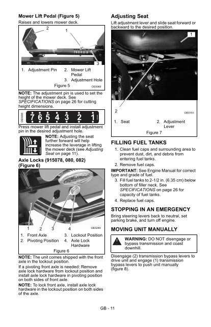
Mower Lift Pedal (Figure 5)<br />
Raises and lowers mower deck.<br />
2<br />
1<br />
Adjusting Seat<br />
Lift adjustment lever and slide seat forward or<br />
backward to the desired position.<br />
1<br />
3<br />
1. Adjustment Pin 2. Mower Lift<br />
Pedal<br />
3. Adjustment Hole<br />
Figure 5<br />
OE0060<br />
NOTE: The adjustment pin is used to set the<br />
height of the mower deck. See<br />
SPECIFICATIONS on page 26 for cutting<br />
height dimensions.<br />
OE0090<br />
765 4 3 2 1<br />
Press mower lift pedal and install adjustment<br />
pin in the desired adjustment hole.<br />
NOTE: Adjusting the seat<br />
further forward will help<br />
increase the leverage in lifting<br />
the mower deck (see Adjusting<br />
Seat on page 11).<br />
Axle Locks (915078, 080, 082)<br />
(Figure 6)<br />
08088400A<br />
1<br />
OE0240<br />
2 3 4<br />
1. Front Axle 3. Lockout Position<br />
2. Pivoting Position 4. Axle Lock<br />
Hardware<br />
Figure 6<br />
NOTE: The unit comes shipped with the front<br />
axle in the lockout position.<br />
If a pivoting front axle is needed: Remove<br />
axle lock hardware from lockout position and<br />
install axle lock hardware in pivoting position<br />
on both sides of front axle.<br />
NOTE: To lock front axle, install axle lock<br />
hardware in the lockout position on both sides<br />
of the axle.<br />
05304900<br />
2<br />
1. Seat 2. Adjustment<br />
Lever<br />
Figure 7<br />
FILLING FUEL TANKS<br />
1. Clean fuel caps and surrounding area to<br />
prevent dust, dirt, and debris from<br />
entering fuel tanks.<br />
2. Remove fuel caps.<br />
IMPORTANT: See Engine <strong>Manual</strong> for correct<br />
type and grade of fuel.<br />
3. Fill fuel tanks to 2-1/2 in. (6.35 cm) below<br />
bottom of filler neck. See<br />
SPECIFICATIONS on page 26 for<br />
capacity of fuel tanks.<br />
4. Replace fuel caps.<br />
STOPPING IN AN EMERGENCY<br />
Bring steering levers back to neutral, set<br />
parking brake, and turn off engine.<br />
MOVING UNIT MANUALLY<br />
OE0151<br />
WARNING: DO NOT disengage or<br />
bypass transmission and coast<br />
downhill.<br />
Disengage (2) transmission bypass levers to<br />
drive unit and engage (1) transmission<br />
bypass levers to push unit manually<br />
(figure 8).<br />
GB - 11