
You also want an ePaper? Increase the reach of your titles
YUMPU automatically turns print PDFs into web optimized ePapers that Google loves.
WARNING: AVOID INJURY. Read<br />
and understand the entire Safety<br />
section before proceeding.<br />
Tools Required<br />
• Adjustable wrench<br />
• Petroleum jelly or dielectric grease.<br />
Unpack Unit<br />
Remove unit and all other components from<br />
the shipping container. Engage transmission<br />
bypass lever (see on page 13). Push unit<br />
from container onto a level surface.<br />
Disengage transmission bypass lever.<br />
Connect Battery<br />
See Battery Removal and Installation on<br />
page 19 and perform steps 2 and 3 in the<br />
installation section.<br />
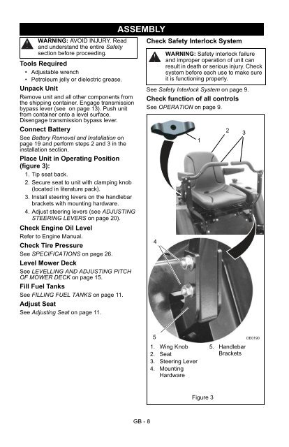
Place Unit in Operating Position<br />
(figure 3):<br />
1. Tip seat back.<br />
2. Secure seat to unit with clamping knob<br />
(located in literature pack).<br />
3. Install steering levers on the handlebar<br />
brackets with mounting hardware.<br />
4. Adjust steering levers (see ADJUSTING<br />
STEERING LEVERS on page 20).<br />
Check Engine Oil Level<br />
Refer to Engine <strong>Manual</strong>.<br />
Check Tire Pressure<br />
See SPECIFICATIONS on page 26.<br />
Level Mower Deck<br />
See LEVELLING AND ADJUSTING PITCH<br />
OF MOWER DECK on page 15.<br />
Fill Fuel Tanks<br />
See FILLING FUEL TANKS on page 11.<br />
Adjust Seat<br />
See Adjusting Seat on page 11.<br />
ASSEMBLY<br />
Check Safety Interlock System<br />
WARNING: Safety interlock failure<br />
and improper operation of unit can<br />
result in death or serious injury. Check<br />
system before each use to make sure<br />
it is functioning properly.<br />
See Safety Interlock System on page 9.<br />
Check function of all controls<br />
See OPERATION on page 9.<br />
4<br />
1<br />
2<br />
3<br />
5<br />
1. Wing Knob<br />
2. Seat<br />
3. Steering Lever<br />
4. Mounting<br />
Hardware<br />
5. Handlebar<br />
Brackets<br />
OE0190<br />
Figure 3<br />
GB - 8