hydraulic suppressors - Royal Hydraulics
hydraulic suppressors - Royal Hydraulics
hydraulic suppressors - Royal Hydraulics

Create successful ePaper yourself
Turn your PDF publications into a flip-book with our unique Google optimized e-Paper software.
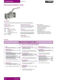
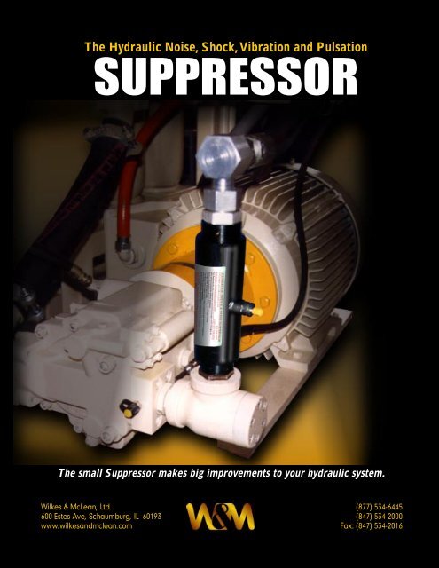
The Hydraulic Noise, Shock, Vibration and Pulsation<br />
SUPPRESSOR<br />
The small Suppressor makes big improvements to your <strong>hydraulic</strong> system.<br />
Wilkes & McLean, Ltd.<br />
600 Estes Ave, Schaumburg, IL 60193<br />
www.wilkesandmclean.com<br />
(877) 534-6445<br />
(847) 534-2000<br />
Fax: (847) 534-2016<br />
1
Page Index<br />
The Suppressor reduces noise, vibration and pulsation.<br />
What causes noise in a <strong>hydraulic</strong> system 3<br />
Why the Suppressor is so effective 4<br />
The Suppressor’s patented design 5<br />
Marine, mobile and industrial applications 6<br />
Multiple pump circuit applications 7<br />
How can the Suppressor save you money 8<br />
It’s easy to size and install a Suppressor 9<br />
Suppressor sizes, dimensions and models<br />
700 psi low pressure, high flow Suppressors 10<br />
700 psi low pressure, high flow Suppressors 11<br />
3000 psi Suppressors 12<br />
3000 psi Suppressors 13<br />
5000 psi Suppressors 14<br />
Stainless steel Suppressors 15<br />
BSP Thread, 210 bar and 350 bar Suppressors 16<br />
Accessories and how to charge a Suppressor<br />
Mounting clamps and spare parts 17<br />
Remote charging 18<br />
Charging a Suppressor 19<br />
How to select the right Suppressor<br />
First, locate your<br />
maximum system<br />
pressure in column 1.<br />
Second, locate your<br />
desired connection<br />
type in column 2.<br />
Third, locate the size<br />
of the connection in<br />
column 3.<br />
Fourth, use the brochure<br />
page # for the model<br />
number and dimensions<br />
1. System 2. Type of 3. Size of 4.<br />
Pressure Connection Connection Page #<br />
700 psi N.P.T. 1”, 1.25”, 1.5”, 2.0” 10<br />
Straight Thread 16, 20, 24, 32 10<br />
Flange 2.0”, 2.5”, 3.0” 11<br />
3000 psi N.P.T .375”, .5”, .75”, 1.0”, 1.25”, 1.5”, 2” 12<br />
Straight Thread 6, 8, 10, 12, 14, 16, 20, 24, 32 12<br />
Flange 12, 16, 20, 24, 32, 40, 48 13<br />
5000 psi Straight Thread 12, 14, 16, 20, 24 14<br />
Flange 12, 16, 20, 24, 32 14<br />
Stainless Steel<br />
3000 psi N.P.T. .75”, 1.0”, 1.25”, 1.5” 15<br />
Straight Thread 12, 14, 16, 20, 24 15<br />
Metric Connections<br />
210 bar B S P .375, .50, .75, 1.0, 1.25, 1.5, 2 16<br />
350 bar B S P .75, 1.0, 1.25, 1.5 16<br />
2
What causes noise<br />
in a <strong>hydraulic</strong><br />
system<br />
The Suppressor reduces noise, vibration & pulsation.<br />
Pump pressure and pump sizes have about equal<br />
effects on <strong>hydraulic</strong> noise levels. However the<br />
pump speed has about 300% greater affect on<br />
pump noise than either pressure or pump size. This<br />
is the reason some pump manufacturers recommend<br />
slower electric motor speeds. Fixed pumps<br />
are usually quieter then variable displacement<br />
pumps.<br />
Shown are two <strong>suppressors</strong> mounted on the front face of two<br />
pumps. Before the <strong>suppressors</strong> were added this was a noisy<br />
installation because the steel floor under the pumps radiated<br />
the noise.<br />
It is almost impossible to forecast how much additional<br />
sound the <strong>hydraulic</strong> lines and surrounding<br />
structure will radiate. This is why many power units<br />
are enclosed after they have been manufactured<br />
and installed. Slight adjustments to the nitrogen<br />
precharge of the Suppressor will vary the noise<br />
control. This is easier than wrapping the piping in<br />
sound absorbing tape, or enclosing the entire<br />
power unit as an afterthought.<br />
Pictured are two variable displacement pumps that operate at<br />
1800 rpm. The combination of two pumps operating at a high<br />
speed made this a noisy application until the two flange<br />
mounted Suppressors, identified by the green bands, were<br />
added to the pump outlets.<br />
Lab tests show that pump noise levels are increased<br />
by 2 to 3 dB(A) just by adding 12 feet of<br />
outlet and return lines. The lines do not generate<br />
noise; instead they radiate noise when they respond<br />
to pulsations or vibrations. The pump usually<br />
generates the pulsations and the vibrations are<br />
radiated by large flat machine surfaces.<br />
So not only do <strong>hydraulic</strong> lines radiate noise but also<br />
they frequently provide the primary path for propagating<br />
noise from the pump to components. This<br />
helps explain why many pump manufacturers have<br />
a very low dB(A) pump rating, but when the pump<br />
is installed on a power unit the sound rating is much<br />
higher.<br />
Notice the maze of piping in back of this suppressor. It would<br />
have been difficult for a designer to realize that piping would<br />
be there and that it carried the sound and vibrations to other<br />
parts of the circuit before the suppressor was installed.<br />
3
The Suppressor reduces noise, vibration & pulsation.<br />
Why is the Wilkes & McLean noise and<br />
<strong>hydraulic</strong> shock Suppressor so effective<br />
The Suppressor is an “in line” device that reduces<br />
the noise of any <strong>hydraulic</strong> power unit. It performs<br />
the same function for a <strong>hydraulic</strong> line as a muffler<br />
does on an automobile. It makes the unit quieter by<br />
absorbing the sound.<br />
The Suppressor offers a second advantage to a<br />
<strong>hydraulic</strong> system. It also reduces <strong>hydraulic</strong> pulsations<br />
and <strong>hydraulic</strong> shock. Hydraulic pulsations can<br />
cause pump wear and also cause leakage at tube<br />
or pipe connections.<br />
Because of the small size of the unit, the most<br />
popular size is only 8.25" long, it can easily be<br />
installed on any existing power unit. It comes in all<br />
pipe sizes; from 3/8" N.P.T. to 2" N.P.T., and all tube<br />
sizes; from .375” to 2.0". Flange connections are<br />
available in the larger sizes. The Suppressor is<br />
usually installed as close to the pump as possible. It<br />
can also be installed as close to any source of<br />
shock as possible.<br />
Every <strong>hydraulic</strong> application is different. Field tests<br />
have shown that the Suppressor will effectively<br />
reduce noise by up to 60%. The Suppressor will also<br />
reduce harmonic noise often present in dual pump<br />
circuits. The Suppressor will not reduce noise<br />
caused by the electric motor, pump coupling, or<br />
bearings.<br />
It is no longer necessary to build sound enclosures<br />
around power units to isolate noise because the<br />
power unit does not meet customer noise specifications.<br />
Under most circumstances the Wilkes &<br />
McLean Noise Suppressor will take those extra<br />
decibels out of the unit.<br />
Noise pollution is the hottest topic in the <strong>hydraulic</strong><br />
industry today. Automotive companies are reducing<br />
acceptable noise standards. The Wilkes &<br />
McLean Suppressor helps you meet those stringent<br />
new requirements.<br />
Multiple pumps cause more noise.<br />
Multiple pump circuits are a major<br />
cause of <strong>hydraulic</strong> noise. This photo<br />
shows two pumps mounted on top of<br />
each other in order to save floor space<br />
on a multimillion dollar yacht. The<br />
<strong>hydraulic</strong> pumps control the fin<br />
stabilizer systems for the yacht. In<br />
addition to soundproof mounting of the<br />
pumps and piping, it was still<br />
necessary to use the Suppressors in<br />
order to reduce sound levels to<br />
acceptable standards.<br />
Sometimes the quality of the sound is<br />
as disturbing as the elevated sound<br />
level. The sound quality can also be<br />
changed by adjusting the precharge<br />
of the Suppressor.<br />
4
The Suppressor reduces noise, vibration & pulsation.<br />
The Suppressor’s patented design is<br />
guaranteed to make any <strong>hydraulic</strong><br />
system quieter<br />
Suppressor cross section view<br />
Nitrogen<br />
Charging Valve<br />
•<br />
•<br />
• •<br />
Hydraulic<br />
Oil, red<br />
3 Baffle<br />
Chamber<br />
Diffuser Tube<br />
Nitrogen<br />
Charge, blue<br />
Bladder, black line<br />
How does the Hydraulic Noise and<br />
Shock Suppressor Work<br />
The <strong>hydraulic</strong> noise enters the Suppressor and goes<br />
through three different noise baffles or diffusers.<br />
These metal baffles are designed to convert 1/2"<br />
diameter holes to 1/32" diameter holes. The total<br />
radial distance through these baffles is only 1/4".<br />
After passing through these holes the noise then<br />
strikes the nitrogen charged rubber tube, or bladder.<br />
The bladder is usually charged with nitrogen<br />
to 50% to 60% of the <strong>hydraulic</strong> operating pressure.<br />
The 1/32" diameter holes are so small that the<br />
bladder cannot extrude into them. The bladder<br />
deflects each time it is hit by a pulsation. This slight<br />
deflection of the bladder reduces the shock and<br />
noise.<br />
The large bladder area and the short travel distance<br />
combine to absorb high frequency pulsations<br />
over 600 Hertz.<br />
Suppressor end view<br />
Outer<br />
Steel Tube<br />
Bladder<br />
Diffuser<br />
Tube<br />
Nitrogen<br />
Oil<br />
•<br />
•<br />
Nitrogen<br />
Charging Valve<br />
This artist's view of the Suppressor with the end removed<br />
illustrates the outer steel shell, the nitrogen charge (blue), the<br />
bladder (black), the oil (red) and the diffuser tube.<br />
5
The Suppressor reduces noise, vibration & pulsation.<br />
The Suppressor is<br />
used for industrial,<br />
mobile, and marine<br />
applications.<br />
Examples of marine applications<br />
The sound level for these two special cranes, the one on the<br />
right for lowering the remotely controlled vehicle into the water<br />
and the one on the left for controlling the tether, has been<br />
reduced so the two operators can easily talk to each other<br />
during operation.<br />
The following shipboard functions all had noise<br />
reductions due to the <strong>suppressors</strong>: deck cranes,<br />
special remote vehicle cranes, winches, steering,<br />
anchor windlass, and bow thrusters.<br />
America’s premier deep-sea research vessel is 36 meters long.<br />
It’s primary mission is to provide a stable platform for<br />
deploying, operating and recovering a tethered, remotely<br />
operated, deep sea vehicle which can dive to a depth of two<br />
miles.<br />
This vessel uses 16 Suppressors on every shipboard<br />
<strong>hydraulic</strong> function to reduce noise. The <strong>hydraulic</strong><br />
pump room has twelve different pumps in it. Some<br />
of the pumps are 5,000 psi operating at 1800 RPM.<br />
The pump<br />
room is a small<br />
all metal room<br />
and it radiated<br />
noise throughout<br />
the entire<br />
vessel. The<br />
<strong>suppressors</strong><br />
helped solve<br />
this problem.<br />
Ten Suppressors<br />
were added to<br />
the outlet of the<br />
pumps after it<br />
was decided that<br />
the noise level<br />
had to be<br />
reduced. (The<br />
Suppressors are<br />
identified by the<br />
green stripe.)<br />
6
The Suppressor reduces noise, vibration & pulsation.<br />
Flange mounted Suppressors in multiple<br />
pump circuits<br />
Multiple pumps are a major source of<br />
noise.<br />
Large multiple pump flows and large lines usually<br />
result in extreme noise levels. The noise level is<br />
most evident after the complete installation, when<br />
vibrations from multiple pumps resonate off each<br />
other, increasing the noise level. Some systems are<br />
so noisy they constitute a hearing hazard.<br />
The Suppressor reduces the noise, vibrations and<br />
pulsations in <strong>hydraulic</strong> systems. It is most effective<br />
when installed as close to the pump as possible.<br />
The Suppressor can even be installed after the<br />
original installation.<br />
These six Suppressors quieted multiple flow lines installed in<br />
an overhead configuration.<br />
Due to space configuration, these six Suppressors were<br />
mounted in the lines leading from the pumps.<br />
The Suppressor shown is a flange mounted Suppressor at the<br />
pump outlet.<br />
The original thinking on this installation was that the hoses would dampen the noise and vibrations. When<br />
that failed these three Suppressors were installed and the system was quieted.<br />
7
The Suppressor reduces noise, vibration & pulsation.<br />
How can the Suppressor save you money<br />
Every time you reduce pulsations you reduce noise,<br />
leakage, and component wear. Pump pulsations<br />
cause vibrations. Vibrations cause leakage. Hydraulic<br />
leakage is expensive to clean up. When the<br />
Suppressor stops the pulsations it stops the source<br />
of the vibrations and the leakage.<br />
“It is not how much the<br />
suppressor costs, but what it<br />
costs not to use it that counts.”<br />
Save money on new system designs.<br />
Power unit manufacturers can now design a system<br />
to operate at 1800 rpm and use a smaller less<br />
expensive pump and motor. With the Suppressor<br />
they have a quieter and less expensive unit than<br />
they would have had at 1200 rpm. In the past the<br />
noise and pulsations of the higher rpm restricted<br />
their use.<br />
Save money by mounting the suppressor<br />
on existing equipment.<br />
The new split flange Suppressor mounting makes it possible to<br />
break in an existing flange connection and insert the<br />
suppressor between the flanges. This makes it easy and fast to<br />
try the suppressor in any circuit that has a flange connection at<br />
the pump outlet.<br />
This photo shows the Suppressor mounted at the pump outlet.<br />
There are sensors mounted immediately before and after the<br />
suppressor leading to the oscilloscope. This is the method<br />
used to get the tracings shown below.<br />
235 psi<br />
420 psi<br />
The straight thread suppressor is easily added to a run of<br />
tubing. There were two tube joints at this location. One was<br />
easily replaced with a suppressor.<br />
5.55 MSEC, 180<br />
HZ<br />
➝<br />
➝<br />
75 psi<br />
25 psi<br />
40 psi<br />
12 psi<br />
The Suppressor reduces pulsations<br />
from a piston pump at 4000 psi at<br />
1800 rpm from 235 psi to 25 psi.<br />
The Suppressor reduces pulsations<br />
from a piston pump at 2000 psi at<br />
1800 rpm from 420 psi to 40 psi.<br />
The Suppressor reduces pulsations<br />
and noise from a pump running at<br />
750 psi at 1200 rpm from 75 psi to 12<br />
psi and noise from 85 dB to 77 dB.<br />
8
It’s easy to size and install a Suppressor<br />
Sizing is easy<br />
No complex sizing formulas. The Suppressor is sized<br />
to match your <strong>hydraulic</strong> line size. There is a Suppressor<br />
for every pipe and tube size from 3/8" to 3".<br />
Port Connections<br />
There are five types of <strong>hydraulic</strong> line connections<br />
for the Suppressor:<br />
1. The N.P.T. pipe port connection from 3/8" to 2"<br />
pipe.<br />
2. The S.A.E. port connection from 3/8" to 2" tubing.<br />
3. The Split Flange connection from 3/4" to 3".<br />
4. The Victaulic Flange connection from 2" to 3".<br />
5. BSP threads for Europe from 3/8 to 2.<br />
The Suppressor reduces noise, vibration & pulsation.<br />
Types of Suppressors<br />
There are four types of Suppressors:<br />
1. 700 psi rated (see pages 10 and 11 for<br />
dimensions)<br />
2. 3000 psi rated for oil operation (see pages 12<br />
and 13 for dimensions).<br />
3. 5000 psi for high pressure oil operation (see<br />
page 14 for sizes and dimensions).<br />
4. 3000 psi Stainless for water and chemical<br />
operation (see page 15 for sizes and<br />
dimensions).<br />
Bladder Materials<br />
The standard bladder material is high temperature<br />
HNBR -20° to +250°F. Viton, or EPR bladders, are<br />
also available for special applications.<br />
This double pump unit has a flange mounted Suppressor at<br />
one pump and a straight thread suppressor at the other pump<br />
(identified by green bands). The numerous Suppressor sizes<br />
and mountings make it easy to use in any circuit.<br />
How to Order<br />
Specify the Suppressor model number and the<br />
operating pressure. The line size and type of<br />
mounting will determine the model number as<br />
shown on the following pages. The operating<br />
pressure is needed if you want the Suppressor<br />
shipped with a nitrogen precharge.<br />
Suppressor Precharge<br />
The Suppressor can be shipped precharged with<br />
nitrogen to 50% of your system pressure. It is ready<br />
to install in your system. Tests have shown that this<br />
is the optimum precharge. Check precharge every<br />
6 months to maintain maximum efficiency.<br />
Mounting the Suppressor<br />
In order to reduce noise and pump pulsations the<br />
Suppressor should be mounted as close to the<br />
pump as possible. This stops the noise and pulsations<br />
before they get into the system and cause<br />
vibrations that increase noise levels and also cause<br />
leakage at fittings. If the Suppressor is used to<br />
reduce shock it should be mounted as close to the<br />
source of the shock as possible.<br />
This photo shows a typical installation. The Suppressor shown<br />
is only 8.25 inches long so it takes very little space.<br />
9
Suppressor sizes, dimensions and models<br />
700 psi low pressure, high flow<br />
Suppressors<br />
for N.P.T. Pipe Thread and Straight Thread Connections<br />
L<br />
H<br />
0.0<br />
D<br />
700 psi Suppressors for N.P.T. Ports<br />
MODEL N.P.T. FLOW DIMENSIONS WEIGHT<br />
NUMBER SIZE* G.P.M. Diameter Height Length LBS.<br />
15'/sec D H L<br />
WM 1138 - 1.0 1.00 68.9 3.845 1.75 8.875 21<br />
WM 1138 - 1.25 1.25 68.9 3.845 1.75 8.875 21<br />
WM 1138 - 1.5 1.50 68.9 3.845 1.75 8.875 21<br />
WM 11875 - 1.5 1.50 128 4.595 1.75 10.50 29<br />
WM 11875 - 2.0 2.00 128 4.595 1.75 10.50 29<br />
*For smaller size connections see the 3,000 psi line of Suppressors on page 12.<br />
700 psi Suppressors for SAE Ports<br />
MODEL SAE FLOW DIMENSIONS WEIGHT<br />
NUMBER SIZE* G.P.M. Diameter Height Length LBS.<br />
15'/sec D H L<br />
WM 1138 - 16 1.00 68.9 3.845 1.75 8.875 21<br />
WM 1138 - 20 1.25 68.9 3.845 1.75 8.875 21<br />
WM 1138 - 24 1.50 68.9 3.845 1.75 8.875 21<br />
WM 11875 - 2.0 2.00 128 4.595 1.75 8.875 29<br />
*For smaller size connections see the 3,000 psi line of Suppressors on page 12.<br />
10
Suppressor sizes, dimensions and models<br />
700 psi low pressure, high flow<br />
Suppressors<br />
for Victaulic Flange Connections<br />
L<br />
H<br />
0.0<br />
D<br />
700 psi Suppressors for Victaulic Flange Ports<br />
MODEL FLANGE FLOW DIMENSIONS WEIGHT<br />
NUMBER SIZE* G.P.M. Diameter Height Length LBS.<br />
15'/sec D H L<br />
WM 1138 - 2 SV 2.00 90 3.845 1.75 13.39 25<br />
WM 11875 - 2 SV 2.00 150 4.595 1.75 13.39 28<br />
WM 11875 - 2.5 SV 2.50 150 4.595 1.75 13.39 29<br />
WM 11875 - 3.0 SV 3.00 150 4.595 1.75 13.39 29<br />
Shown above is the 700 psi Suppressor with the flange on each end. The flange is used here because it has a lower pressure<br />
rating suitable for the 700 psi Suppressor. The Suppressor can be supplied with any combination of ports, such as SAE port on<br />
one end and a flange port on the opposite end. For higher pressure flange mounted Suppressors see pages 13 and 14.<br />
11
Suppressor sizes, dimensions and models<br />
3000 psi Suppressors<br />
for N.P.T. Pipe Thread and Straight Thread Connections<br />
➤<br />
➤<br />
➤<br />
H<br />
D<br />
Thread<br />
Size<br />
➤<br />
Thread<br />
Size<br />
➤<br />
➤<br />
➤<br />
L<br />
➤<br />
3000 psi Suppressors for N.P.T. Pipe Thread Connections<br />
MODEL N.P.T. FLOW FLOW DIMENSIONS WEIGHT<br />
NUMBER SIZE G.P.M. G.P.M. D H L LBS.<br />
15'/sec 20'/sec<br />
WM 3056 - .375 .375 11.3 15.1 2.5 1.75 6.875 6.5<br />
WM 3056 - .50 .500 11.3 15.1<br />
WM 3081 - .75 .750 24.2 32.1 2.625 1.75 8.13 8<br />
WM 3081 - 1.0 1.000 24.2 32.1<br />
WM 3138 - 1.0 1.000 68.9 91.9 4.125 1.75 8.875 20<br />
WM 3138 - 1.25 1.250 68.9 91.9<br />
WM 3138 - 1.5 1.500 68.9 91.9<br />
WM 31875 - 1.5 1.500 128.0 171.0 4.75 1.75 10.5 28.5<br />
WM 31875 - 2 2.000 128.0 171.0<br />
3000 psi Suppressors for Straight Thread Connections<br />
MODEL TUBE STRAIGHT FLOW FLOW DIMENSIONS WEIGHT<br />
NUMBER SIZE THREAD G.P.M. G.P.M. D H L LBS.<br />
15'/sec 20'/sec<br />
WM 3056 - 6 .375 9/16 - 18 11.3 15.1 2.5 1.75 6.875 6.5<br />
WM 3056 - 8 .500 3/4 - 16 11.3 15.1<br />
WM 3056 - 10 .625 7/8 - 14 11.3 15.1<br />
WM 3081 - 12 .750 1 1/16 - 12 24.1 32.1 2.625 1.75 8.13 8<br />
WM 3081 - 14 0.875 1 3/16 - 12 24.1 32.1<br />
WM 3081 - 16 1.000 1 5/16 - 12 24.1 32.1<br />
WM 3081 - 20 1.250 1 5/8 - 12 24.1 32.1<br />
WM 3138 - 16 1.000 1 5/16 - 12 68.9 91.9 4.125 1.75 8.875 20<br />
WM 3138 - 20 1.250 1 5/8 - 12 68.9 91.9<br />
WM 3138 - 24 1.500 1 7/8 - 12 68.9 91.9<br />
WM 31875 - 32 2.000 2 1/2 - 12 128.0 171.0 4.75 1.75 10.5 28.5<br />
Pressure drop in Suppressor is equal to pressure drop in one foot of tubing.<br />
To Order: specify model number and operating pressure.<br />
12
Suppressor sizes, dimensions and models<br />
3000 psi Suppressors<br />
for Code 61 and Code 62 Split Flange Mountings<br />
3000 psi Suppressors for Code 61 and Code 62 Split Flange<br />
MODEL FLANGE CODE 61 FLANGE DIMENSIONS CODE 62 FLANGE DIMENSIONS*<br />
NUMBER SIZE A B C E F A B C E F<br />
WM 3081 - 12 SF 0.75 1.75 .56 10.12 1.875 0.875 2.000 .75 10.620 2.000 0.938<br />
WM 3081 - 16 SF 1.00 1.75 .62 10.12 2.062 1.030 2.000 .94 10.620 2.250 1.094<br />
WM 3081 - 20 SF 1.25 2 .56 10.62 2.312 1.188 2.250 1.06 11.120 2.625 1.250<br />
WM 3138 - 20 SF 1.25 2.25 .56 13.12 2.312 1.188 2.250 1.06 13.125 2.625 1.250<br />
WM 3138 - 24 SF 1.50 2.25 .62 13.12 2.750 1.406 2.500 1.19 13.625 3.125 1.438<br />
WM 3138 - 32 SF 2.00 2.38 .62 13.38 3.062 1.688 2.620 1.44 13.875 3.812 1.750<br />
WM 31875 - 32 SF 2.00 2.38 .62 15.00 3.062 1.688 none none none none none<br />
WM 31875 - 40 SF** 2.50 2.875 .75 16.00 3.500 2.000 none none none none none<br />
WM 31875 - 48 SF*** 3.00 3.25 .88 16.75 4.188 2.438 none none none none none<br />
Split flanges are not included with the Suppressor. Flanges should be ordered as a separate item.<br />
*When ordering Suppressors with code 62 flanges add an X after model number. (Example: WM3138-20SFX)<br />
When using code 62 flanges do not exceed 3000 psi pressure rating of the Suppressor.<br />
**Max. pressure rating for this flange is 2500 psi.<br />
***Max. pressure rating for this flange is 2000 psi.<br />
The Suppressor ends are machined to mate with the standard SAE J518 - code 61 split flange.<br />
The Suppressor is shipped either with or without the<br />
split flanges. The Split Flange Suppressor is shipped<br />
with an “O” ring face on one flange end and a<br />
blank face on the other flange end. This is done so<br />
the Suppressor can be inserted between any<br />
existing flange connection. When ordering, specify<br />
if you want the split flanges shipped with the Sup-<br />
pressor. Specify the system operating pressure. The<br />
Suppressor can be shipped with a nitrogen precharge<br />
to 50% of the system pressure. Suppressors<br />
can also be ordered with any combination of ends,<br />
such as a split flange one end and a straight thread<br />
on the opposite end. When ordering special<br />
combinations, specify the type of connection for<br />
each end.<br />
13
Suppressor sizes, dimensions and models<br />
5000 psi Suppressors<br />
for Straight Thread and Split Flange Connections<br />
➤<br />
➤<br />
H<br />
➤<br />
D<br />
Thread<br />
Size<br />
➤<br />
Thread<br />
Size<br />
➤<br />
➤<br />
L<br />
5000 psi Suppressors for Straight Thread Connections<br />
➤<br />
MODEL FOR THREAD IN MAX. DIMENSIONS WEIGHT<br />
NUMBER TUBE SIZE SUPPRESSOR FLOW RATE D H L LBS.<br />
WM 5081 - 12 0.750 1 1/16 - 12 49 G.P.M. 3.50 1 8.13 16<br />
WM 5081 - 14 0.875 1 3/16 - 12<br />
WM 5081 - 16 1.000 1 5/16 - 12<br />
WM 5081 - 20 1.250 1 5/8 - 12<br />
WM 5138 - 16 1.000 1 5/16 - 12 90 G.P.M. 5.0 1 8.88 36<br />
WM 5138 - 20 1.250 1 5/8 - 12<br />
WM 5138 - 24 1.500 1 7/8 - 12<br />
➤<br />
5000 psi Suppressors for SAE Code 62 Split Flanges<br />
MODEL FLANGE DIMENSIONS<br />
NUMBER SIZE A B C E F<br />
WM 5081 - 12 SFX 0.75 2.00 .75 10.62 2.000 0.875<br />
WM 5081 - 16 SFX 1.00 2.00 .94 10.62 2.250 1.030<br />
WM 5081 - 20 SFX 1.25 2.25 .75 11.12 2.625 1.188<br />
WM 5138 - 20 SFX 1.25 2.25 .75 13.88 2.625 1.188<br />
WM 5138 - 24 SFX 1.50 2.50 .75 13.88 3.125 1.406<br />
WM 5138 - 32 SFX 2.00 2.62 .75 14.12 3.125 1.688<br />
The Suppressor is shipped either with<br />
or without the split flanges. When<br />
ordering, specify if you want the split<br />
flanges shipped with the Suppressor.<br />
The Split Flange Suppressor is<br />
shipped with an “O” ring face on one<br />
flange end and a blank face on the<br />
other flange end. This is done so the<br />
Suppressor can be inserted between<br />
any existing flange connection.<br />
Be sure to specify the system operating<br />
pressure because the Suppressor<br />
can be shipped with a nitrogen<br />
precharge to 50% of the system<br />
pressure. Suppressors can also be<br />
ordered with any combination of<br />
ends, such as a split flange one end<br />
and a straight thread on the opposite<br />
end. When ordering special combination<br />
of end connections, specify the<br />
type of connection for each end.<br />
14
Suppressor sizes, dimensions and models<br />
Stainless Steel Suppressors<br />
3000 psi for N.P.T. Pipe Thread and Straight Thread Connections<br />
➤<br />
H<br />
➤<br />
➤<br />
D<br />
Nitrogen<br />
Water or Chemical<br />
Tube Nickel<br />
Plated Inside<br />
and Out<br />
•<br />
"304" Stainless<br />
End Pieces<br />
•<br />
Thread<br />
Size<br />
➤<br />
➤<br />
➤<br />
Three "304" Stainless Baffle Chambers<br />
L<br />
➤<br />
Stainless Steel Suppressors 3000 psi for N.P.T. Pipe Thread Connections<br />
MODEL N.P.T. DIMENSIONS WEIGHT<br />
NUMBER SIZE D H L LBS.<br />
WM 3081 - .75 SS 0.75 2.625 1.75 8.13 8.5<br />
WM 3081 - 1.0 SS 1<br />
WM 3138 - 1.0 SS 1 4.125 1.75 8.875 20<br />
WM 3138 - 1.25 SS 1.25<br />
WM 3138 - 1.5 SS 1.5<br />
Stainless Steel Suppressors 3000 psi for Straight Thread Connections<br />
MODEL TUBE STRAIGHT DIMENSIONS WEIGHT<br />
NUMBER SIZE THREAD D H L LBS.<br />
WM 3081 - 12 SS 0.750 1 1/16 - 12 2.625 1.75 8.13 8.5<br />
WM 3081 - 14 SS 0.875 1 3/16 - 12<br />
WM 3081 - 16 SS 1.000 1 5/16 - 12<br />
WM 3081 - 20 SS 1.250 1 5/8 - 12<br />
WM 3138 - 16 SS 1.000 1 5/16 - 12 4.125 1.75 8.875 20<br />
WM 3138 - 20 SS 1.250 1 5/8 - 12<br />
WM 3138 - 24 SS 1.500 1 7/8 - 12<br />
All wetted parts are of 304 Stainless steel.<br />
The tubing is electroless nickel plated on the inside and out.<br />
The standard bladder material is Buna N. Special bladders are available, see page 7.<br />
15
Suppressor sizes, dimensions and models<br />
BSP Thread Connection Suppressors<br />
210 bar and 350 bar (metric dimensions)<br />
➤<br />
➤<br />
H<br />
➤<br />
D<br />
Thread<br />
Size<br />
➤<br />
Thread<br />
Size<br />
➤<br />
➤<br />
➤<br />
L<br />
➤<br />
BSP Thread Connections for 210 bar Suppressors<br />
MODEL BSP DIMENSIONS (metric) WEIGHT<br />
NUMBER THREAD SIZE D H L KG.<br />
WM 3056 - .375 BSP 3/8 63.5 44.45 174.62 3.1<br />
WM 3056 - .50 BSP 1/2<br />
WM 3081 - .75 BSP 3/4 66.66 44.45 206.5 3.6<br />
WM 3081 - 1.0 BSP 1<br />
WM 3081 - 1.25 BSP 1 1/4<br />
WM 3138 - 1.0 BSP 1 101.6 44.45 225.43 11.4<br />
WM 3138 - 1.25 BSP 1 1/4<br />
WM 3138 - 1.5 BSP 1 1/2<br />
WM 3187 - 1.5 BSP 1 1/2 120.65 44.45 266.7 14.1<br />
WM 3187 - 2 BSP 2<br />
BSP Thread Connections for 350 bar Suppressors<br />
Pressure drop in Suppressor is equal to pressure drop in one foot of tubing.<br />
To Order: specify model number and operating pressure.<br />
16<br />
MODEL BSP DIMENSIONS (metric) WEIGHT<br />
NUMBER THREAD SIZE D H L KG.<br />
WM 5081 - .75 BSP 3/4 85.85 25.4 206.5 6.8<br />
WM 5081 - 1.0 BSP 1<br />
WM 5081 - 1.25 BSP 1 1/4<br />
WM 5138 - 1.0 BSP 1 127 25.4 225.55 21.77<br />
WM 5138 - 1.25 BSP 1 1/4<br />
WM 5138 - 1.5 BSP 1 1/2
Accessories and how to charge<br />
Mounting Clamps<br />
Dimensions<br />
FOR SUPPRESSOR CLAMP NUMBER DIMENSIONS WIDTH<br />
MODEL NUMBER MODEL OF CLAMPS D A B C H<br />
NUMBER REQUIRED<br />
WM 1138 C 3138 1 4.00 7.00 6.30 5.03 2.41 1.25<br />
WM 11875 C 31875 2 4.75 7.00 6.30 5.70 2.78 1.25<br />
WM 3081 C 3081 1 2.62 5.00 3.94 3.75 1.66 1.25<br />
WM 3138 C 3138 1 4.00 7.00 6.30 5.03 2.41 1.25<br />
WM 31875 C 31875 2 4.75 7.00 6.30 5.70 2.78 1.25<br />
WM 5081 C 5081 1 3.38 5.00 3.94 4.48 2.10 1.25<br />
WM 5138 C 5138 2 5.00 7.00 6.30 5.92 2.91 1.25<br />
Self Adhesive Rubber Strip<br />
3/8-16 x 1-1/2<br />
Hex Head Bolt & Nut<br />
D<br />
.09<br />
.406<br />
C<br />
Clamp<br />
Model Number C 3081<br />
For Suppressor model<br />
number WM 3081.<br />
Clamp<br />
Model Number C 5138<br />
For Suppressor model<br />
number WM 5138.<br />
.12<br />
.37 x .5<br />
H<br />
B<br />
A<br />
Spare Parts<br />
To order specify spare part number and Suppressor model number.<br />
Spare parts are seldom required because there are no<br />
moving mechanical parts in the Suppressor, and the<br />
bladder bearly flexes to absorb pulsations.<br />
⎞<br />
⎟<br />
⎟<br />
⎠<br />
35<br />
40<br />
50<br />
60<br />
80<br />
PART PART ADDED<br />
NUMBER NAME INFORMATION<br />
10 Body Steel Body<br />
35 Valve Kit 35 Charging Valve<br />
30 “O” Ring (1) Tube Face "O" Ring<br />
40 “O” Rings (2) Tube O.D. "O" Ring<br />
50 “O” Rings (2) End Port "O" Ring<br />
60 End Port Specify Port Thread<br />
70 Difusser Only Sold as Unit<br />
80 Bladder Kit Specify Bladder Mat'l.<br />
Shipped with #30, #40,<br />
#50 “O” Rings.<br />
35<br />
60 50<br />
30 40 10<br />
80<br />
50<br />
40<br />
60<br />
10<br />
60<br />
50<br />
30<br />
40<br />
70<br />
• • • • • • • • • • • • • • • • • • • • •<br />
• • • • • • • • • • • • • • • • • • • • • •<br />
• • • • • • • • • • • • • • • • • • • • • • •<br />
• • • • • • • • • • • • • • • • • • • • • • • •<br />
• • • • • • • • • • • • • • • • • • • • • • • • •<br />
• • • • • • • • • • • • • • • • • • • • • • • • • •<br />
• • • • • • • • • • • • • • • • • • • • • • • • •<br />
• • • • • • • • • • • • • • • • • • • • • • • • • •<br />
• • • • • • • • • • • • • • • • • • • • • • • • •<br />
• • • • • • • • • • • • • • • • • • • • • • • •<br />
• • • • • • • • • • • • • • • • • • • • •<br />
• • • • • • • • • • • • • • • • • • • • • •<br />
70<br />
17
Accessories and how to charge<br />
Model Number RC1<br />
Remote Charging<br />
of Suppressors<br />
This remote charging device is a hose which extends<br />
the Suppressor charging valve outlet three<br />
feet. This allows access to Suppressors mounted in<br />
congested locations where charging is difficult. This<br />
device can also be used to establish a single<br />
charging or pre-charge check location for multiple<br />
Suppressors in a congested area.<br />
Precharge<br />
Checker<br />
Model Number CC<br />
In order to check the nitrogen precharge, and lose<br />
as little precharge as possible, the Precharge<br />
Checker should be used. The gauge is directly<br />
connected to the valve. When the valve is connected<br />
to the Suppressor the only nitrogen that<br />
escapes is the small amount needed to fill the<br />
gauge. This same Precharge Checker can be used<br />
for accumulators.<br />
Constant<br />
Monitoring of<br />
Precharge<br />
Pressure<br />
This pressure monitor adapter provides<br />
constant monitoring of pre-charge pressure.<br />
This pressure gauge is inserted with an<br />
adapter between the charging valve and<br />
the Suppressor.<br />
Model Number A1<br />
18
In order to check the precharge it is necessary to<br />
have a charging valve (model SV1) and a gauge<br />
(G2.5). A hose (H 10) is also necessary if additional<br />
nitrogen is required.<br />
Accessories and how to charge<br />
Charging a Suppressor<br />
Gauge, G2.5<br />
1/4" N.P.T. port.<br />
Complete assembly:<br />
charging valve, gauge, & hose.<br />
SV1, G2.5, & H10.<br />
Charging Valve, SV1<br />
Charging and bleeder valves with steel<br />
manifold 1/4" hose and gauge ports.<br />
Charging valve thread size is .305-32 UNEF.<br />
Hose, H 10<br />
1/4" N.P.T. port & fitting for<br />
2000 P.S.I. nitrogen bottle.<br />
To check the Suppressor precharge:<br />
1. Remove the valve cover, #1, from the Suppressor<br />
valve.<br />
2. Thread the Schrader type valve into the valve<br />
block. Install a pressure gauge in one of the<br />
1/4" ports. The other 1/4" port, normally used for a<br />
hose connection, should be plugged.<br />
3. Thread the Schrader valve and block onto the<br />
Suppressor valve. Make sure all connections are<br />
tight.<br />
4. While holding the body hex, #3, in place with a<br />
wrench, turn the swivel hex, #2, counter clockwise<br />
approximately 4 1/2 turns to<br />
open the poppet, #4. You<br />
can now read the nitrogen<br />
charge on the pressure<br />
gauge.<br />
5. After reading the<br />
nitrogen charge, turn the<br />
swivel hex nut, #2,<br />
clockwise 4 1/2 turns.<br />
6. Torque to approximately<br />
50 to 70 in./lbs.<br />
7. Remove the Schrader<br />
valve block from the<br />
Suppressor.<br />
8. Install the valve cover<br />
on the Suppressor.<br />
➤<br />
➤<br />
➤<br />
Charging a Suppressor:<br />
1. Remove the valve cover, #1, from the Suppressor<br />
valve. While holding the assembly nut, #3, in place with<br />
a wrench, turn the swivel hex nut, #2, counterclockwise<br />
approximately 4 1/2 turns to open the poppet, #4.<br />
2. Connect the Schrader type charging valve to the<br />
Suppressor valve. Since the Suppressor valve does not<br />
have a core, there is no need to utilize the‘T’ handle on<br />
the Schrader valve.<br />
3. Connect one end of the charging hose to the<br />
Schrader valve block and the other end of the hose with<br />
the bronze P.O.L. fitting to the nitrogen bottle. Open the<br />
valve on the nitrogen bottle slowly and allow the<br />
pressure to build to the desired level.<br />
#1<br />
Valve Cover<br />
#2<br />
Swivel Hex<br />
➤<br />
#4<br />
#3<br />
Body<br />
Hex<br />
Poppet<br />
4. When you reach the required pressure<br />
level, usually 50% of operating pressure, close<br />
the valve on the nitrogen bottle.<br />
5. Turn the swivel hex nut on the Suppressor<br />
valve clockwise approximately 4 1/2 turns to<br />
close the valve poppet.<br />
6. When the poppet has seated, apply<br />
approximately 50 to 70 in./lbs. of torque<br />
7. Open the bleeder valve on the Schrader<br />
valve block to vent the gas in the charging<br />
hose.<br />
8. Remove the Schrader valve from the<br />
Suppressor.<br />
9. Install the valve cover on the Suppressor.<br />
19
The Hydraulic Noise, Shock, Vibration and Pulsation<br />
SUPPRESSOR<br />
The reason multiple pumps cause noise problems is because<br />
each pump has its own set of vibrations. Multiple vibrations<br />
cause a harmonic resonance which results in unexpected noise.<br />
The solution is to use a Suppressor at the outlet of each pump.<br />
Multiple pumps not only increase the noise decibel level, they can make the<br />
“quality of noise” more irritating.<br />
The Suppressor changes both sound level and quality.<br />
Wilkes & McLean, Ltd.<br />
600 Estes Ave, Schaumburg, IL 60193<br />
www.wilkesandmclean.com<br />
(877) 534-6445<br />
(847) 534-2000<br />
Fax: (847) 534-2016<br />
20