Elekta Neuromag® Site Planning Guide for MaxShield - Psychology
Elekta Neuromag® Site Planning Guide for MaxShield - Psychology
Elekta Neuromag® Site Planning Guide for MaxShield - Psychology

Create successful ePaper yourself
Turn your PDF publications into a flip-book with our unique Google optimized e-Paper software.
<strong>Elekta</strong> Neuromag<br />
<strong>Elekta</strong> Neuromag ®<br />
<strong>Site</strong> <strong>Planning</strong> <strong>Guide</strong> <strong>for</strong><br />
<strong>MaxShield</strong><br />
June 2006<br />
—DRAFT—
DRAFT<br />
NOTICE<br />
This document contains copyrighted and possibly confidential<br />
in<strong>for</strong>mation and is intended <strong>for</strong> the exclusive use of customers<br />
having <strong>Elekta</strong> Neuromag products and authorized representatives<br />
of <strong>Elekta</strong> Neuromag Oy. Disclosure to others or other use is<br />
strictly prohibited without the express written authorization of<br />
<strong>Elekta</strong> Neuromag Oy.<br />
<strong>Elekta</strong> Neuromag Oy reserves the right to make changes in the<br />
specifications or data shown herein at any time without notice or<br />
obligation. <strong>Elekta</strong> Neuromag Oy denies any responsibility <strong>for</strong><br />
damage to apparatus or persons due to improper use or service<br />
per<strong>for</strong>med by unauthorized persons. <strong>Elekta</strong> Neuromag Oy assumes<br />
no liability <strong>for</strong> damage and/or failure of equipment caused<br />
by faulty site preparation.<br />
REVISION HISTORY<br />
- 15.11.2004 Preliminary draft edition<br />
- 30.6.2006 First release (final draft <strong>for</strong> review)<br />
© Copyright <strong>Elekta</strong> Neuromag Oy, Helsinki, Finland<br />
Printed in Finland.<br />
All rights reserved. Reproduction in any <strong>for</strong>m without the written<br />
permission of <strong>Elekta</strong> Neuromag Oy is strictly prohibited.<br />
2 NM21643A
DRAFT<br />
1<br />
CONTENTS<br />
1. MAGNETIC REQUIREMENTS ............................................................................... 5<br />
1.1. Sources of magnetic interference...................................................... 5<br />
1.2. Measurement of magnetic interference ............................................. 5<br />
1.3. Residual magnetic field inside the magnetically shielded room ........... 6<br />
2. MAXSHIELD MAGNETICALLY SHIELDED ROOM CHARACTERISTICS ......................... 8<br />
2.1. Dimensions .................................................................................... 8<br />
2.2. Feedthroughs ................................................................................. 8<br />
2.3. Door .............................................................................................. 9<br />
2.4. Inside / outside décor , lights, and accessories ................................... 9<br />
3. CLIMATIC REQUIREMENTS ............................................................................... 10<br />
3.1. Room temperature in the shielded room, equipment area and operator<br />
area ............................................................................................. 10<br />
3.2. Relative humidity in the shielded room, equipment area and operator<br />
area ............................................................................................. 11<br />
4. POWER SUPPLY AND GROUNDING REQUIREMENTS ............................................ 12<br />
4.1. Power Requirements ..................................................................... 12<br />
4.2. Connection to the building’s power lines, power requirements .......... 13<br />
4.3. Grounding .................................................................................... 14<br />
5. VIBRATION CONSIDERATIONS.......................................................................... 15<br />
5.1. General Recommendations ............................................................ 15<br />
5.2. Recommendations <strong>for</strong> allowable vibration ...................................... 15<br />
5.3. Measurement of vibration.............................................................. 16<br />
6. BUILDING REQUIREMENTS .............................................................................. 17<br />
6.1. Floor space requirements and layout considerations ........................ 17<br />
6.2. Load distribution .......................................................................... 20<br />
6.3. Free ceiling height requirements .................................................... 21<br />
6.3. Exhaust vents................................................................................ 21<br />
6.4. Transportation and access during installation .................................. 21<br />
6.5. Dimensions of the main components of the MEG system ................... 22<br />
6.6. Other considerations ..................................................................... 22<br />
7. TELECOMMUNICATION FACILITIES ON SITE ........................................................ 23<br />
APPENDIX............................................................................................................. 24<br />
MEG-MRI layout considerations ...................................................... 24<br />
NM21643A 3
DRAFT<br />
4 NM21643A
DRAFT<br />
<strong>Elekta</strong> Neuromag® <strong>Site</strong> <strong>Planning</strong> <strong>Guide</strong> <strong>for</strong> <strong>MaxShield</strong><br />
1<br />
1. MAGNETIC REQUIREMENTS<br />
1.1. Sources of magnetic interference<br />
1.2. Measurement of magnetic interference<br />
A site survey must be conducted to define the location of the<br />
<strong>Elekta</strong> Neuromag® system. The goal is to find an environment in<br />
which the magnetic disturbances are at a level low enough to be<br />
effectively compensated <strong>for</strong> by the shielded room and the active<br />
compensation systems.<br />
Obvious sources of magnetic interference are elevators, electrical<br />
trans<strong>for</strong>mers, power cables, mechanical/plant rooms, cars, parking<br />
lots, subways, subway stations, trains, street cars, MRI and<br />
CT scanners, and linear accelerators. <strong>Elekta</strong> should be contacted<br />
if any doubt exists regarding the effects of magnetic interference<br />
sources.<br />
Large volume/area ferromagnetic objects, e.g. steel-covered doors,<br />
walls, floors, and furniture should not be located in the vicinity of<br />
the shielded room because they may intensify the interference fields<br />
and cause movement artefacts. If in doubt, contact <strong>Elekta</strong>.<br />
Magnetic interference can also be generated by mechanical vibrations<br />
if the sensors move in the remanent field inside the room.<br />
For detailed discussion see Chapter 5.<br />
The level of magnetic interference is defined by measuring at<br />
different times of the day the three components of the ambient<br />
magnetic field (= B amb<br />
) as functions of time, and calculating the<br />
corresponding spectra. A three-head flux gate connected to a<br />
spectrum analyzer is used <strong>for</strong> this purpose. The measurement is<br />
carried out by <strong>Elekta</strong> or by an employee of a vendor of magnetically<br />
shielded rooms.<br />
If an MRI or CT unit or related equipment (see 1.1. above) is in close<br />
vicinity of the measurement point, the measurements should be<br />
carried out both with the equipment on and with the equipment off.<br />
For measurement of vibration, see Chapter 5.<br />
NM21643A 5
DRAFT<br />
1 Magnetic requirements <strong>Elekta</strong> Neuromag® <strong>Site</strong> <strong>Planning</strong> <strong>Guide</strong> <strong>for</strong> <strong>MaxShield</strong><br />
1.3. Residual magnetic field inside the magnetically shielded room<br />
The spectral density of the residual magnetic field B res<br />
inside the<br />
shield is calculated in the following way:<br />
B res<br />
= B amb<br />
(f)/S(f),<br />
where<br />
B amb<br />
(f) = the spectral density of the ambient magnetic field<br />
at frequency f (from the site survey). Usually, all<br />
three orthogonal directions are treated separately.<br />
It is also common to consider the vector sum of<br />
the x-, y-, and z-components.<br />
S(f) = the combined attenuation factor of the<br />
magnetically shielded room (MSR) and active<br />
compensation systems at frequency f. Note: in<br />
general, the shielding factor depends also on the<br />
location inside the room and on the direction. For<br />
simplicity, however, an average value of all<br />
directions in the middle of the room is often used.<br />
At DC, the state of static magnetization of the shielded room<br />
normally determines the remanent DC-field B rem<br />
in the room. In<br />
such a case the remanent field can be reduced by proper demagnetization.<br />
To obtain optimum per<strong>for</strong>mance of the magnetometer channels,<br />
the value of B amb<br />
, as a function of frequency, and the spectral<br />
density of the remanent DC-field B rem<br />
should not exceed the<br />
following values:<br />
Ambient magnetic field outside, Spectral density:<br />
B amb<br />
≤ 100 nT/ Hz at 0.1 Hz<br />
B amb<br />
≤ 10 nT/ Hz at 1 Hz<br />
B amb<br />
≤ 1 nT/ Hz above 10 Hz<br />
Remanent DC-field inside:<br />
B rem<br />
≤ 50 nT<br />
During MEG-measurements, the magnetometer channels must<br />
not saturate. The residual peak-to-peak fluctuation B res<br />
(0) p-p<br />
at<br />
very low frequencies is given by<br />
B res<br />
(0) p-p<br />
= B amb<br />
(0) p-p<br />
/S(0),<br />
6 NM21643A
DRAFT<br />
<strong>Elekta</strong> Neuromag® <strong>Site</strong> <strong>Planning</strong> <strong>Guide</strong> <strong>for</strong> <strong>MaxShield</strong> Magnetic requirements 1 1<br />
where<br />
B amb<br />
(0) p-p<br />
= the p-p fluctuation of the ambient field at very low<br />
frequencies as determined from at least 30 min long<br />
DC-coupled recordings during site survey, and<br />
S(0) = the low frequency limiting value of S(f).<br />
To guarantee operation, B amb<br />
(0) p-p<br />
should not exceed<br />
P-P range of ambient field:<br />
B amb<br />
(0) p-p<br />
≤ 2 µT<br />
If the above limits are exceeded, additional shielding might be<br />
necessary.<br />
NM21643A 7
DRAFT<br />
<strong>Elekta</strong> Neuromag® <strong>Site</strong> <strong>Planning</strong> <strong>Guide</strong> <strong>for</strong> <strong>MaxShield</strong><br />
2<br />
2. MAXSHIELD MAGNETICALLY SHIELDED ROOM CHARACTERISTICS<br />
2.1. Dimensions<br />
2.2. Feedthroughs<br />
External floor space:<br />
External height:<br />
Door opening:<br />
Door swing radius:<br />
3.2 m × 4.2 m (without exterior finish)<br />
2.6 m<br />
1.0 m × 2.0 m<br />
1.3 m<br />
The following 6 holes <strong>for</strong> technical feedthroughs are required <strong>for</strong><br />
the basic system:<br />
• 2 × φ85 mm <strong>for</strong> filter unit (feedthrough type A)<br />
• φ85 mm <strong>for</strong> stimulus cabinet (feedthrough type A)<br />
• φ35 mm <strong>for</strong> measurement unit movement control (feedthrough<br />
type B)<br />
• φ35 mm <strong>for</strong> helium boil-off (feedthrough type B)<br />
• φ100 <strong>for</strong> helium safety vent (feedthrough type C)<br />
Additional holes :<br />
• φ100 mm feedthrough <strong>for</strong> visual stimulus projector, center<br />
height 1000 mm above MSR inner floor (feedthrough type<br />
D). The visual stimulus projector is available as an option.<br />
• φ60 mm feedthrough <strong>for</strong> the optional intercom loudspeaker<br />
(feedthrough type E)<br />
.• φ35 mm hole <strong>for</strong> the optional CCTV camera (feedthrough<br />
type B)<br />
• Two φ120 mm holes / rectangular openings <strong>for</strong> ventilation<br />
(feedthrough type F)<br />
• φ35 mm hole <strong>for</strong> the lighting<br />
• One or two φ50 mm additional feedthroughs can be optionally<br />
provided <strong>for</strong> medical gases and patient monitoring devices<br />
such as a pulse oximeter. Alternatively, these feedthroughs<br />
can be fitted to the stimulus cabinet.<br />
The optimum hole locations vary according to the site. For<br />
details, contact <strong>Elekta</strong> representative, see also Section 6.1.<br />
User-supplied TV monitoring (CCTV) systems are not recommended<br />
to avoid RF-leakage via the camera and its cables.<br />
8 NM21643A
DRAFT<br />
<strong>Elekta</strong> Neuromag® <strong>Site</strong> <strong>Planning</strong> <strong>Guide</strong> <strong>for</strong> <strong>MaxShield</strong> <strong>MaxShield</strong> shielded droom 1 2<br />
2.3. Door<br />
Doorstep:<br />
0.13 m. A ramp (approx. 1 m length, slope < 10°) is provided to<br />
ensure easy access <strong>for</strong> both the subjects during MEG-measurements<br />
and <strong>for</strong> the LHe storage container during a re-fill operation.<br />
Door mechanism:<br />
2.4. Inside / outside décor , lights, and accessories<br />
Mechanical, can be manually opened both from inside and<br />
outside. The door is provided with a stopper to limit the opening<br />
to approximately 90°. For possible door locations, see Sect. 6.1.<br />
Inside wall coverage<br />
Provided with light, sound-absorbing and electrically insulating<br />
material.<br />
Outside wall coverage<br />
Outside coverage is not provided as standard part as it normally<br />
needs to be matched with the style and look of the surroundings.<br />
A dry-wall made of light electrically insulating material and built<br />
on site after shielded room installation is recommended. The<br />
outside coverage must not be attached to the shielded room wall.<br />
Inside floor<br />
Provided with easy to clean laminate resistent to eventual minor<br />
leakage of condensation water from the He-cooled pipes inside<br />
the gantry.<br />
Loads on ceiling and walls<br />
Additional load to unsupported magnetic shield material must<br />
not be applied. Light objects can be attached to inside décor.<br />
Interior lighting<br />
Adjustable and dimmable halogen spots (DC operated)<br />
Accessories<br />
All accessories brought inside the room should be of nonmagnetic<br />
material. Large metallic conducting objects (area > 0.25 m 2 ) must<br />
be avoided.<br />
NM21643A 9
DRAFT<br />
<strong>Elekta</strong> Neuromag® <strong>Site</strong> <strong>Planning</strong> <strong>Guide</strong> <strong>for</strong> <strong>MaxShield</strong><br />
3<br />
3. CLIMATIC REQUIREMENTS<br />
Maintaining the specified environmental conditions is essential<br />
to ensure the stable functioning of the system. Note that the<br />
relative humidity requirements have to be taken into account<br />
simultaneously with the temperature.<br />
NOTE:<br />
During transportation and storage, the temperature of the <strong>Elekta</strong><br />
Neuromag MEG system must be between 0 – 40 ºC, and the<br />
relative humidity between 10 – 95 %, non-condensing.<br />
3.1. Room temperature in the shielded room, equipment area and operator area<br />
Excessively high room temperatures may cause overheating of<br />
the power components thus reducing component lifetimes.<br />
Requirement <strong>for</strong> the ambient temperature outside the shielded<br />
room including the equipment area and the operator area:<br />
T amb<br />
= 20 – 24 ºC.<br />
Approximate heat load in the equipment area is 2 kW and in the<br />
operator area 3 kW (not including stimulators). Exact heat load<br />
depends on system configuration. Refer to Section 4 <strong>for</strong> more<br />
in<strong>for</strong>mation on power consumption.<br />
Requirement <strong>for</strong> the air temperature inside the shielded room:<br />
T MSR<br />
= 20 – 28 ºC.<br />
Approximate heat load due to electronics inside the shielded<br />
room is 0.3 kW. Addtional heat is generated by the lights (0.2 kW<br />
at full brightness) and persons inside (0.1 kW per person). The<br />
heat transfer through the MSR wall depends on the wall covering,<br />
which effectively acts as thermal insulation. There<strong>for</strong>e, ventilation<br />
in the room should be designed to carry the heat away.<br />
NOTE:<br />
To maintain the temperature inside the shielded room below 28 ºC,<br />
cooling of the input air may be needed. The minimum capacity of<br />
the air input 30 liters/s, corresponding to temperature difference<br />
of 8 °C.<br />
10 NM21643A
DRAFT<br />
<strong>Elekta</strong> Neuromag® <strong>Site</strong> <strong>Planning</strong> <strong>Guide</strong> <strong>for</strong> <strong>MaxShield</strong> Climatic requirements 1 3<br />
3.2. Relative humidity in the shielded room, equipment area and operator area<br />
Excessive air humidity promotes oxidation of metals, can be<br />
detrimental to electric circuits and computers and increase leakage<br />
currents as well as may cause water to condense on the cold<br />
parts of the system. Low humidity in turn increases static electricity,<br />
which can interfere with the SQUID detectors and damage<br />
electronic circuits. It also causes discom<strong>for</strong>t to the users.<br />
Relative humidity limits:<br />
RH = 40% – 70%.<br />
To maintain the humidity within limits, humidification/dehumidication<br />
systems are normally necessary. Natural air humidity<br />
can vary substantially depending on local climate, from 10 % to<br />
over 90 %.<br />
NM21643A 11
DRAFT<br />
<strong>Elekta</strong> Neuromag® <strong>Site</strong> <strong>Planning</strong> <strong>Guide</strong> <strong>for</strong> <strong>MaxShield</strong><br />
4<br />
4. POWER SUPPLY AND GROUNDING REQUIREMENTS<br />
4.1. Power Requirements<br />
The power requirements of the system units are listed in Table 1.<br />
The applicable standard line voltages (RMS) are: 100, 115, 120,<br />
200, 215, 220, 230, and 240 V. The recommended voltages are 200,<br />
230, and 240 V. The nominal line frequency should be 50 or 60 Hz.<br />
Table 1. Power consumption of system units.<br />
The total consumption depends on system configuration.<br />
U nit<br />
P ower [W]<br />
Appar.<br />
[VA]<br />
Notes<br />
Main<br />
electronics cabinet<br />
1700/1900<br />
1800/2000<br />
64 ch EEG / 128 ch EEG<br />
Lifting<br />
unit<br />
10/750<br />
20/1200<br />
Idle/working (20 s / run)<br />
3-D digitizer<br />
40<br />
60<br />
Acq.<br />
workstation, 2 TFT monitors (typ.) 400<br />
Anal.<br />
workstation, 2 TFT monitors (typ.) 400<br />
Trigger<br />
I/O unit (2 pcs, total)<br />
20<br />
Voice<br />
intercom (typ.)<br />
10<br />
CCTV video monitoring (typ.)<br />
50<br />
Finger<br />
response pad<br />
10<br />
DAT drive (typ.)<br />
100<br />
MOD drive (typ.)<br />
100<br />
Color<br />
printer (typ.)<br />
250<br />
/1650<br />
Norm./max.<br />
Monochrome<br />
printer (typ.)<br />
30/600<br />
Idle/printing<br />
Video<br />
projector (typ.)<br />
800<br />
Electrical<br />
stimulator (typ.)<br />
10<br />
Audiovisual<br />
stimulus system (typ.)<br />
200<br />
Feed-<strong>for</strong>ward<br />
active compensation<br />
200<br />
Shielded<br />
room lights<br />
200<br />
Note 1<br />
Note 2<br />
Stimulus cabinet not included as a unit since the consumption depends on the equipment used. Max 10 A.<br />
Ratings marked with "typ." are representative values only, actual values depend on the exact model used<br />
NOTE: Power requirements <strong>for</strong> lighting outside the shielded<br />
room, air conditioning, and general purpose outlets are not<br />
included.<br />
12 NM21643A
DRAFT<br />
<strong>Elekta</strong> Neuromag® <strong>Site</strong> <strong>Planning</strong> <strong>Guide</strong> <strong>for</strong> <strong>MaxShield</strong> Power supply and grounding 1 4<br />
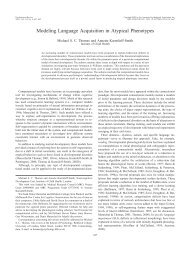
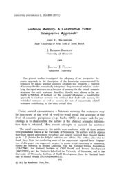
4.2. Connection to the building’s power lines, power requirements<br />
Separate power lines from the building’s main trans<strong>for</strong>mer and<br />
system isolation trans<strong>for</strong>mers are required, see Fig. 1. The isolation<br />
trans<strong>for</strong>mers (T 1<br />
and T 2<br />
) are provided by <strong>Elekta</strong>. They comply<br />
with the medical standards EN 60601-1 and EN 61558-2-15<br />
EN60742). The distance of the isolation trans<strong>for</strong>mers from the<br />
shielded room should normally be more than 3 m. For details,<br />
contact <strong>Elekta</strong>.<br />
At sites where the mains voltage is less than 230 V~ the lifting unit<br />
is connected to main using a portable step-up trans<strong>for</strong>mer provided<br />
with the system (plug connection).<br />
Power lines etc. cabling carrying substantial currents, power<br />
supplies, fluorescent lamps or other electric equipment should<br />
not be mounted on the shielded room walls or directly above the<br />
shielded room roof.<br />
MAINS<br />
L<br />
N<br />
PE<br />
S1<br />
S2<br />
F1<br />
L<br />
N<br />
PE<br />
L<br />
N<br />
PE<br />
Sockets <strong>for</strong><br />
workstations and<br />
other equipment<br />
(min. 10)<br />
System grounding point<br />
Filter Unit<br />
Grounding terminal in the<br />
trans<strong>for</strong>mer room<br />
S3<br />
100/115/120/<br />
200/230/240 V 230V<br />
T1<br />
F2 L<br />
N<br />
L1<br />
0<br />
L2<br />
F3<br />
S4<br />
F4<br />
Magnetically shielded room<br />
RF Filter Sockets<br />
L1<br />
S7<br />
L2<br />
PE<br />
S5<br />
0 S6<br />
N<br />
F7<br />
L = mains live<br />
L2<br />
N = mains neutral<br />
PE = protective earth (ground)<br />
L1 and L2 = isolated power terminals (symmetiric with respect to ground)<br />
Switches S7 and S8 are inside cabinets (max. 10A), supplied by <strong>Elekta</strong><br />
Secondary fuses (F3,F4,F6, F7) and switches (S4, S6) are optional<br />
F5<br />
L<br />
1:1<br />
T2<br />
L1<br />
F6<br />
Main electronics cabinet<br />
RF Filter Sockets<br />
L1<br />
S8<br />
L2<br />
PE<br />
Stimulus cabinet<br />
Figure 1. Connection to building’s power lines and grounding<br />
arrangements. The isolation trans<strong>for</strong>mers (T1–T2) and<br />
components inside cabniets are provided by <strong>Elekta</strong>.<br />
NM21643A 13
DRAFT<br />
4 Power supply and grounding <strong>Elekta</strong> Neuromag® <strong>Site</strong> <strong>Planning</strong> <strong>Guide</strong> <strong>for</strong> <strong>MaxShield</strong><br />
4.3. Grounding<br />
Proper grounding is essential in order to maintain shielding<br />
integrity. The guidelines listed below must be carefully followed.<br />
The magnetically shielded room (MSR) is grounded at one point<br />
only using a separate grounding cable connected to the common<br />
grounding terminal of the building trans<strong>for</strong>mer providing power<br />
to the <strong>Elekta</strong> Neuromag® system. The grounding cable should<br />
have a cross-section of 50 mm 2 or larger and it should be stranded<br />
(preferably fine-stranded) to ensure low inductance path to ground.<br />
The wire is connected to the M8 grounding bolt at the feedthrough<br />
filter unit during installation of the MEG system. The connection<br />
must be made in such a way that it can be disconnected when the<br />
isolation of the magnetically shielded room is measured. The<br />
isolation resistance between the disconneted shielded room and<br />
the end of the grounding cable must be more than 1 kΩ. The walls<br />
of the MSR must be electrically isolated from all building parts<br />
including the air conditioning ducts and helium exhaust pipes.<br />
All components of the electronics must be grounded to the same<br />
single point as the magnetically shielded room, see Figure 1.<br />
NOTE:<br />
A dedicated grounding electrode separate from the grounding<br />
terminal of the building trans<strong>for</strong>mer can be used but is not<br />
recommended.<br />
14 NM21643A
DRAFT<br />
<strong>Elekta</strong> Neuromag® <strong>Site</strong> <strong>Planning</strong> <strong>Guide</strong> <strong>for</strong> <strong>MaxShield</strong><br />
5<br />
5. VIBRATION CONSIDERATIONS<br />
5.1. General Recommendations<br />
Generally, the magnetically shielded room should be located at<br />
a place where low frequency vibrations are as small as possible.<br />
Thus, basements are preferred to upper floors.<br />
NOTE:<br />
Spring type suspension designs of the room are not recommended<br />
since they may cause low frequency oscillation.<br />
5.2. Recommendations <strong>for</strong> allowable vibration<br />
Magnetic interference signals due to mechanical vibrations are<br />
generated by the relative motion of the magnetic sensors with<br />
respect to the remanent field inside the room. A typical value of<br />
remanent field is ≤ 50 nT (see chapter 2.1.1). The magnetometers<br />
are more sensitive to the vibration than the gradiometers.<br />
General criteria <strong>for</strong> maximum allowable vibration observed in a<br />
site survey are difficult to define in practice. Vibration artefacts<br />
have often prominent peaks and if they happen to match with<br />
natural structural resonances of the room, the effect of building<br />
floor vibration may be augmented. Moreover, air pressure variations<br />
e.g. caused by ventilation can produce vibration artifacts.<br />
Magnetic artefact caused by vibration as such are relatively<br />
uni<strong>for</strong>m and is thus they are effectively reduced by software noise<br />
reduction based on spatial filtering like signal space projection<br />
and MaxFilter.<br />
The spectral density of the magnetic interference signal B vibr<br />
in a<br />
magnetometer channel due vibration is given by<br />
B vibr<br />
(f) ≤ X(f) B rem<br />
/ L 1<br />
,<br />
where<br />
X(f) = displacement spectrum of the magnetometer in the<br />
units of m/ Hz<br />
B rem<br />
L 1<br />
= remanent field inside the MSR (≤ 50 nT)<br />
= Characteristic length associated with the first<br />
gradient of the remanent magnetic field, typically<br />
L 1<br />
= 10 m.<br />
NM21643A 15
DRAFT<br />
5 Vibration considerations <strong>Elekta</strong> Neuromag® <strong>Site</strong> <strong>Planning</strong> <strong>Guide</strong> <strong>for</strong> <strong>MaxShield</strong><br />
5.3. Measurement of vibration<br />
The following conservative recommendations <strong>for</strong> the spectral<br />
density of the displacement spectrum at the site of the shielded<br />
room X amb<br />
are based on an assumption that disturbance due to<br />
vibrations is not seen in the magnetometer output spectrum when<br />
noise reduction techniques are not used.<br />
Displacement, Spectral Density (conservative recommendation)<br />
X amb<br />
≤ 20 µm/ Hz at 0.1 to 1 Hz<br />
X amb<br />
≤ 2 µm/ Hz at 1 to 10Hz<br />
X amb<br />
≤ 1 µm/ Hz above 10 Hz<br />
In case the readout of the vibration analyzer is in units of velocity,<br />
V amb<br />
, the corresponding criteria are:<br />
Velocity, Spectral Density (conservative recommendation)<br />
V amb<br />
≤ 12 (µm/s)/ Hz at 0.1 to 1 Hz<br />
V amb<br />
≤ 12 (µm/s)/ Hz at 1 to 10Hz<br />
V amb<br />
≤ 60 (µm/s)/ Hz ) at 10 Hz<br />
With proper signal-space noise reduction or by application of<br />
MaxFilter these values can be relaxed considerably. Thus<br />
exceeding these limits, especially only at certain frequencies, is<br />
not necessarily detrimental.<br />
The level of vibration is defined by measuring at different times<br />
of the day the displacement or velocity as functions of time, and<br />
calculating the corresponding spectra. If obvious sources of vibrational<br />
interference are in close vicinity of the measurement point, the<br />
measurements should be carried out both with the equipment on and<br />
with the equipment off.<br />
16 NM21643A
DRAFT<br />
<strong>Elekta</strong> Neuromag® <strong>Site</strong> <strong>Planning</strong> <strong>Guide</strong> <strong>for</strong> <strong>MaxShield</strong><br />
6<br />
6. BUILDING REQUIREMENTS<br />
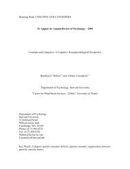
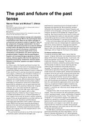
6.1. Floor space requirements and layout considerations<br />
The minimum floor space requirement <strong>for</strong> the complete system<br />
is about 40 m 2 . Anyhow, it is recommended, if possible, to<br />
reserve an area of 60–70 m 2 to ensure optimal conditions to<br />
operate the system from both operator’s and patient’s/subject’s<br />
point of view. Examples of site layouts are shown in Figs. 2 and<br />
3. For other possibilities, contact <strong>Elekta</strong> representative. See also<br />
discussion below.<br />
Outer dimensions of a <strong>MaxShield</strong> shielded room are given in<br />
chapter 2. The exact dimension will depend on the exterior<br />
finish.<br />
9000<br />
Isolation<br />
trans<strong>for</strong>mers<br />
Storage <strong>for</strong><br />
liquid Helium<br />
etc.<br />
Printer<br />
Analysis<br />
PC<br />
MEG Equipment area<br />
Electr.<br />
cabinet<br />
Feedthrough<br />
Lifting<br />
unit<br />
filter<br />
1500<br />
PC<br />
Acquisition<br />
Stimulus control<br />
Stimulus<br />
cabinet<br />
6500<br />
Ramp<br />
HPI chair<br />
Patient preparation<br />
and head digitization<br />
MSR<br />
equipment<br />
area<br />
Video<br />
projector<br />
Figure 2. Example layout of a large <strong>Elekta</strong> Neuromag® site. The<br />
office furniture, PCs, peripherals, stimulation equipment, and<br />
liquid Helium containers shown <strong>for</strong> illustrational purposes in the<br />
figure are not part of the standard system. Another example<br />
layout <strong>for</strong> a smaller site is shown in Fig. 3.<br />
NM21643A 17
DRAFT<br />
6 Building requirements <strong>Elekta</strong> Neuromag® <strong>Site</strong> <strong>Planning</strong> <strong>Guide</strong> <strong>for</strong> <strong>MaxShield</strong><br />
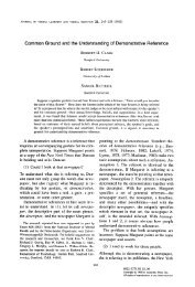
The door can be either on the shorter or on the longer side in any<br />
corner, subject to the following constraints:<br />
• distance from nearest outside corner to free opening is approx.<br />
0.5 m, depending on exterior finish thickness (see Fig.<br />
4)<br />
• handedness of the door is selectable<br />
• the door opening should be as far from the sensor unit as<br />
possible.<br />
• there should be enough space in front of the shielded room<br />
door <strong>for</strong> the door to open, to position the ramp and transfer<br />
in and out the bed, chair, and and helium storage vessels etc.<br />
The electronics is preferably located at the shorter side of the<br />
room behind the sensor unit. If space does not permit, alternative<br />
locations are possible as illustrated in Fig. 5. The following<br />
constraints must, however, be met:<br />
• free access to the the feedthrough filter unit is needed from all<br />
three sides not facing the shielded room wall (min. 0.3 m<br />
space)<br />
• both front and back doors of the main electronics cabinet<br />
need to be accessed and opened<br />
7000<br />
Analysis<br />
Printer<br />
MEG Equipment area<br />
Electr.<br />
cabinet<br />
Feedthrough<br />
filter<br />
Lifting<br />
unit<br />
1500<br />
Isolation<br />
trans<strong>for</strong>mers<br />
Stimulus control<br />
Acquisition<br />
Stimulus<br />
cabinet<br />
6500<br />
Ramp<br />
Patient preparation<br />
and head digitization<br />
HPI chair<br />
Storage <strong>for</strong><br />
liquid Helium<br />
etc.<br />
Video<br />
projector<br />
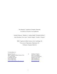
Figure 3. Example layout <strong>for</strong> a small <strong>Elekta</strong> Neuromag® site.<br />
18 NM21643A
DRAFT<br />
<strong>Elekta</strong> Neuromag® <strong>Site</strong> <strong>Planning</strong> <strong>Guide</strong> <strong>for</strong> <strong>MaxShield</strong> Building requirements 1 6<br />
0.5 m<br />
0.5 m<br />
Figure 4. Possible door locations. For further details, see text.<br />
800<br />
Feedthrough<br />
filter<br />
Lifting unit<br />
500<br />
Lifting unit<br />
Electr.<br />
cabinet<br />
Electr.<br />
cabinet<br />
Feedthrough<br />
filter<br />
Stimulus<br />
cabinet<br />
Stimulus<br />
cabinet<br />
Video<br />
projector<br />
Video<br />
projector<br />
VARIANT A<br />
VARIANT B<br />
Figure 5. Examples of alternative electronics locations. For further<br />
details, see text.<br />
NM21643A 19
DRAFT<br />
6 Building requirements <strong>Elekta</strong> Neuromag® <strong>Site</strong> <strong>Planning</strong> <strong>Guide</strong> <strong>for</strong> <strong>MaxShield</strong><br />
6.2. Load distribution<br />
• main electronics cabinet and feedthrough filter unit must be<br />
adjacent due to cable length restriction<br />
• exact feedthrough hole locations are subject to constraints<br />
due to support structures of the room. Feedthrough filter unit<br />
is centered with respect to the signal feedthrough holes<br />
• the lifting unit must be near the room corner in order to avoid<br />
too steep curves of the Bowden cable transmitting the movement<br />
• the cabinets and the lifting unit are not symmetric<br />
The <strong>MaxShield</strong> shielded room can even be directly located<br />
against a wall at two sides. Such configuration may, however,<br />
require special arrangements.<br />
An adequate space <strong>for</strong> liquid Helium storage container must be<br />
reserved. An easy access from the storage area to the shielded<br />
room should be ensured as well. The diameter of a typical 100-<br />
liter storage Dewar is 0.6–0.7 m and height 1.3–1.5 m.<br />
It is advisable to have an area <strong>for</strong> changing clothes and <strong>for</strong> waiting<br />
available in the near vivinity (not necessarily adjacent ot the MEG<br />
equipment area.<br />
Head digitization station should be near the data acquisition<br />
workstation or a dedicated additional terminal (PC). The analysis<br />
workstation does not need to have to be in the same area as the<br />
acquisition but it can also be remotely located.<br />
The total weight of the <strong>MaxShield</strong> shielded room with the<br />
system inside is typically 5000 kg. The weight is distributed<br />
approximately as follows:<br />
• Room floor and measurement unit: 1500 kg distributed<br />
evenly over the room area (12 m 2 )<br />
• Room walls and roof: 3500 kg distributed evenly on a 70 mm<br />
wide edge around the room area<br />
The room may be assembled on an underlayment (e.g. plywood)<br />
to distribute the load more evenly. In addition, the electronics<br />
cabinets need to be taken into account as approximately pointlike<br />
loads. For details, see Table 2.<br />
Conventionally, the load is expressed as the intensity of distributed<br />
load (average floor load). It is determined by calculating the<br />
intensity of a load evenly distributed over the whole external floor<br />
base plate which results in equal maximum deflection or maxi-<br />
20 NM21643A
DRAFT<br />
<strong>Elekta</strong> Neuromag® <strong>Site</strong> <strong>Planning</strong> <strong>Guide</strong> <strong>for</strong> <strong>MaxShield</strong> Building requirements 1 6<br />
6.3. Free ceiling height requirements<br />
6.3. Exhaust vents<br />
6.4. Transportation and access during installation<br />
mum principal bending moment as the load under investigation.<br />
Generally, the simple calculation of dividing the shielded room<br />
total mass by the shielded room area gives a too high value; <strong>for</strong><br />
proper determination the base plate properties need to be taken<br />
into account.<br />
The room can optionally be secured to the floor if required by<br />
local regulations (e.g. as a precaution <strong>for</strong> earthquakes).<br />
The installation of the <strong>MaxShield</strong> shielded room requires a<br />
clearance of 50 mm above the room exterior height.<br />
A free height of 1.50 m above the top opening of the liquid He<br />
storage containers should be available in the vicinity of the<br />
shielded room <strong>for</strong> the insertion of the LHe transfer siphon. If a<br />
siphon extention is used the length of the extension (0.22 m <strong>for</strong> the<br />
standard extension) should be added. The minimum area <strong>for</strong> this<br />
height is 1 m 2 . In operator area and equipment area there are no<br />
other special requirements.<br />
Provision must be made <strong>for</strong> a φ100 mm safety exhaust duct<br />
directly to the outside of the building.<br />
An area to unload the crates and an adequate access to the<br />
unloading area and from unloading area to the site must be<br />
provided during the installation of the system. The access route<br />
should not contain steps as many components are so heavy that<br />
<strong>for</strong>klifts (pallet jacks) must be used. Any door openings, corridors<br />
etc. should be wide and high enough that the crates and unloaded<br />
components can be transferred.<br />
All crates are to be transported in their original orientation whilst<br />
the components can be carried in any orientation (vertical/horisontal)<br />
which is convenient <strong>for</strong> access. The only exception is the<br />
MEG measurement unit which must always be kept in vertical<br />
orientation. Thus, a minimum height clearance of 2.00 m is<br />
required all the way, including all door openings.<br />
The largest crates <strong>for</strong> the LMSR are 3.2 m × 0.9 m × 0.9 m, 2.6 m<br />
× 1.8 m × 0.7 m, and 5.0 m × 0.3 m × 0.3 m, 7 crates total.<br />
Correspondingly, the largest crates <strong>for</strong> MEG components are 1.6<br />
m × 1.2 m × 2.3 m and 2.5 m × 0.9 m × 1.1 m (LxWxH), 7 crates<br />
total.<br />
NM21643A 21
DRAFT<br />
6 Building requirements <strong>Elekta</strong> Neuromag® <strong>Site</strong> <strong>Planning</strong> <strong>Guide</strong> <strong>for</strong> <strong>MaxShield</strong><br />
Largest single shielded room elements that need to be transported<br />
from the unloading area to site are 1.6 m × 0.3 m × 2.3 m and 2.4<br />
m × 0.6 m × 0.1 m, and largest MEG components are 1.0 m x 1.3<br />
m x 2.0 m and 0.6 m × 0.8 m × 2.1 m.<br />
6.5. Dimensions of the main components of the MEG system<br />
6.6. Other considerations<br />
The dimensions of the main components of the system are listed<br />
in Table 2.<br />
A water faucet and sink is recommended in the patient preparation<br />
are.<br />
When designing the MEG area local regulations must be taken<br />
into account. These may include building, electrical and HVAC<br />
regulations as well as and possible requirements <strong>for</strong> hospital<br />
environment and occupational health.<br />
A smoke detector should be installed in the ventilation exhaust<br />
duct to monitor the inside of the shielded room. Installation of a<br />
fire detector inside the room is not recommended to prevent RF<br />
leakage through the detector cabling.<br />
Table 2. The dimensions of the components of the <strong>Elekta</strong><br />
Neuromag® system.<br />
Unit<br />
Width<br />
(cm)<br />
Depth<br />
(cm)<br />
Height<br />
(cm)<br />
Weight<br />
(kg)<br />
Measurement<br />
unit (supine/upright) 96<br />
128/160<br />
198/223<br />
350<br />
Patient<br />
bed (bed surface/maximum) 75<br />
230<br />
60/76<br />
75<br />
Patient<br />
chair<br />
70<br />
135<br />
78<br />
80<br />
Filter<br />
unit (adjustable height)<br />
100<br />
40<br />
150-190<br />
150<br />
MEG electronics cabinet<br />
60<br />
80<br />
212<br />
250<br />
Stimulus<br />
electronics cabinet<br />
60<br />
80<br />
202<br />
100<br />
Data<br />
acquisition workstation (min./typ.) 44/70<br />
57/75<br />
68<br />
25<br />
Data<br />
analysis workstation (min./typ.) 44/70<br />
57/75<br />
68<br />
20<br />
Monitors<br />
(typical 19" TFT, four pcs.) 41<br />
20<br />
46<br />
4 x 9<br />
Gantry<br />
lifting unit<br />
37<br />
64<br />
37<br />
30<br />
HPI<br />
chair + digitizing unit<br />
54<br />
56<br />
98<br />
10<br />
Back-projection<br />
screen<br />
118<br />
33/<br />
6 186<br />
35<br />
22 NM21643A
DRAFT<br />
<strong>Elekta</strong> Neuromag® <strong>Site</strong> <strong>Planning</strong> <strong>Guide</strong> <strong>for</strong> <strong>MaxShield</strong><br />
7<br />
7. TELECOMMUNICATION FACILITIES ON SITE<br />
For software installation and upgrades, possible troubleshooting,<br />
and maintenance, the site should be equipped with a remote<br />
access over tcp/ip -connection or with an ISDN line. Proper data<br />
security precautions such as dedicated firewall setups etc. should,<br />
however, be implemented.The data connection is needed already<br />
during the installation, as well as an ordinary telephone line.<br />
Computers of the MEG system are connected to ethernet network<br />
with twisted pair (UTP, CAT 5) cable. The cabling and<br />
location <strong>for</strong> network switch should be ready be<strong>for</strong>e the installation<br />
starts. For best per<strong>for</strong>mance the network should be a separate<br />
subnet. Following in<strong>for</strong>mation is needed <strong>for</strong> installation: the<br />
intended IP addresses of all devices, the network mask, the IP<br />
address of the gateway to external networks, the domain name<br />
and the IP address of the domain name server.<br />
If an official registered network is unavailable, the network<br />
addresses can be selected from non-routed internal network<br />
addresses. For details contact <strong>Elekta</strong>.<br />
NM21643A 23
DRAFT<br />
<strong>Elekta</strong> Neuromag® <strong>Site</strong> <strong>Planning</strong> <strong>Guide</strong> <strong>for</strong> <strong>MaxShield</strong><br />
A<br />
APPENDIX<br />
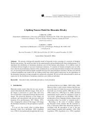
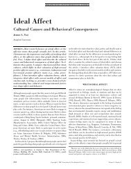
MEG-MRI layout considerations<br />
The following discussion illustrates the issues that have to be<br />
taken into account when locating the MEG unit and an MRI unit<br />
close to each other.<br />
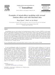
In an ideal situation the axis of the bore of the MRI unit should<br />
be parallel to the longer wall of the shielded room of the MEG<br />
unit. Additionally, the electronics cabinets of the MRI device<br />
should be as far away from the MEG unit as possible, as shown<br />
in Figs. A1 and A2. The purpose of these arrangements is to<br />
minimize, inside the magnetically shielded room, the effect of fast<br />
switching electromagnetic pulses of the MRI unit that are due to<br />
the gradient amplifiers. The permanent magnetic field generated<br />
by the MRI is not considered harmful to the operations of the<br />
MEG unit as long as we are beyond the 50-mT (0.5 G) line.<br />
Equipment area<br />
of the MEG unit<br />
RF-shield<br />
Magnetically<br />
shielded room<br />
MEG<br />
MRI<br />
Equipment area<br />
of the MRI unit<br />
Recommended minimum distance 10 meters<br />
Figure A1. The axis of the bore of t he MRI unit should preferably<br />
be parallel to the longer wall of the magnetically shielded room.<br />
If this is not possible, an alternative layout is shown in Fig. A2. It<br />
is recommended to locate the equipment area of the MRI unit as<br />
far away from the magnetically shielded room as possible.<br />
24 NM21643A
DRAFT<br />
<strong>Elekta</strong> Neuromag® <strong>Site</strong> <strong>Planning</strong> <strong>Guide</strong> <strong>for</strong> <strong>MaxShield</strong> Appendix 1 A<br />
Equipment area<br />
of the MEG unit<br />
Magnetically<br />
shielded room<br />
MEG<br />
Recommended minimum distance 10 meters<br />
MRI<br />
RF-shield<br />
Equipment area<br />
of the MRI unit<br />
Recommended minimum distance 10 meters<br />
Figure A2. Recommended layout if the axis of the MRI unit is not<br />
parallel to the longer wall of the magnetically shielded room. As<br />
in the previous layout above it is recommended to locate the<br />
equipment area of the MRI unit as far away from the magnetically<br />
shielded room as possible.<br />
NM21643A 25
<strong>Elekta</strong> Neuromag Oy<br />
P.O. Box 68<br />
FIN-00511 Helsinki, Finland<br />
Tel: +358 9 756 2400<br />
Fax: +358 9 756 24011<br />
E-mail: neuromag@elekta.com<br />
Web: www.elekta.com