Puffer Hubbard Lab Refrigerators Manual-FC-LR-RX - LABRepCo
Puffer Hubbard Lab Refrigerators Manual-FC-LR-RX - LABRepCo
Puffer Hubbard Lab Refrigerators Manual-FC-LR-RX - LABRepCo

Create successful ePaper yourself
Turn your PDF publications into a flip-book with our unique Google optimized e-Paper software.
Installation and Operation <strong>Manual</strong><br />
Thermo Scientific <strong>Puffer</strong> <strong>Hubbard</strong> ®<br />
<strong>Lab</strong>oratory <strong>Refrigerators</strong>
©<br />
2010 Thermo Fisher Scientific. All rights reserved.<br />
“Suva ® ” is a registered trademark of DuPont.<br />
All other trademarks are the property of Thermo Fisher Scientific Inc. and<br />
its subsidiaries.
Thermo Scientific <strong>Puffer</strong> <strong>Hubbard</strong> <strong>Lab</strong>oratory <strong>Refrigerators</strong><br />
Installation and Operation<br />
Table of Contents<br />
1 Introduction. . . . . . . . . . . . . . . . . . . . . . . . . . . . . . . . . . . . . . . . . . . . . . . . . . . . . . . . . . . . . . . . . . . . . . . 1<br />
2 Safety Precautions . . . . . . . . . . . . . . . . . . . . . . . . . . . . . . . . . . . . . . . . . . . . . . . . . . . . . . . . . . . . . . . . . 1<br />
3 Pre-Installation . . . . . . . . . . . . . . . . . . . . . . . . . . . . . . . . . . . . . . . . . . . . . . . . . . . . . . . . . . . . . . . . . . . . 1<br />
3.1 Unpacking. . . . . . . . . . . . . . . . . . . . . . . . . . . . . . . . . . . . . . . . . . . . . . . . . . . . . . . . . . . . . . . . . . . . . . . . . . . . . .1<br />
4 Installation. . . . . . . . . . . . . . . . . . . . . . . . . . . . . . . . . . . . . . . . . . . . . . . . . . . . . . . . . . . . . . . . . . . . . . . . 2<br />
4.1 Location . . . . . . . . . . . . . . . . . . . . . . . . . . . . . . . . . . . . . . . . . . . . . . . . . . . . . . . . . . . . . . . . . . . . . . . . . . . . . . .2<br />
4.2 Wiring . . . . . . . . . . . . . . . . . . . . . . . . . . . . . . . . . . . . . . . . . . . . . . . . . . . . . . . . . . . . . . . . . . . . . . . . . . . . . . . . .2<br />
4.3 Leveling . . . . . . . . . . . . . . . . . . . . . . . . . . . . . . . . . . . . . . . . . . . . . . . . . . . . . . . . . . . . . . . . . . . . . . . . . . . . . . .2<br />
4.4 Door Seal . . . . . . . . . . . . . . . . . . . . . . . . . . . . . . . . . . . . . . . . . . . . . . . . . . . . . . . . . . . . . . . . . . . . . . . . . . . . . .2<br />
4.5 Door Operation. . . . . . . . . . . . . . . . . . . . . . . . . . . . . . . . . . . . . . . . . . . . . . . . . . . . . . . . . . . . . . . . . . . . . . . . . .2<br />
4.5.1 Adjustable Hinged Glass Doors (Undercounter Models Only) . . . . . . . . . . . . . . . . . . . . . . . . . . . . . . . .2<br />
4.5.2 Sliding Glass Doors . . . . . . . . . . . . . . . . . . . . . . . . . . . . . . . . . . . . . . . . . . . . . . . . . . . . . . . . . . . . . . . .3<br />
4.6 Final Checks. . . . . . . . . . . . . . . . . . . . . . . . . . . . . . . . . . . . . . . . . . . . . . . . . . . . . . . . . . . . . . . . . . . . . . . . . . . .3<br />
5 Shelves and Drawer Slides . . . . . . . . . . . . . . . . . . . . . . . . . . . . . . . . . . . . . . . . . . . . . . . . . . . . . . . . . . 3<br />
6 Control Panel . . . . . . . . . . . . . . . . . . . . . . . . . . . . . . . . . . . . . . . . . . . . . . . . . . . . . . . . . . . . . . . . . . . . . 4<br />
6.1 Control Panel Features . . . . . . . . . . . . . . . . . . . . . . . . . . . . . . . . . . . . . . . . . . . . . . . . . . . . . . . . . . . . . . . . . . . .4<br />
6.2 Display Functions . . . . . . . . . . . . . . . . . . . . . . . . . . . . . . . . . . . . . . . . . . . . . . . . . . . . . . . . . . . . . . . . . . . . . . . .5<br />
6.3 Alarm Setpoints . . . . . . . . . . . . . . . . . . . . . . . . . . . . . . . . . . . . . . . . . . . . . . . . . . . . . . . . . . . . . . . . . . . . . . . . .5<br />
6.4 Service Mode Parameters . . . . . . . . . . . . . . . . . . . . . . . . . . . . . . . . . . . . . . . . . . . . . . . . . . . . . . . . . . . . . . . . .5<br />
7 Operation. . . . . . . . . . . . . . . . . . . . . . . . . . . . . . . . . . . . . . . . . . . . . . . . . . . . . . . . . . . . . . . . . . . . . . . . . 6<br />
7.1 Start Up . . . . . . . . . . . . . . . . . . . . . . . . . . . . . . . . . . . . . . . . . . . . . . . . . . . . . . . . . . . . . . . . . . . . . . . . . . . . . . .6<br />
7.2 Product Loading Guidelines . . . . . . . . . . . . . . . . . . . . . . . . . . . . . . . . . . . . . . . . . . . . . . . . . . . . . . . . . . . . . . . .6<br />
7.3 Automatic Defrost . . . . . . . . . . . . . . . . . . . . . . . . . . . . . . . . . . . . . . . . . . . . . . . . . . . . . . . . . . . . . . . . . . . . . . . .6<br />
7.4 Temperature Setpoint Control. . . . . . . . . . . . . . . . . . . . . . . . . . . . . . . . . . . . . . . . . . . . . . . . . . . . . . . . . . . . . . .6<br />
7.5 Interior Light Switch (Glass Door Units Only) . . . . . . . . . . . . . . . . . . . . . . . . . . . . . . . . . . . . . . . . . . . . . . . . . . .6<br />
8 Alarm Systems . . . . . . . . . . . . . . . . . . . . . . . . . . . . . . . . . . . . . . . . . . . . . . . . . . . . . . . . . . . . . . . . . . . . 7<br />
8.1 Operating the Alarm . . . . . . . . . . . . . . . . . . . . . . . . . . . . . . . . . . . . . . . . . . . . . . . . . . . . . . . . . . . . . . . . . . . . . .7<br />
8.2 Local and Remote Alarms . . . . . . . . . . . . . . . . . . . . . . . . . . . . . . . . . . . . . . . . . . . . . . . . . . . . . . . . . . . . . . . . .7<br />
8.3 Installing a Remote Alarm (Optional) . . . . . . . . . . . . . . . . . . . . . . . . . . . . . . . . . . . . . . . . . . . . . . . . . . . . . . . . .7<br />
8.4 Alarm Test . . . . . . . . . . . . . . . . . . . . . . . . . . . . . . . . . . . . . . . . . . . . . . . . . . . . . . . . . . . . . . . . . . . . . . . . . . . . .7<br />
8.4.1 Theory of Operation . . . . . . . . . . . . . . . . . . . . . . . . . . . . . . . . . . . . . . . . . . . . . . . . . . . . . . . . . . . . . . . .7<br />
8.4.2 Alarm Test Procedure . . . . . . . . . . . . . . . . . . . . . . . . . . . . . . . . . . . . . . . . . . . . . . . . . . . . . . . . . . . . . . .7<br />
i
9 Chart Recorders . . . . . . . . . . . . . . . . . . . . . . . . . . . . . . . . . . . . . . . . . . . . . . . . . . . . . . . . . . . . . . . . . . . 8<br />
9.1 Set Up and Operation. . . . . . . . . . . . . . . . . . . . . . . . . . . . . . . . . . . . . . . . . . . . . . . . . . . . . . . . . . . . . . . . . . . . .8<br />
9.2 Power Supply . . . . . . . . . . . . . . . . . . . . . . . . . . . . . . . . . . . . . . . . . . . . . . . . . . . . . . . . . . . . . . . . . . . . . . . . . . .8<br />
9.3 Changing Chart Paper . . . . . . . . . . . . . . . . . . . . . . . . . . . . . . . . . . . . . . . . . . . . . . . . . . . . . . . . . . . . . . . . . . . .8<br />
9.4 Calibration Adjustment . . . . . . . . . . . . . . . . . . . . . . . . . . . . . . . . . . . . . . . . . . . . . . . . . . . . . . . . . . . . . . . . . . . .8<br />
10 Maintenance . . . . . . . . . . . . . . . . . . . . . . . . . . . . . . . . . . . . . . . . . . . . . . . . . . . . . . . . . . . . . . . . . . . . . . 9<br />
10.1 Cleaning the Drawers and Cabinet Interior. . . . . . . . . . . . . . . . . . . . . . . . . . . . . . . . . . . . . . . . . . . . . . . . . . . . .9<br />
10.2 Removing the Drawers . . . . . . . . . . . . . . . . . . . . . . . . . . . . . . . . . . . . . . . . . . . . . . . . . . . . . . . . . . . . . . . . . . . .9<br />
10.3 Reinstalling the Drawers. . . . . . . . . . . . . . . . . . . . . . . . . . . . . . . . . . . . . . . . . . . . . . . . . . . . . . . . . . . . . . . . . . .9<br />
10.4 Cleaning the Condenser. . . . . . . . . . . . . . . . . . . . . . . . . . . . . . . . . . . . . . . . . . . . . . . . . . . . . . . . . . . . . . . . . . .9<br />
11 Troubleshooting . . . . . . . . . . . . . . . . . . . . . . . . . . . . . . . . . . . . . . . . . . . . . . . . . . . . . . . . . . . . . . . . . . .10<br />
12 Accessories . . . . . . . . . . . . . . . . . . . . . . . . . . . . . . . . . . . . . . . . . . . . . . . . . . . . . . . . . . . . . . . . . . . . . .11<br />
ii
Thermo Scientific <strong>Puffer</strong> <strong>Hubbard</strong> <strong>Lab</strong>oratory <strong>Refrigerators</strong><br />
Installation and Operation<br />
1 Introduction<br />
This manual provides installation and operation instructions for<br />
laboratory refrigerators, including general purpose, pharmacy,<br />
and chromatography models.<br />
The control system, standard on all models, includes:<br />
• Key-operated power and alarm switch<br />
• Preset temperature setpoint (+4ºC)<br />
• Digital temperature display with 0.1ºC resolution<br />
• Graphic temperature display<br />
• Audible and visual power failure indicators<br />
• Alarm silence, ringback, and automatic reset functions<br />
• Pushbutton alarm test<br />
Other standard features include:<br />
• Keyed door locks<br />
• Remote alarm contacts<br />
• C<strong>FC</strong>-free refrigerant<br />
• C<strong>FC</strong>-free foamed in-place urethane insulation<br />
• Quiet, hermetically sealed refrigeration compressors<br />
Seven day chart recorders are available as optional accessories<br />
on all models. For descriptions of other options and accessories,<br />
refer to Section 12.<br />
2 Safety Precautions<br />
In this manual and on labels attached to this product, the words<br />
WARNING and CAUTION mean the following:<br />
• WARNING: a potentially hazardous situation which, if not<br />
avoided, could result in serious injury or death.<br />
• CAUTION: a potentially hazardous situation which, if not<br />
avoided, may result in minor or moderate injury or damage to<br />
the equipment.<br />
Before installing, using or maintaining this product, please be sure<br />
to read this manual and product warning labels carefully. Failure to<br />
follow these instructions may cause this product to malfunction,<br />
which could result in injury or damage.<br />
The following important safety precautions apply to this product:<br />
• Use this product only in the way described in the product<br />
literature and in this manual. Before using it, verify that this<br />
product is suitable for its intended use.<br />
• Do not modify system components, especially the controller.<br />
Use OEM exact replacement equipment or parts. Before use,<br />
confirm that the product has not been altered in any way.<br />
• Your unit must be properly grounded in conformity with<br />
national and local electrical codes. Never connect the unit to<br />
overloaded power sources.<br />
• Disconnect the unit from all power sources before cleaning,<br />
troubleshooting, or performing other maintenance on the<br />
product or its controls.<br />
3 Pre-Installation<br />
3.1 Unpacking<br />
At delivery, examine the exterior for physical damage while the<br />
carrier’s representative is present. If exterior damage is<br />
present, carefully unpack and inspect the unit and all<br />
accessories for damage.<br />
If there is no exterior damage, unpack and inspect the<br />
equipment within five days of delivery. If you find any damage,<br />
keep the packing materials and immediately report the damage<br />
to the carrier. Do not return goods without written<br />
authorization. When submitting a claim for shipping damage,<br />
request that the carrier inspect the shipping container and<br />
equipment.<br />
1
Thermo Scientific <strong>Puffer</strong> <strong>Hubbard</strong> <strong>Lab</strong>oratory <strong>Refrigerators</strong><br />
Installation and Operation<br />
4 Installation<br />
Do not exceed the electrical and temperature ratings.<br />
CAUTION! Improper operation of the equipment<br />
could result in dangerous conditions. To preclude<br />
hazard and minimize risk, follow all instructions and<br />
operate within design limits noted on the dataplate.<br />
4.1 Location<br />
Install the unit in a level area free from vibration with a minimum<br />
of 6 inches of space on the sides and rear and 12 inches at the top.<br />
Do not position the equipment in direct sunlight or near heating<br />
diffusers, radiators, or other sources of heat. The ambient<br />
temperature range at the location must be 59 to 90°F<br />
(15to32°C).<br />
4.2 Wiring<br />
CAUTION! Connect the equipment to the correct<br />
power source. Incorrect voltage can result in severe<br />
damage to the equipment.<br />
DANGER! For personal safety and trouble-free<br />
operation, this unit must be properly grounded before<br />
it is used. Failure to ground the equipment may cause<br />
personal injury or damage to the equipment. Always<br />
conform to the National Electrical Code and local<br />
codes. Do not connect unit to already overloaded<br />
power lines.<br />
Always connect the equipment to a dedicated (separate) circuit.<br />
Electrical codes require fuse or circuit breaker protection for<br />
branch circuit conductors. Use time delay fuses for #12 AWG<br />
circuits.<br />
Chromatography refrigerators are equipped with a duplex vaporproof<br />
interior outlet with a maximum of 4 amps per receptacle.<br />
The wiring schematic is attached to the back of the cabinet.<br />
4.3 Leveling<br />
It is important to make sure the unit is level. Use thin sheets of<br />
metal to level units equipped with casters.<br />
Undercounter models come with leveling feet installed, with<br />
casters provided in a bag inside the cabinet. The unit must be<br />
level. To level undercounter units, rotate the leveling screws,<br />
located under the front corners of the unit, until the unit is level.<br />
If the floor is seriously out of level, you may need to shim the<br />
corners with thin sheets of metal.<br />
4.4 Door Seal<br />
To check the door seal, complete the following steps:<br />
1. Open the door.<br />
2. Insert a strip of paper (a couple of inches wide) between the<br />
door gasket and the cabinet flange and close the door.<br />
3. Slowly pull the paper strip from the outside. You should feel<br />
some resistance.<br />
4. Repeat this test at 4-inch intervals around the door. If the<br />
door does not seal properly, replace the gasket.<br />
CAUTION! Door seal integrity is critical for<br />
refrigerators and freezers. A loose fitting gasket allows<br />
moist air to be drawn into the cabinet, resulting in<br />
quicker frost buildup on the evaporator coil, longer<br />
running time, poor temperature maintenance, and<br />
increased operation cost.<br />
4.5 Door Operation<br />
Solid doors and standard glass doors for models larger than the<br />
undercounter model stay open if opened 90 degrees. Door spring<br />
tension cannot be adjusted.<br />
If the self-closing doors do not work properly, make sure the unit<br />
is level.<br />
4.5.1 Adjustable Hinged Glass Doors (Undercounter<br />
Models Only)<br />
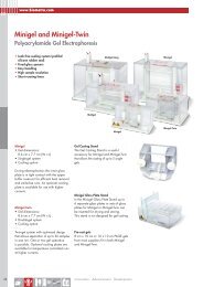
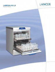
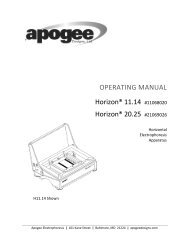
On undercounter models with hinged glass doors, you can use a<br />
regular screwdriver to adjust spring tension and center each door<br />
on its frame. The adjustment screws (“torque” for tension and<br />
“sag” for door placement) are located on the bottom hinge<br />
bracket (shown below in Figure 1).<br />
Hinged glass doors can be propped open with metal braces at the<br />
bottom hinges. Open the door 90 degrees or until you feel some<br />
resistance. Push the door open past the resistance and the metal<br />
braces engage. To close the door, push it toward the unit (past the<br />
resistance).<br />
Torque<br />
Sag<br />
Figure 1. Undercounter Hinge Bracket for Glass Door<br />
Adjustments<br />
CAUTION! Do not overtighten the tension as<br />
damage to the equipment can result.<br />
WARNING! Disconnect equipment from main power<br />
before attempting any maintenance to equipment or its<br />
controls.<br />
2
Thermo Scientific <strong>Puffer</strong> <strong>Hubbard</strong> <strong>Lab</strong>oratory <strong>Refrigerators</strong><br />
Installation and Operation<br />
4.5.2 Sliding Glass Doors<br />
45 ft 3 models have self-closing sliding glass doors.<br />
If the self-closing mechanism is not working properly, check to<br />
make sure that the unit is level.<br />
The sliding glass doors can be locked in the closed position,<br />
using the tubular key provided. To lock these doors:<br />
1. Locate the spring-loaded lock bolt at the bottom left of the<br />
right-hand door frame.<br />
2. The lock bolt has a small red dot. Insert the key over the bolt,<br />
lining up the dot with the ridge on the key.<br />
3. Rotate the lock bolt one half turn so that the dot is at the<br />
bottom of the bolt.<br />
4. Remove the key and push in the bolt to lock the door. The<br />
door can be locked only when the dot is in the bottom<br />
position.<br />
To unlock the doors:<br />
1. Insert the key over the bolt, lining up the dot with the ridge<br />
on the key.<br />
2. Rotate the lock bolt one half turn so that the dot moves back<br />
to the top of the bolt. The bolt will then spring back to the<br />
unlocked position.<br />
To hold the right-hand door open, slide the door to the left and<br />
use the hook located in the side of the left-hand door.<br />
4.6 Final Checks<br />
Before startup, complete the following steps:<br />
1. Make sure that the unit is free of all wood or cardboard<br />
shipping materials, both inside and outside.<br />
2. Verify that the unit is connected to a dedicated circuit.<br />
CAUTION! Connect the equipment to a separate,<br />
dedicated, power source. Power fluctuations can<br />
result in severe damage to the equipment.<br />
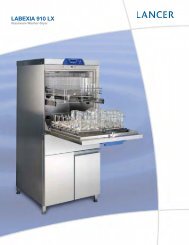
5 Shelves and Drawer Slides<br />
For safety in shipping, the shelves are packaged and secured<br />
inside the cabinet. Insert the shelf support hangers (included with<br />
the shelves) into the built-in pilasters (located on the inside walls<br />
of the cabinet interior) at the desired locations. Position the<br />
shelves on the flat supports (refer to Figure 2).<br />
Note:<br />
The number of shelves supplied per cabinet varies<br />
according to type of unit and size of cabinet.<br />
Figure 2. Shelf Support Hanger<br />
Drawer slides (standard for pharmacy refrigerators) are similar<br />
but have a small wire safety clip at the front pilaster which<br />
prevents the slides from falling when the drawers are removed.<br />
To change the position of the drawer slides, complete the<br />
following steps:<br />
1. Locate the safety clip.<br />
2. Slip your fingernail or a small screwdriver under the bottom<br />
of the wire clip and pry it out toward the inside of the<br />
refrigerator.<br />
3. Lift up the slide at front. The slide is free to move from the<br />
front pilaster.<br />
4. The drawer slide must be removed from the rear pilaster at<br />
approximately a 45 degree angle toward the center of the<br />
cabinet.<br />
5. Pull the slide toward the front of the cabinet.<br />
For more information on removing and reinstalling the drawers,<br />
refer to Section 10 on page 9.<br />
3
Thermo Scientific <strong>Puffer</strong> <strong>Hubbard</strong> <strong>Lab</strong>oratory <strong>Refrigerators</strong><br />
Installation and Operation<br />
6 Control Panel<br />
1 3 4 5<br />
9<br />
2<br />
10<br />
Key Switch<br />
6 7 8<br />
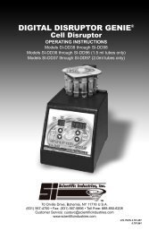
Figure 3. Refrigerator Control Panel<br />
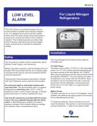
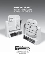
6.1 Control Panel Features<br />
The control panel is located on the top right side of your<br />
refrigerator. You can use the three pushbuttons (#5, #8, and #9 in<br />
Figure 3) to change the temperature display (#1) or to adjust<br />
temperature and alarm setpoints. The thermometer display (#2)<br />
provides a quick visual indicator of current cabinet temperature<br />
and alarm conditions.<br />
Before starting up your refrigerator, take some time to review the<br />
control panel functions:<br />
1. Main temperature display — during normal operation, shows<br />
cabinet temperature in degrees Celsius, as measured by the<br />
sensor inside the cabinet. You can use the buttons to display<br />
other values such as setpoints and extreme values. The<br />
number in the main display flashes when you are changing a<br />
value.<br />
2. Thermometer — shows cabinet temperature and alarm<br />
conditions. There are 10 horizontal bars: 9 are displayed<br />
during normal operation, the tenth (top) bar indicates a warm<br />
alarm condition. The number of bars illuminated indicates<br />
approximate cabinet temperature. Depending on alarm<br />
settings, 4 or 5 bars illuminated indicate that the cabinet is at<br />
setpoint.<br />
For example, suppose that the cabinet temperature setpoint is<br />
+4ºC and that the warm and cold alarm setpoints are 8ºC and<br />
0ºC. Then the number of bars illuminated indicates cabinet<br />
temperature as follows:<br />
bulb only 0ºC (cold alarm) 6 bars 4.8<br />
1 bar 0.8 7 bars 5.6<br />
2 bars 1.6 8 bars 6.4<br />
3 bars 2.4 9 bars 7.2<br />
4 bars 3.2 10 bars 8 (warm alarm)<br />
5 bars 4 (setpoint)<br />
When cabinet temperature exceeds the warm alarm setpoint,<br />
the top bar of the thermometer flashes. When temperature is<br />
lower than the cold alarm setpoint, the bulb flashes.<br />
When you are in programming mode (described in Table 2)<br />
the thermometer shows the setpoint value you are changing.<br />
3. Power failure — illuminated when the main power supply is<br />
interrupted. In this case the audible alarm also sounds.<br />
4. Service required —illuminated when the controller is in<br />
service programming mode or when simulated warm or cold<br />
alarm conditions are failing to occur during an alarm test.<br />
5. Increase — pushbutton used to increase setpoint values in<br />
programming mode and for various display functions.<br />
6. Door ajar — illuminated when the refrigerator door is open<br />
and the alarm is activated (key switch turned to the alarm<br />
position). (This feature is not available for 45 ft 3 sliding glass<br />
door models.)<br />
7. Battery low — illuminated when the backup battery is low.<br />
8. Decrease — pushbutton used to decrease setpoint values in<br />
programming mode and for various display functions.<br />
9. Scan — pushbutton used to change the main display and for<br />
various other functions.<br />
10. Audible alarm — illuminates during warm and cold alarm<br />
conditions.<br />
For full descriptions of display, programming, and service<br />
functions, refer to Tables 2, 3, and 4 on page 5.<br />
4
Thermo Scientific <strong>Puffer</strong> <strong>Hubbard</strong> <strong>Lab</strong>oratory <strong>Refrigerators</strong><br />
Installation and Operation<br />
6.2 Display Functions<br />
Table 2.<br />
Control Panel Display Functions (including optional alarm functions)<br />
Function Meaning Sequence Display<br />
Default display while refrigerator<br />
Normal operation<br />
— Temperature display, thermometer show cabinet temperature.<br />
is running<br />
Cold excursion<br />
Warm excursion<br />
Show coldest cabinet temperature<br />
since last startup or reset<br />
Show warmest cabinet temperature<br />
since last startup or reset<br />
Press<br />
Press<br />
Mute Silence audible alarm Press Scan<br />
Reset<br />
Alarm test<br />
Return to default display after<br />
excursion or alarm condition<br />
Test by simulating warm and cold<br />
alarm conditions; key switch must be<br />
in alarm mode<br />
Press and<br />
simultaneously, hold<br />
for five seconds<br />
Press and Scan<br />
simultaneously, hold<br />
for five seconds<br />
Thermometer, display show cold excursion while button is<br />
pressed.<br />
Thermometer, display show warm excursion while button is<br />
pressed.<br />
Thermometer, display show cabinet temperature, alarm icon<br />
continues to flash.<br />
Excursion values are reset; thermometer, display show cabinet<br />
temperature. Display blinks to confirm reset.<br />
Display and thermometer show simulated cabinet temperature,<br />
alarms flash and sound as appropriate. Alarms clear when test is<br />
completed.<br />
6.3 Alarm Setpoints<br />
To enter programming mode, press Scan, hold for 5 seconds, and release. The first two values displayed are the warm and cold alarm<br />
setpoints. Note that the alarm setpoints cannot be adjusted when the key switch is in the alarm position.<br />
Table 3. Alarm Setpoint Programming Functions (with Alarm Option Only)<br />
Function<br />
Adjust cold alarm setpoint<br />
Adjust warm alarm setpoint<br />
Programming Sequence<br />
Enter programming mode by pressing Scan and holding for 5 seconds. On release, the current cold alarm<br />
setpoint value flashes in the temperature display; use and to adjust it. The display automatically returns<br />
to normal operating mode 30 seconds after the last key entry or after scrolling through all available functions<br />
and parameters.<br />
Enter programming mode and press Scan repeatedly. The current warm alarm setpoint value then flashes in<br />
the temperature display; use and to adjust it. The display automatically returns to normal operating<br />
mode 30 seconds after the last key entry or after scrolling through all available functions and parameters.<br />
6.4 Service Mode Parameters<br />
When the key switch is not turned to third (alarm) position, you can access service parameters by entering programming mode and<br />
pressing Scan for an additional 5 seconds. On release of the button, the display will go blank, then display “SEr” with the service<br />
wrench icon illuminated. Then the firmware checksum (read-only) will be displayed for about 4 seconds. Pressing Scan repeatedly<br />
scrolls through the available service functions. While you are in service mode, the wrench icon is illuminated. For any flashing<br />
parameter you can use and to adjust the value.<br />
CAUTION! Resetting any of the following parameter values could adversely affect the performance of your refrigerator.<br />
These settings very rarely need to be changed for normal +4ºC operation. Be sure to call Service before making any<br />
adjustments to parameter values.<br />
Table 4.<br />
Programming Parameters<br />
Parameter Display Notes<br />
1. Offset Value<br />
Center air temperature calibration. Default value is 0 (maximum + or -<br />
2.9).<br />
2. Cut On Cut (2 sec.); On (2 sec.); then value<br />
Cabinet temperature at which compressor starts to cool down to<br />
setpoint. Default value is 6ºC.<br />
3. Differential dIF (2 sec.); then value<br />
Cut on – differential = temperature at which compressor stops after<br />
achieving cabinet temperature setpoint. Default value is 3.<br />
4. Defrost Interval dEF (2 sec.); Int (2 sec.); then value Range 1 to 12 hours; default value is 01.<br />
5. Defrost Duration dEF (2 sec.); dur (2 sec.); then value Range 5 to 30 minutes; default value is 15.<br />
6. Defrost HIgh-tempTermination dEF (2 sec.); HI (2 sec.); then value<br />
Temperature at evaporator at which defrost cycle terminates; default<br />
value is 4ºC.<br />
7. Short Cycle Delay SHO (2 sec.); Cyc (2 sec.); then value Range 0 to 15 minutes; default value is 0.<br />
8. Control Probe Temperature Cnt (2 sec.); Prb (2 sec.); then value Display only.<br />
9. Network address nEt (2 sec.); Adrt (2 sec.); then value Can only be modified by RS-485 communications software.<br />
10.Defrost Probe Temperature dEF (2 sec.); Prb (2 sec.); then value Display only.<br />
5
Thermo Scientific <strong>Puffer</strong> <strong>Hubbard</strong> <strong>Lab</strong>oratory <strong>Refrigerators</strong><br />
Installation and Operation<br />
7 Operation<br />
7.1 Start Up<br />
To start up the refrigerator, complete the following steps:<br />
1. Plug in the power cord.<br />
2. Insert the key in the switch and turn the power on.<br />
3. Rotate the power switch to the ALARM ON position when<br />
the temperature drops below the warm alarm setpoint.<br />
4. Allow the unit to reach operating temperature before loading<br />
it with any product. To stabilize the temperature profile,<br />
a 24-hour waiting period is recommended.<br />
5. After the unit has pulled down to the desired operating<br />
temperature, turn the three position key switch one turn<br />
further clockwise to the Alarm On position. (Space Saver<br />
units have a separate alarm key switch.)<br />
6. If you have a remote alarm, hook it up at this point (refer to<br />
Section 8.3 on page 7).<br />
7. Whether you have a built-in alarm or a customer-installed<br />
remote alarm, you should test it following the instructions in<br />
Section 8.4 on page 7. Alarm setpoints are factory pre-set for<br />
5.5 (warm) and 1.5°C (cold).<br />
7.2 Product Loading Guidelines<br />
When loading your refrigerator, take care to observe the<br />
following guidelines:<br />
• Never load the refrigerator beyond capacity.<br />
• Distribute the load as evenly as possible. Temperature<br />
uniformity depends on air circulation, which could be<br />
impeded if drawers are overfilled, particularly at the top of<br />
the cabinet.<br />
• For critical applications, be sure that the alarm systems are<br />
working and active before you load any product.<br />
7.4 Temperature Setpoint Control<br />
Your individual unit has been adjusted and factory tested to<br />
maintain a +4°C cabinet temperature. For laboratory<br />
refrigerators, cabinet temperature setpoint is a computed value<br />
based on the service parameters Cut On and Differential (see<br />
Table 4 on page 5).<br />
For most applications, however, you will not need to change the<br />
temperature setpoint.<br />
7.5 Interior Light Switch (Glass Door Units Only)<br />
To the right of the control panel is a light switch which operates<br />
independently of the door switch.<br />
If you leave the panel switch in the OFF position, the door switch<br />
will automatically turn on the lights when the door is opened and<br />
turn them off when the door is closed.<br />
If you leave the panel switch in the ON position, the lights will<br />
remain on even when the door is closed.<br />
WARNING! If you are loading your refrigerator with<br />
light-sensitive product, be sure to leave the light switch<br />
on the control panel in the OFF position.<br />
7.3 Automatic Defrost<br />
The defrosting process on all models is primarily accomplished<br />
by air circulated during off-cycle periods.<br />
Under normal conditions, the temperature warm-up during<br />
defrost is virtually unnoticeable. However, an occasional 2°C<br />
warm-up is possible if usage is heavy and ambient conditions are<br />
extreme.<br />
6
Thermo Scientific <strong>Puffer</strong> <strong>Hubbard</strong> <strong>Lab</strong>oratory <strong>Refrigerators</strong><br />
8 Alarm Systems<br />
8.1 Operating the Alarm<br />
The alarm system is designed to provide visual and audible<br />
warning signals for both power failure and rise in temperature.<br />
The alarm is equipped with a battery backup.<br />
The factory default warm alarm setpoint is 5.5ºC; the default cold<br />
alarm setpoint is 1.5ºC.<br />
The alarm system is activated only when the key switch is turned<br />
to the Alarm On position. The audible warning signal sounds<br />
when there is a power failure or temperature alarm condition, or<br />
when the door is ajar for more than 2 minutes.<br />
The Mute function (pressing the Scan button) allows you to turn<br />
off the audio warning without turning off the visual indicators.<br />
To turn off and reset flashing visual alarms, press and<br />
simultaneously.<br />
There is also a ringback function after approximately 6 minutes if<br />
any alarm condition remains active.<br />
8.2 Local and Remote Alarms<br />
<strong>Refrigerators</strong> can have either a factory-installed local alarm or an<br />
optional user-installed remote alarm. Operating and testing<br />
procedures are the same for both types of alarm.<br />
The maximum distance between a refrigerator and a remote<br />
alarm depends on the wire gauge used. Refer to Table 5 below.<br />
Table 5. Wire Gauges and Distance to Remote Alarm<br />
Wire Gauge<br />
Total Wire Length<br />
(feet)<br />
20 530 265<br />
18 840 420<br />
16 1,330 665<br />
14 2,120 1,060<br />
12 3,370 1,685<br />
Distance to Alarm<br />
1/2 Wire Length<br />
(feet)<br />
8.3 Installing a Remote Alarm (Optional)<br />
Remote alarm terminals are located at the rear of the machine<br />
compartment. The terminals are: Common, Open on Fail<br />
(Normally Closed), and Close on Fail (Normally Open).<br />
1. The remote alarm system has two keyhole slots on the back<br />
to hang the alarm system on the wall. Insert two screws, no<br />
longer than a #12 truss-head type and spaced two inches<br />
apart, into a wall and mount the alarm.<br />
2. Make the following connections:<br />
a. Connect the common terminal on the cabinet switch to<br />
the purple wire on the alarm.<br />
b. Connect the normally closed terminal on the cabinet to<br />
the black (“open on fail”) wire on the alarm. This<br />
connection gives an alarm when the switch contacts open.<br />
3. Plug the alarm system service cord into an electrical outlet.<br />
This alarm is designed for 115V/60 Hz, 115V/50 Hz, or<br />
100V/50 Hz operation.<br />
Note:<br />
Installation and Operation<br />
If you want the alarm signal to sound when the switch<br />
contacts close, connect the normally open terminal on<br />
the cabinet to the red/white (“close on fail”) wire on the<br />
alarm. The purple and red/white wires must be tied<br />
together in this application.<br />
The wiring diagram is attached to the inside of the alarm back<br />
cover.<br />
8.4 Alarm Test<br />
Note: It is important to test your alarm system after any<br />
maintenance operation or temperature control<br />
adjustment.<br />
8.4.1 Theory of Operation<br />
This test procedure applies to both factory-installed built-in<br />
alarms and optional field-installed remote alarms.<br />
During the alarm test, the temperature sensor is artificially heated<br />
and cooled by a tiny, built-in thermoelectric heating and cooling<br />
unit which simulates both warm and cold conditions. The<br />
electronic control module notes the sensor temperature changes<br />
and the control panel displays these changes.<br />
While this alarm testing procedure is very accurate and reliable,<br />
the temperature of the refrigerated space does not change during<br />
the alarm test.<br />
8.4.2 Alarm Test Procedure<br />
Note: This test automatically advances through all steps and<br />
stops.<br />
1. Verify that the current warm and cold alarm setpoints are<br />
within normal ranges (the warm and cold simulations may<br />
not work if the setpoints are set to extreme values).<br />
2. To start the alarm test, press and Scan simultaneously and<br />
hold for five seconds. During the test the main display and<br />
thermometer bulb will indicate simulated (not actual) cabinet<br />
temperature.<br />
3. When simulated temperature exceeds the warm alarm<br />
setpoint, the alarm sounds and the alarm icon on the control<br />
panel illuminates (#10 in Figure 3 on page 4).<br />
4. The temperature display begins to drop. After a few seconds,<br />
the temperature in the display is back in the operating range.<br />
5. The alarm stops. The temperature on the display drops until<br />
the cold alarm sounds.<br />
6. The test is now complete but the alarm continues to sound<br />
until the temperature on the display is back in the operating<br />
range.<br />
If the simulated alarm conditions do not occur during the first 5<br />
minutes of the alarm test, the service (wrench) icon illuminates<br />
and the test is terminated. You can also terminate the test<br />
immediately by turning the key switch to the second (non-alarm)<br />
position. When during the alarm test, the temperature display<br />
does not change or the service icon illuminates, check the sensor<br />
connections.<br />
After an alarm test has terminated, there is a 10-minute delay<br />
before the test can be run again.<br />
7
Thermo Scientific <strong>Puffer</strong> <strong>Hubbard</strong> <strong>Lab</strong>oratory <strong>Refrigerators</strong><br />
Installation and Operation<br />
9 Chart Recorders<br />
Panel-mounted six inch recorders are available as options on all<br />
models. Recorder operation begins when the system is powered<br />
on.<br />
9.1 Set Up and Operation<br />
To prepare the recorder to function properly, complete the<br />
following steps:<br />
1. Open the recorder door to access the recorder.<br />
2. Connect the nine volt DC battery located at the recorder’s<br />
upper right corner. This battery provides back-up power.<br />
3. Install clean chart paper (refer to Section 9.3 below).<br />
4. Remove the plastic cap from the pen stylus and close the<br />
recorder door.<br />
Note: The recorder may not respond until the system reaches<br />
temperatures within the recorder’s range.<br />
Chart Buttons<br />
9 Volt Battery<br />
9.2 Power Supply<br />
The recorder normally uses AC power when the system is<br />
operating. If AC power fails, the LED indicator flashes to alert<br />
you to a power failure. The recorder continues sensing cabinet<br />
temperature and the chart continues turning for approximately<br />
24 hours with back-up power provided by the nine-volt battery.<br />
The LED indicator glows continuously when main power is<br />
functioning and the battery is charged.<br />
When the battery is low, the LED flashes to indicate that the<br />
battery needs to be changed.<br />
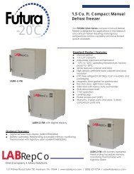
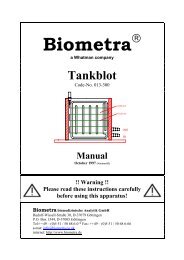
9.3 Changing Chart Paper<br />
To change the chart paper, complete the following steps:<br />
1. Locate the pressure sensitive buttons at the front, upper left<br />
of the recorder panel.<br />
2. Press and hold the change chart button for one second. The<br />
pen will move off the scale.<br />
3. Unscrew the center nut, remove the old chart paper, and<br />
install new chart paper. Carefully align the day and time with<br />
the reference mark on the recorder panel (a small groove on<br />
the left side of the panel, shown in Figure 4).<br />
4. Replace the center nut and hand tighten. Press the change<br />
chart button again to resume temperature recording.<br />
Imprinting<br />
Stylus<br />
Hub-Nut and<br />
Retaining Wire<br />
Figure 4. Six Inch Chart Recorder<br />
CHANGE CHART<br />
3<br />
Chart<br />
9.4 Calibration Adjustment<br />
This recorder has been accurately calibrated at the factory and<br />
retains calibration even during power interruptions. If required,<br />
however, adjustments can be made as follows:<br />
1. Run the unit continuously at the control setpoint temperature.<br />
Continue steady operation for at least two hours to provide<br />
adequate time for recorder response.<br />
2. Measure cabinet center solution temperature with a<br />
calibrated temperature monitor. (Solution temperature is<br />
measured inside the sensor bottle.)<br />
3. Compare the recorder temperature to the solution<br />
temperature. If necessary, adjust recorder by pressing the left<br />
(#1) and right (#2) chart buttons.<br />
Note: The stylus does not begin to move until the button is held<br />
for five seconds.<br />
1 2<br />
Figure 5. Chart Buttons<br />
8
Thermo Scientific <strong>Puffer</strong> <strong>Hubbard</strong> <strong>Lab</strong>oratory <strong>Refrigerators</strong><br />
Installation and Operation<br />
10 Maintenance<br />
10.1 Cleaning the Drawers and Cabinet Interior<br />
Pharmacy refrigerators come standard with drawers. All other<br />
refrigerators come standard with wire shelves. Additional<br />
drawers and/or shelves are offered as available options.<br />
To clean the drawers and cabinet interior, remove the drawers<br />
following the instructions below. Use a solution of water and a<br />
mild detergent. Rinse the drawers and wipe them dry with a soft<br />
cloth.<br />
10.2 Removing the Drawers<br />
The drawers in all models can be removed for cleaning.<br />
To remove the drawers, complete the following steps (refer to<br />
Figure 6):<br />
1. Pull the drawer toward you until the slide is fully extended.<br />
2. Lift the back of the drawer to disengage the mounting tab<br />
from the slot on the slide.<br />
3. Raise the back of the drawer almost to a vertical position and<br />
disengage the front mounting clips from the slide.<br />
The drawer slides are adjustable. You can position these slides in<br />
the vertical slots which are spaced at one-inch intervals.<br />
Tabs<br />
10.3 Reinstalling the Drawers<br />
To reinstall the drawers, complete the following steps:<br />
1. Pull both drawer slides toward you until the slides are fully<br />
extended.<br />
2. Position the drawer between the slides and insert the front<br />
mounting clips into the slots on front of the slides.<br />
3. Push the back of the drawer down between the slides and<br />
insert the drawer tabs into the back slots.<br />
Note: The drawers fit snugly between the slides. Push on the<br />
back of the drawer from the inside to insert the drawer<br />
tabs completely into the slots. Make sure both drawer<br />
tabs are aligned with the slots on the slides before<br />
pushing the drawer down between the slides.<br />
10.4 Cleaning the Condenser<br />
WARNING! Disconnect equipment from main<br />
power before attempting any maintenance to<br />
equipment or its controls.<br />
CAUTION! Condensers should be cleaned at least<br />
every six months. In heavy traffic areas, condensers<br />
load with dirt more quickly. Failure to keep the<br />
condenser clean can result in equipment warm-up or<br />
erratic temperatures.<br />
Periodically check the condenser to make sure that it is clean.<br />
In all models except for the 45 ft 3 sliding glass door model, the<br />
condenser is located in the top machine compartment.<br />
To clean the condenser:<br />
1. Disconnect the power.<br />
2. Remove the top grill (bottom front grill if you have a sliding<br />
glass door model).<br />
3. Use a vacuum cleaner with hose and brush attachments to<br />
clean the front face of the finned surface.<br />
4. Clean up any loose dust and replace the grill.<br />
5. Reconnect the power.<br />
Drawer slide<br />
Slot<br />
Figure 6. Drawer Removal<br />
9
Thermo Scientific <strong>Puffer</strong> <strong>Hubbard</strong> <strong>Lab</strong>oratory <strong>Refrigerators</strong><br />
Installation and Operation<br />
11 Troubleshooting<br />
WARNING! Troubleshooting procedures involve working with high voltages which can cause injury or death. Troubleshooting<br />
should only be performed by trained personnel.<br />
This section is a guide to troubleshooting equipment problems.<br />
Table 6.<br />
Troubleshooting Procedures<br />
Problem Cause Solution<br />
Unit does not operate<br />
or Power Failure<br />
Indicator is on.<br />
Temperature<br />
fluctuates.<br />
Unit warms up.<br />
Power supply<br />
1. Check that the cord is securely plugged-in.<br />
2. Plug another appliance into the outlet to see if it is live.<br />
3. If the outlet is dead, check the circuit breaker or fuses.<br />
Cold control Make sure that the cold control is set correctly. Refer to Section 7.1 on page 6.<br />
Condenser Make sure the condenser is clean. Refer to Section 10.4 on page 9.<br />
High pressure<br />
Door is open.<br />
Warm product recently<br />
loaded in unit.<br />
Power supply<br />
Compressor<br />
Check the system high-pressure cut-out button. This is an encapsulated control with a rubber boot<br />
over the reset button. To reset the control, push it down; use a blunt instrument to avoid tearing the<br />
boot.<br />
Make sure the door is completely closed.<br />
Allow ample time to recover from loading warm product.<br />
Check for proper voltage to the unit. If there is no voltage to the unit, call an electrician.<br />
1. If the compressor is not running, check if the unit has a power failure alarm. If the power failure<br />
alarm light is on, have an electrician check for proper voltage to the unit.<br />
2. If the compressor is running, open the door and look through the slotted air intake in the bottom<br />
of the evaporator cover to see if icing is present on the evaporator. If icing is present and there<br />
is no air flow behind evaporator, call technical service for assistance. The evaporator fans may<br />
be inoperative.<br />
3. If the compressor is running and there is airflow behind the evaporator, contact an authorized<br />
service provider or call the technical support hot line for assistance.<br />
10
Thermo Scientific <strong>Puffer</strong> <strong>Hubbard</strong> <strong>Lab</strong>oratory <strong>Refrigerators</strong><br />
Installation and Operation<br />
12 Accessories<br />
Alarm Systems<br />
Catalog<br />
Description<br />
No.<br />
Standard Remote Alarm. Provides audible and visual<br />
signal in the event of temperature rise or power failure.<br />
Adaptable to telephone switchboard. Can be located<br />
up to 1/3 mile (1760 ft/536 m) from cabinet. Must be<br />
used with electronic alarm system and connected to<br />
normally-open or normally-closed remote alarm<br />
contacts. Wire not included. Specify voltage when<br />
ordering. 5612<br />
Deluxe Electronic Remote Alarm System. User<br />
programmable to sound alarm in the event of<br />
temperature rise or power failure. Can dial up to four<br />
telephone numbers to advise of alarm condition across<br />
any telephone system which accepts pulse dialing.<br />
One System can monitor up to four individual cabinets.<br />
In addition, the System can monitor up to three groups<br />
of cabinets. Contact Customer Sales for detailed<br />
specifications. Customer installed. 6224<br />
Special Voltages<br />
Standard voltages are listed under Voltage in Specification Charts<br />
associated with each product category. Standard voltages are<br />
available at no charge; alternative voltages may be available at an<br />
extra charge. All voltages must be specified when ordering.<br />
Contact Customer Sales for more information.<br />
Low Voltage Protection<br />
Temperature Recorders<br />
All six inch recorders utilize pressure-sensitive chart paper<br />
(1 box @ 50 charts included); no inking is required..<br />
Chart Paper<br />
Description<br />
Catalog<br />
No.<br />
Voltage Safeguard. Free-standing. Helps protect electrical<br />
equipment from damage by boosting low voltage<br />
automatically. Provided with terminal board for direct<br />
wiring. Field installed. Specify voltage when ordering. 5575<br />
Description<br />
Catalog<br />
No.<br />
Temperature recorder, 6 in. circular chart, seven-day drive,<br />
panel mounted. Factory installed. Specify when<br />
ordering. 6183-7<br />
Temperature recorder, 6 in. circular chart, seven-day drive,<br />
free-standing, for all refrigerator models. Customer<br />
installed. Specify voltage when ordering. 6383-7<br />
Description<br />
Catalog<br />
No.<br />
Chart paper, package of 50, for six inch, seven-day<br />
recorder, -40°C to +25°C. 6184<br />
Casters<br />
Extra Shelves<br />
Description<br />
Catalog<br />
No.<br />
Dual-Wheel Casters. Set of four, two locking, two nonlocking,<br />
3 in. diameter, for 11.5, 23.3, 29.2, 51.1, and<br />
78.8 cu.ft models only. 6041-1<br />
Description<br />
Catalog<br />
No.<br />
Zinc Plated. Full Size. For use with 23.3, 45.8, 51.5, and<br />
78.8 cu.ft models only 6696<br />
Zinc Plated. Half size. For use with 23.3, 45.8, 51.5, and<br />
78.8 cu.ft models only. 6698<br />
Zinc Plated. Full size. For use with 29.2 cu.ft models only. 6695<br />
Zinc Plated. Half size. For use with 29.2 cu.ft models only. 6697<br />
Zinc Plated. Full size. For use with 11.5 cu.ft models only.<br />
Zinc Plated. For use with 4.9 cu.ft models only.<br />
6202<br />
7128<br />
Drawers<br />
Optional stainless steel drawers are offered as an alternative to<br />
standard shelving.<br />
Description<br />
Catalog<br />
No.<br />
For 4.9 cu.ft Undercounter Models<br />
For REL-404, roll-out drawer assembly, two drawers. 7129<br />
For 11.5 cu.ft Space Saver Models<br />
For REL-1204, roll-out drawer assembly, five drawers.<br />
6599<br />
For 23.3, 51.1, and 78.8 cu.ft Models<br />
For REL-2304, roll-out drawer assembly,<br />
six drawers, full adjustable, fully extendable. 6699<br />
For REL-5004, roll-out drawer assembly,<br />
12 drawers, fully adjustable, fully extendable. 6700<br />
For REL-7504, roll-out drawer assembly, 18 drawers, fully<br />
adjustable, fully extendable. 6701<br />
Additional stainless steel drawers, for 23.3, 51.1, and<br />
78.8 cu.ft models. 6702<br />
For 45.8 cu.ft Models only<br />
For REL-4504, roll-out drawer assembly, six additional<br />
stainless steel drawers, fully adjustable, fully<br />
extendable. 6703<br />
For 29.2 cu.ft Models only<br />
For REL-3004, roll-out drawer assembly, six additional<br />
stainless steel drawers, fully adjustable, fully<br />
extendable. 6704<br />
11
Thermo Scientific <strong>Puffer</strong> <strong>Hubbard</strong> <strong>Lab</strong>oratory <strong>Refrigerators</strong><br />
Installation and Operation<br />
Extended Warranty Options<br />
Note: In addition the standard full warranty on the complete<br />
product (USA and Canada), an additional four year protection on<br />
compressor and compressor parts can be supplied . This<br />
additional coverage must be purchased at the time of original<br />
product purchase. Under this contract, the manufacturer agrees to<br />
furnish a compressor FOB our factory to replace one which has<br />
been determined to be defective by manufacturer or a factory<br />
authorized Service Agency.<br />
Catalog<br />
Description<br />
No.<br />
Extended Four-Year Compressor Parts Contract, all<br />
refrigerators. 6069<br />
Extended 12-Month Comprehensive Coverage, for all<br />
models, provides additional 12-month warranty<br />
coverage, parts and labor. Contact Customer Sales for<br />
details. 6613<br />
12
Thermo Scientific <strong>Puffer</strong> <strong>Hubbard</strong> <strong>Lab</strong>oratory <strong>Refrigerators</strong><br />
Installation and Operation<br />
WEEE Compliance<br />
WEEE Compliance. This product is required to comply with the European<br />
Union’s Waste Electrical & Electronic Equipment (WEEE) Directive 2002/96EC.<br />
It is marked with the following symbol. Thermo Fisher Scientific has contracted<br />
with one or more recycling/disposal companies in each EU Member State, and<br />
this product should be disposed of or recycled through them. Further information<br />
on our compliance with these Directives, the recyclers in your country, and<br />
information on Thermo Scientific products which may assist the detection of<br />
substances subject to the RoHS Directive are available at www.thermo.com/<br />
WEEE Konformittät. Dieses Produkt muss die EU Waste Electrical &<br />
Electronic Equipment (WEEE) Richtlinie 2002/96EC erfüllen. Das Produkt ist<br />
durch folgendes Symbol gekennzeichnet. Thermo Fisher Scientific hat<br />
Vereinbarungen getroffen mit Verwertungs-/Entsorgungsanlagen in allen EU-<br />
Mitgliederstaaten und dieses Produkt muss durch diese Firmen widerverwetet<br />
oder entsorgt werden. Mehr Informationen über die Einhaltung dieser<br />
Anweisungen durch Thermo Scientific, dieVerwerter und Hinweise die Ihnen<br />
nützlich sein können, die Thermo Fisher Scientific Produkte zu identizfizieren,<br />
die unter diese RoHS. Anweisungfallen, finden Sie unter www.thermo.com/<br />
Conformità WEEE. Questo prodotto deve rispondere alla direttiva dell’ Unione<br />
Europea 2002/96EC in merito ai Rifiuti degli Apparecchi Elettrici ed Elettronici<br />
(WEEE). È marcato col seguente simbolo.Thermo Fischer Scientific ha stipulato<br />
contratti con una o diverse società di riciclaggio/smaltimento in ognuno degli<br />
Stati Membri Europei. Questo prodotto verrà smaltito o riciclato tramite queste<br />
medesime. Ulteriori informazioni sulla conformità di Thermo Fisher Scientific<br />
con queste Direttive, l’elenco delle ditte di riciclaggio nel Vostro paese e<br />
informazioni sui prodotti Thermo Scientific che possono essere utili alla<br />
rilevazione di sostanze soggette alla Direttiva RoHS sono disponibili sul sito<br />
www.thermo.com/<br />
Conformité WEEE. Ce produit doit être conforme à la directive euro-péenne<br />
(2002/96EC) des Déchets d’Equipements Electriques et Electroniques (DEEE). Il<br />
est marqué par le symbole suivant. Thermo Fisher Scientific s’est associé avec<br />
une ou plusieurs compagnies de recyclage dans chaque état membre de l’union<br />
européenne et ce produit devraitêtre collecté ou recyclé par celles-ci. Davantage<br />
d’informations sur laconformité de Thermo Fisher Scientific à ces directives, les<br />
recycleurs dans votre pays et les informations sur les produits Thermo Fisher<br />
Scientific qui peuvent aider le détection des substances sujettes à la directive<br />
RoHS sont disponibles sur www.thermo.com/<br />
Great Britain<br />
Deutschland<br />
Italia<br />
France<br />
13
Important<br />
For your future reference and when contacting the factory, please have the<br />
following information readily available:<br />
Model Number:<br />
Serial Number:<br />
Date Purchased:<br />
The above information can be found on the dataplate attached to the<br />
equipment. If available, please provide the date purchased, the source of<br />
purchase (manufacturer or specific agent/rep organization), and purchase<br />
order number.<br />
IF YOU NEED ASSISTANCE:<br />
SALES DIVISION<br />
Phone:<br />
1-866-984-3766 (866-9-THERMO)<br />
LABORATORY PARTS and SERVICE<br />
Phone: 1-800-438-4851<br />
TECHNICAL SUPPORT<br />
Phone: 1-800-438-4851
Thermo Fisher Scientific Inc.<br />
275 Aiken Road<br />
Asheville, NC 28804<br />
United States<br />
www.thermofisher.com<br />
34830H62 Rev. A