Puffer Hubbard Lab Refrigerators Manual-FC-LR-RX - LABRepCo
Puffer Hubbard Lab Refrigerators Manual-FC-LR-RX - LABRepCo
Puffer Hubbard Lab Refrigerators Manual-FC-LR-RX - LABRepCo

Create successful ePaper yourself
Turn your PDF publications into a flip-book with our unique Google optimized e-Paper software.
Thermo Scientific <strong>Puffer</strong> <strong>Hubbard</strong> <strong>Lab</strong>oratory <strong>Refrigerators</strong><br />
Installation and Operation<br />
9 Chart Recorders<br />
Panel-mounted six inch recorders are available as options on all<br />
models. Recorder operation begins when the system is powered<br />
on.<br />
9.1 Set Up and Operation<br />
To prepare the recorder to function properly, complete the<br />
following steps:<br />
1. Open the recorder door to access the recorder.<br />
2. Connect the nine volt DC battery located at the recorder’s<br />
upper right corner. This battery provides back-up power.<br />
3. Install clean chart paper (refer to Section 9.3 below).<br />
4. Remove the plastic cap from the pen stylus and close the<br />
recorder door.<br />
Note: The recorder may not respond until the system reaches<br />
temperatures within the recorder’s range.<br />
Chart Buttons<br />
9 Volt Battery<br />
9.2 Power Supply<br />
The recorder normally uses AC power when the system is<br />
operating. If AC power fails, the LED indicator flashes to alert<br />
you to a power failure. The recorder continues sensing cabinet<br />
temperature and the chart continues turning for approximately<br />
24 hours with back-up power provided by the nine-volt battery.<br />
The LED indicator glows continuously when main power is<br />
functioning and the battery is charged.<br />
When the battery is low, the LED flashes to indicate that the<br />
battery needs to be changed.<br />
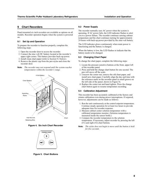
9.3 Changing Chart Paper<br />
To change the chart paper, complete the following steps:<br />
1. Locate the pressure sensitive buttons at the front, upper left<br />
of the recorder panel.<br />
2. Press and hold the change chart button for one second. The<br />
pen will move off the scale.<br />
3. Unscrew the center nut, remove the old chart paper, and<br />
install new chart paper. Carefully align the day and time with<br />
the reference mark on the recorder panel (a small groove on<br />
the left side of the panel, shown in Figure 4).<br />
4. Replace the center nut and hand tighten. Press the change<br />
chart button again to resume temperature recording.<br />
Imprinting<br />
Stylus<br />
Hub-Nut and<br />
Retaining Wire<br />
Figure 4. Six Inch Chart Recorder<br />
CHANGE CHART<br />
3<br />
Chart<br />
9.4 Calibration Adjustment<br />
This recorder has been accurately calibrated at the factory and<br />
retains calibration even during power interruptions. If required,<br />
however, adjustments can be made as follows:<br />
1. Run the unit continuously at the control setpoint temperature.<br />
Continue steady operation for at least two hours to provide<br />
adequate time for recorder response.<br />
2. Measure cabinet center solution temperature with a<br />
calibrated temperature monitor. (Solution temperature is<br />
measured inside the sensor bottle.)<br />
3. Compare the recorder temperature to the solution<br />
temperature. If necessary, adjust recorder by pressing the left<br />
(#1) and right (#2) chart buttons.<br />
Note: The stylus does not begin to move until the button is held<br />
for five seconds.<br />
1 2<br />
Figure 5. Chart Buttons<br />
8