Manual C-159 Rev 11-07 - Despatch Industries
Manual C-159 Rev 11-07 - Despatch Industries
Manual C-159 Rev 11-07 - Despatch Industries

You also want an ePaper? Increase the reach of your titles
YUMPU automatically turns print PDFs into web optimized ePapers that Google loves.
P/N 125166<br />
REV. <strong>11</strong>/<strong>07</strong><br />
C-<strong>159</strong><br />
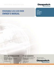
LCC SERIES OVENS<br />
INSTRUCTION MANUAL<br />
Model Volts Phase Hz Heater Watts Total<br />
LCC 1-<strong>11</strong> 240 1 50/60 3,000 14.2<br />
LCC 1-<strong>11</strong>N 240 1 50/60 3,000 14.2<br />
LCC 1-54 240 1 50/60 6,000 26.7<br />
LCC 1-54N 240 1 50/60 6,000 26.7<br />
LCC 1-54NV 240 1 50/60 6,000 26.7<br />
LCC 1-87 240 1 50/60 9,000 42.2<br />
LCC 1-87N 240 1 50/60 9,000 42.2<br />
LCC 1-87NV 240 1 50/60 9,000 42.2<br />
Prepared by:<br />
<strong>Despatch</strong> <strong>Industries</strong><br />
P.O. Box 1320<br />
Minneapolis, MN 55420-1320<br />
Customer Service 800-473-7373
Notice<br />
Users of this equipment must comply with operating procedures and training of<br />
operation personnel as required by the Occupational Safety and Health Act (OSHA) of<br />
1970, Section 6 and relevant safety standards, as well as other safety rules and<br />
regulations of state and local governments. Refer to the relevant safety standards in<br />
OSHA and National Fire Protection Association (NFPA), section 86 of 1990.<br />
Caution<br />
Setup and maintenance of the equipment should be performed by qualified personnel<br />
who are experienced in handling all facets of this type of system. Improper setup and<br />
operation of this equipment could cause an explosion that may result in equipment<br />
damage, personal injury or possible death.<br />
Thank you for choosing <strong>Despatch</strong> <strong>Industries</strong>. We appreciate<br />
the opportunity to work with you and to meet your heat<br />
processing needs. We believe that you have selected the<br />
finest equipment available in the heat processing industry.<br />
At <strong>Despatch</strong>, our service does not end after the purchase<br />
and delivery of our equipment. For this reason we have<br />
created the Service Products Division within <strong>Despatch</strong>. The<br />
Service Products Division features our Response Center for<br />
customer service. The Response Center will direct and<br />
track your service call to ensure satisfaction.<br />
Whenever you need service or replacement parts, contact<br />
the Response Center at 1-800-473-7373: FAX 612-781-<br />
5353.<br />
Thank you for choosing <strong>Despatch</strong>.<br />
Sincerely,<br />
<strong>Despatch</strong> <strong>Industries</strong>
PREFACE<br />
This manual is your guide to the <strong>Despatch</strong> oven. It is organized to give you the<br />
information you need quickly and easily.<br />
The INTRODUCTION section provides an overview<br />
of the <strong>Despatch</strong> oven.<br />
The THEORY OF OPERATION section details the<br />
function and operation of assemblies and subassemblies<br />
on the <strong>Despatch</strong> oven.<br />
Read NOTE: the entire<br />
INTRODUCTION and THEORY<br />
OF OPERATION before<br />
installing the oven.<br />
The INSTRUCTIONS section provides directions on unpacking, installing, operating<br />
and maintaining the <strong>Despatch</strong> oven.<br />
The APPENDIX section contains Special Instructions<br />
for operating the control instrument, a Troubleshooting<br />
Table, and a list of Accessories.<br />
An efficient way to learn about the oven would be to<br />
read the manual while working with the corresponding<br />
oven control system. This will give you practical<br />
hands-on experience with information in the manual<br />
and the oven.<br />
WARNING:<br />
Failure to heed warnings in this<br />
instruction manual and on the<br />
oven could result in personal<br />
injury, property damage or<br />
death.<br />
Before operating the equipment, be sure you understand all of the technical information<br />
contained in this manual. Information skipped, not understood or misunderstood could<br />
create the possibility of operating the equipment in an unsafe manner. This can cause<br />
damage to the oven or personnel or reduce the efficiency of the equipment.<br />
i
TABLE OF CONTENTS<br />
INTRODUCTION ............................................................................................................. 1<br />
Special Features .................................................................................................. 1<br />
SPECIFICATIONS .......................................................................................................... 2<br />
Dimensions ........................................................................................................... 2<br />
Capacities ............................................................................................................. 3<br />
Power ................................................................................................................... 3<br />
Temperature ......................................................................................................... 4<br />
THEORY OF OPERATION ............................................................................................. 5<br />
Construction ......................................................................................................... 6<br />
Cooling ................................................................................................................. 6<br />
Inert Atmosphere .................................................................................................. 6<br />
HEPA Filters ......................................................................................................... 7<br />
Definitions .................................................................................................. 7<br />
Packaging and Shipping ............................................................................ 7<br />
Handling ..................................................................................................... 8<br />
HEPA Filter Validation Testing .................................................................. 8<br />
D.O.P. Testing ................................................................................ 8<br />
Class 100 Testing ........................................................................... 8<br />
Validation Testing ........................................................................... 9<br />
The Necessity of the Burn-off Process ...................................................... 9<br />
Filter Unit Replacement ............................................................................ 9<br />
CONTROL Instrument ........................................................................................ 10<br />
HIGH LIMIT Instrument ...................................................................................... 10<br />
Product High Limit Instrument ................................................................. 10<br />
Oven High Limit Instrument ..................................................................... <strong>11</strong><br />
INSTRUCTIONS ........................................................................................................... 12<br />
Unpacking and Inspection .................................................................................. 12<br />
Set-up ................................................................................................................. 13<br />
HEPA Filter Installation ............................................................................ 15<br />
HEPA Filter Burn-off ................................................................................ 16<br />
OPERATING ................................................................................................................. 18<br />
Loading the Oven ............................................................................................... 18<br />
Pre-Startup Checklist .......................................................................................... 19<br />
Startup ................................................................................................................ 19<br />
Shut Down ............................................................................................... 22<br />
Maintenance ....................................................................................................... 23<br />
Checklist .................................................................................................. 23<br />
Tests ................................................................................................................... 24<br />
Nitrogen Supply Check ........................................................................... 24<br />
iii
Control Output Check .............................................................................. 24<br />
Thermocouple Test .................................................................................. 25<br />
Safety Controls ........................................................................................ 25<br />
Replacement ...................................................................................................... 26<br />
Parts ........................................................................................................ 26<br />
CONTROL Instrument ............................................................................. 26<br />
Fan Motor ................................................................................................ 27<br />
Replacing HIGH LIMIT ............................................................................ 28<br />
Thermocouple Break Protection .............................................................. 29<br />
Replacing the Thermocouple ........................................................ 29<br />
Heater Unit ............................................................................................... 30<br />
APPENDIX .................................................................................................................... 31<br />
Troubleshooting .................................................................................................. 31<br />
Factory Installed Options .................................................................................... 33<br />
Drawings ............................................................................................................. 34<br />
iv
INTRODUCTION<br />
This section provides an overview of the <strong>Despatch</strong> LCC Series oven. The LCC offers<br />
HEPA filtration for processes where minimization of contamination is essential. Fresh<br />
air and nitrogen (noted with an N suffix) models are available.<br />
Special Features<br />
The removable HEPA (High Efficiency Particulate Air) filter is designed to provide a<br />
constant flow of 99.97% clean air to the product. Other special features include:<br />
Digital TEMP CONTROL and manual reset HIGH LIMIT to protect the chamber<br />
workload as well as the oven itself.<br />
Stainless steel interior with all interior seams continuously welded on the<br />
insulation side to protect the work chamber from contamination and to permit<br />
chamber washing without damaging insulation.<br />
Silicon door seals, shaft seals and gasketing (Viton Fluorocarbon on NV<br />
models).<br />
Door seals and interior chamber walls are removable for cleaning.<br />
Heater with a five year warranty.<br />
Cooling coil to provide rapid cooldown and low temperature operation (nitrogen<br />
models only).<br />
Scratch-resistant SilverClay® baked enamel exteriors and a stainless steel<br />
interior for easy cleaning.<br />
Silicon-free construction on NV models.<br />
Nitrogen operation (N and NV models only)<br />
1
SPECIFICATIONS<br />
Dimensions<br />
Model Chamber Size, inches (cm) Capacity,<br />
ft 3 (liters)<br />
Overall Size, inches (cm)<br />
W D H W D H<br />
Maximum<br />
Number of<br />
Shelves<br />
LCC 1-<strong>11</strong> 10<br />
(25)<br />
14<br />
(35)<br />
14<br />
(35)<br />
1.1<br />
(31)<br />
25<br />
(64)<br />
21<br />
(53)<br />
32<br />
(81)<br />
5<br />
LCC 1-<strong>11</strong>N 10<br />
(25)<br />
14<br />
(35)<br />
14<br />
(35)<br />
1.1<br />
(31)<br />
26<br />
(66)<br />
21<br />
(53)<br />
32<br />
(81)<br />
5<br />
LCC 1-54 18<br />
(46)<br />
20<br />
(51)<br />
26<br />
(66)<br />
5.4<br />
(153)<br />
34<br />
(153)<br />
29<br />
(74)<br />
43<br />
(109)<br />
<strong>11</strong><br />
LCC 1-54N,<br />
LCC 1-54NV<br />
18<br />
(46)<br />
20<br />
(51)<br />
26<br />
(66)<br />
5.4<br />
(153)<br />
34<br />
(153)<br />
29<br />
(74)<br />
43<br />
(109)<br />
<strong>11</strong><br />
LCC 1-87 22<br />
(56)<br />
20<br />
(51)<br />
34<br />
(86)<br />
8.7<br />
(248)<br />
39<br />
(99)<br />
29<br />
(74)<br />
52<br />
(132)<br />
14<br />
LCC 1-87N,<br />
LCC 1-87NV<br />
22<br />
(56)<br />
20<br />
(51)<br />
34<br />
(86)<br />
8.7<br />
(248)<br />
39<br />
(99)<br />
29<br />
(74)<br />
52<br />
(132)<br />
14<br />
2
Capacities<br />
Model LCC 1-<strong>11</strong> LCC 1-<strong>11</strong>N LCC 1-54 LCC 1-54N,<br />
LCC 1-54NV<br />
LCC 1-87<br />
LCC 1-87N,<br />
LCC 1-87NV<br />
Maximum<br />
Load<br />
Maximum<br />
Shelf Load<br />
Lbs 25 25 150 150 200 200<br />
Lbs 10 10 25 25 25 25<br />
Recirculating<br />
Fan<br />
CFM<br />
H.P.<br />
265<br />
1/4<br />
265<br />
1/4<br />
400<br />
1/4<br />
400<br />
1/4<br />
990<br />
3/4<br />
990<br />
3/4<br />
Approximate<br />
Net Weight<br />
Lbs.<br />
KG<br />
285<br />
129<br />
285<br />
129<br />
380<br />
172<br />
380<br />
172<br />
500<br />
227<br />
500<br />
227<br />
Shipping<br />
Weight<br />
(approximate)<br />
Lbs.<br />
KG<br />
400<br />
181<br />
400<br />
181<br />
615<br />
279<br />
615<br />
279<br />
750<br />
341<br />
750<br />
341<br />
Power<br />
Line voltages may vary in some geographical locations. If your line voltage is much<br />
lower than the oven voltage rating, warm up time will be longer and motors may<br />
overload or run hot. If your line voltage is higher than name plate rating, the motor may<br />
run hot and draw excessive amps. If the line voltage varies more than 10% from the<br />
oven voltage rating, some electrical components such as relays, temperature controls,<br />
etc. may operate erratically.<br />
Model Volts * Amps Hertz Heater Phase KW Cord and Plug<br />
LCC 1-<strong>11</strong> 240 14.2 50/60 1 3 None, Hardwired<br />
LCC 1-<strong>11</strong>N 240 14.2 50/60 1 3 None, Hardwired<br />
LCC 1-54 240 26.7 50/60 1 6 None, Hardwired<br />
LCC 1-54N 240 26.7 50/60 1 6 None, Hardwired<br />
LCC 1-54NV 240 26.7 50/60 1 6 None, Hardwired<br />
LCC 1-87 240 42.2 50/60 1 9 None, Hardwired<br />
LCC 1-87N 240 42.2 50/60 1 9 None, Hardwired<br />
LCC 1-87NV 240 42.2 50/60 1 9 None, Hardwired<br />
* Oven designed for 240 volts (see nameplate on oven) will operate satisfactorily on a minimum of 208 volts, but with a 25%<br />
reduction in heater power. If your power characteristics are lower, contact <strong>Despatch</strong> <strong>Industries</strong>.<br />
3
Temperature<br />
Model LCC 1-<strong>11</strong> LCC 1-<strong>11</strong>N LCC 1-54 LCC 1-54N,<br />
LCC 1-54V<br />
LCC 1-87<br />
LCC 1-87N,<br />
LCC 1-87NV<br />
Time to<br />
Temperature<br />
(approximate<br />
minutes)<br />
25 C -<br />
100 C<br />
25 C -<br />
200 C<br />
25 C -<br />
260 C<br />
4 4 5 5 4 4<br />
13 13 14 14 12 12<br />
20 20 23 23 18 18<br />
Recovery Time<br />
Door Open 1<br />
Minute<br />
(approximate<br />
minutes)<br />
Temperature<br />
Uniformity at<br />
(maximum)<br />
125 C 0.5 0.5 1 1 1 1<br />
200 C 1 1 2 2 2 2<br />
260 C 2.5 2.5 3 3 3 3<br />
125 C ± 1 C ± 1 C ± 2 C ± 2 C ± 1 C ± 1 C<br />
200 C ± 2 C ± 2 C ± 2 C ± 2 C ± 2 C ± 2 C<br />
260 C ± 3 C ± 3 C ± 3 C ± 3 C ± 3 C ± 3 C<br />
Maximum Operating<br />
Temperature<br />
260 C 260 C 260 C 260 C 260 C 260 C<br />
Minimum<br />
Operating<br />
Temperature<br />
Above Ambient<br />
(approximate)<br />
Cooling Time<br />
Empty Oven<br />
(approximate<br />
minutes)<br />
Without<br />
Water<br />
Cooling<br />
With<br />
Water<br />
Cooling<br />
200 C -<br />
50 C<br />
48 C 53 C 34 C 85 C 54 C <strong>11</strong>6 C<br />
9 C 9 C 18 C 18 C 35 C 40 C<br />
63 64 48 58 54 78<br />
Control Stability ± 0.3 C ± 0.3 C ± 0.3 C ± 0.3 C ± 0.3 C ± 0.3 C<br />
Repeatability ± 0.5 C ± 0.5 C ± 0.5 C ± 0.5 C ± 0.5 C ± 0.5 C<br />
4
THEORY OF OPERATION<br />
The THEORY OF OPERATION section details the function and operation of the<br />
<strong>Despatch</strong> LCC Series Ovens.<br />
The LCC series oven is a class 100 clean room oven with HEPA (High Efficiency<br />
Particulate Air) filtration. This oven is ideal for processes where minimization of<br />
contamination is essential.<br />
Forced convected airflow, provides rapid uniform distribution of heat. An absolute<br />
HEPA (High Efficiency Particulate Air) filter is mounted in a stainless steel frame in the<br />
supply plenum. These filters are 99.97% effective in filtering 0.3 micron particles.<br />
5
Construction<br />
The LCC series oven has a type 304-2B stainless steel interior. All interior seams are<br />
continuously welded on the insulation side. This protects the work chamber from<br />
contaminated air and permits chamber washing without damaging the insulation.<br />
Interior chamber walls and silicon door gaskets (Viton Fluorocarbon on NV models) can<br />
be easily removed for cleaning. Heater frame, fan wheel and motor shaft are<br />
constructed of stainless steel.<br />
Exteriors are steel finished in SilverClay enamel, baked to a 2H hardness for chip and<br />
scratch resistance. All controls are mounted on the front of the oven for easy operation<br />
and readability. Two electropolished stainless steel wire shelves are provided. The<br />
shelves are removable and adjustable on two inch centers.<br />
Cooling<br />
Air models have an adjustable fresh air damper which allows cooling of the oven.<br />
Nitrogen models have a stainless steel water coil. When used in conjunction with the<br />
optional flowmeter the cooling coil permits rapid cooldown and low temperature<br />
operation.<br />
Inert Atmosphere<br />
An inert atmosphere option offers the advantages of both a clean room oven and inert<br />
atmosphere oven. The nitrogen portion for the LCC series oven includes a manual<br />
three way valve and two flowmeters, connected by piping to the inlet connection on the<br />
lower back panel marked nitrogen supply.<br />
6
HEPA Filters<br />
Absolute HEPA (High Efficiency Particulate Air) filters are used to limit particulate size<br />
in the work chamber to 0.3 microns or less. The gentle entrance and exit air velocity to<br />
and from the HEPA filter results in high efficiency and long life for the HEPA filters.<br />
Chamber NOTE: temperature transitions must not<br />
Definitions<br />
exceed 1.5 C/minute in order to maintain<br />
class 100 chamber conditions. Optional<br />
HEPA - High Efficiency Particulate Air<br />
filter is available for transition rates up to 5<br />
C/minute. Consult the factory.<br />
Burn-Off - A process for getting rid of the<br />
binder and D.O.P. contained in the filter<br />
from the manufacturing and testing function.<br />
D.O.P. - Dioctyl Phthalate - Aerosol particles of submicron size used in the testing<br />
phase to spot defects or measure filter efficiency.<br />
Binder - An organic substance that is used in the construction of the filter that gives<br />
some structural strength to the media.<br />
Packaging and Shipping<br />
Packaging practice varies among the filter unit manufacturers. Normally units are<br />
packaged in cardboard cartons with various approaches for internal strengthening and<br />
impact-resistance of the container. The shipping carton normally is marked with a<br />
vertical arrow and "This Side Up". A filter unit is placed in the carton so that the pleated<br />
folds are vertical (running from top to bottom - not side to side).<br />
Filters should be shipped, handled and stored with the pleats in the vertical position. If<br />
shipped with the pleats in the horizontal position, the filter medium may break at the<br />
adhesive line. If handled or stored with the pleats in the horizontal position the pleats<br />
may sag.<br />
Moreover, the filter unit should be installed with the pleats in the vertical position. When<br />
installed in the horizontal position the pleats form shelves for the collection of entrapped<br />
material. The accumulated weight of this material causes sagging and leads to an early<br />
failure of the unit.<br />
7
Handling<br />
The filter is shipped in the original carton or package that the filter manufacturer uses.<br />
This will give good storage and maximum protection from dirt and moisture.<br />
HEPA filters should be stored and moved in the shipping carton with in the upright<br />
position. Handling should be kept to a minimum. During installation the filter should be<br />
removed from the shipping carton and installed directly into the oven.<br />
If for any reason an unpackaged filter unit must be placed with its face on the floor or<br />
other surface, the surface must be cleared of every object or irregularity which might<br />
damage the filter pack.<br />
HEPA Filter Validation Testing<br />
This section describes the <strong>Despatch</strong> position and recommendations for HEPA filter<br />
testing and oven validation procedures. <strong>Despatch</strong> guarantees that the filters will meet<br />
specified efficiency ratings when the filter is:<br />
properly installed<br />
run at or below 200 C, at a constant temperature<br />
run before burn-in<br />
D.O.P. Testing<br />
In D.O.P. testing aerosol particles of submicron size are used to spot defects or<br />
measure filter efficiency. Degenerative by-products of this test are distributed<br />
throughout the oven chamber upon heat-up. Therefore <strong>Despatch</strong> does not recommend<br />
D.O.P. filter testing.<br />
Class 100 Testing<br />
<strong>Despatch</strong> guarantees the environment within the oven to be Class 100. This<br />
classification is based upon measurement of the particulate level within the oven work<br />
chamber.<br />
Class 100 testing may be performed before or after a proper filter burn-in procedure<br />
has been performed. <strong>Despatch</strong> will guarantee Class 100 conditions measurements<br />
based on two methods of test. The direct method of test employs an extraction type<br />
particulate analyzer. The indirect method involves particle settling over a specified<br />
8
period of time onto a clean disk.<br />
Validation Testing<br />
Based on the issues discussed in this section, <strong>Despatch</strong> recommends the following test<br />
sequence for pharmaceutical Class 100 ovens.<br />
1. Proper installation of the HEPA filters.<br />
2. Cold D.O.P. challenge to determine integrity of oven chamber and filter gaskets.<br />
3. Proper filter burn-off procedure.<br />
4. Class 100 testing inside the work chamber.<br />
The Necessity of the Burn-off Process<br />
HEPA filters contain a binder material which protects the filter media during production<br />
and shipping. This smoke is typically not desirable during normal operation of the oven.<br />
Burning off the binder will ensure a clean process at elevated temperatures.<br />
When the binder is burned out of the filter media, the filter becomes very fragile, too<br />
fragile to withstand normal shipping and handling. For this reason, <strong>Despatch</strong> does not<br />
perform the burn-off procedure.<br />
Filter Unit Replacement<br />
Replacement of the filter unit will be necessary for various reasons.<br />
Resistance, or pressure drop, across the filter unit. Maximum level of resistance<br />
in inches (water gauge) will vary depending upon the operation of the filter and<br />
the available fan capacity. Adequate fan capacity must be available.<br />
Loss of efficiency (leakage), determined from air-sampling measurements made<br />
downstream of the filter unit.<br />
Visible damage or rupture of the filter media in a unit.<br />
Change in process application.<br />
Excessive build-up of lint or combustible particulate matter on the filter unit.<br />
9
Water droplets in airstream through filter, free water (RH = 100%), will saturate<br />
filter very quickly and may cause burnout or holes in burned off filter media.<br />
High level of radiation in the vicinity of the filter unit.<br />
CONTROL Instrument<br />
The CONTROL instrument operates the heating element in response to the entered<br />
temperature setpoint. It provides digital indication of the setpoint and actual oven<br />
temperature. Please refer to the operator’s manual for the CONTROL instrument<br />
provided with the oven, for detailed operating instructions.<br />
HIGH LIMIT Instrument<br />
The purpose of the HIGH LIMIT instrument is to protect the product and/or the oven<br />
from excessively high temperatures. If the setting on the HIGH LIMIT is exceeded, the<br />
heating process will discontinue.<br />
The HIGH LIMIT instrument must be set to a temperature slightly higher than the<br />
CONTROL instrument setpoint or to a temperature that should not be exceeded in the<br />
process. The instrument must be manually reset by pushing the red button.<br />
Product High Limit<br />
Instrument<br />
If the product being processed has a<br />
critical high temperature limit, the HIGH<br />
LIMIT instrument should be used as a<br />
product high limit instrument. The HIGH<br />
LIMIT instrument should be set to a<br />
temperature somewhat below the<br />
temperature at which the product could be<br />
damaged. Use the CONTROL instrument<br />
or a pyrometer to determine the product<br />
setting. If the destructive temperature of<br />
the product is already known, this could be<br />
used as a point below which the product<br />
HIGH LIMIT is set.<br />
NOTE:<br />
<strong>Despatch</strong> <strong>Industries</strong> cannot be responsible<br />
for either the process, the process<br />
temperature used, or for the quality of the<br />
product being processed. It is the<br />
responsibility of the purchaser and operator<br />
to see that the product undergoing<br />
processing in a <strong>Despatch</strong> oven is<br />
adequately protected from damage.<br />
Carefully following the instructions in this<br />
manual will assist the purchaser and<br />
operator in fulfilling that responsibility.<br />
10
Oven High Limit Instrument<br />
If the product does not have a critical high temperature limit, the HIGH LIMIT can be<br />
used as an oven HIGH LIMIT instrument. An oven HIGH LIMIT instrument protects<br />
oven equipment.<br />
Since the HIGH LIMIT instrument does not show the temperature, it can be properly set<br />
only after oven is in operation. Until then, the HIGH LIMIT should be set at maximum<br />
position so all preliminary testing and adjusting can be done.<br />
Never operate the oven at a temperature in excess of the maximum operating<br />
temperature of 260 C (500 F).<br />
<strong>11</strong>
INSTRUCTIONS<br />
The INSTRUCTIONS section provides directions on unpacking, installation, operation<br />
and maintenance of the <strong>Despatch</strong> LCC Series Ovens.<br />
Unpacking and Inspection<br />
Remove all packing materials and thoroughly inspect the oven for damage of any kind<br />
that could have occurred during shipment.<br />
See whether the carton and plastic cover sheet inside carton are still in good<br />
condition.<br />
Look at all outside surfaces and corners of the oven for scratches and dents.<br />
Check the oven controls and indicators for normal movement, bent shafts,<br />
cracks, chips or missing parts such as knobs and lenses.<br />
Check the door and latch for smooth operation.<br />
Check the filter carton for damage.<br />
If there is damage that could have happened during shipment follow these instructions:<br />
1. Contact the shipper immediately and file a written damage claim.<br />
2. Contact <strong>Despatch</strong> <strong>Industries</strong> to report your findings and to order replacement<br />
parts for those that were damaged or missing.<br />
3. Please send a copy of your filed damage claims to <strong>Despatch</strong>.<br />
4. Check to make sure you have received all the required materials. Your shipment<br />
should include:<br />
One (1) <strong>Despatch</strong> oven,<br />
One (1) Filter,<br />
One (1) oven instruction manual,<br />
One (1) control instrument instruction manual,<br />
One (1) high limit instrument manual,<br />
One (1) Warranty card,<br />
Two (2) Shelves<br />
One (1) Package containing four rubber pads<br />
If any of these items are missing from the packaged contents, contact <strong>Despatch</strong><br />
12
<strong>Industries</strong> to have the appropriate materials forwarded to you. Any optional<br />
accessories ordered will be shipped separately.<br />
5. Complete the warranty card and mail it to <strong>Despatch</strong> within 15 days after receipt<br />
of the equipment.<br />
Set-up<br />
1. Remove adhesive backing sheet from the rubber pads.<br />
2. Attach rubber pads to the bottom corners of the oven.<br />
3. Place oven on a bench top or an optional<br />
cabinet base. The oven must have a minimum<br />
of two (2) inches clearance in the rear to<br />
provide proper ventilation. The oven may be<br />
placed next to another cabinet, or next to<br />
another oven, with three-quarters (¾) of an inch clearance (the doors are still<br />
open).<br />
4. Make sure oven is level and plumb; this will assure proper heat distribution and<br />
operation of all mechanical components.<br />
5. (Nitrogen models only) Connect the DO WARNING: NOT use with other than inert gases<br />
nitrogen supply line (from your (nitrogen model only).<br />
plant nitrogen system) to the inlet<br />
marked nitrogen supply on the oven<br />
rear panel. The nitrogen supply to the oven must not exceed 40 PSI.<br />
6. (Nitrogen models only) Install water<br />
connection for cooling coils.<br />
a. Pipe the coil with a<br />
three-way water supply/drain<br />
valve on the inlet (bottom<br />
fitting) and a vacuum breaker<br />
valve at the high point of the<br />
drain line. This will keep<br />
water moving through the<br />
cooling coil, minimizing<br />
steam generation. The water<br />
supply to the oven must not exceed 100 PSI.<br />
b. Mount the optional cooling water flowmeter (included in cooling kit part<br />
number 090020.)<br />
13<br />
DO WARNING: NOT use oven in wet,<br />
corrosive, or explosive<br />
atmosphere.<br />
CAUTION:<br />
The design and piping of the drain system<br />
should preclude the possibility of operator<br />
injury from high temperature or pressure<br />
buildup. Piping must be able to withstand<br />
short periods of up to 450 temperatures.<br />
Drain lines should be insulated or warning<br />
labels installed for the distance that a<br />
hazard exists.
The brass needle valve on the face of the<br />
water flowmeter can be used for adjusting the<br />
water flow or shutting off the water flow.<br />
WARNING: never allow<br />
drain to be plugged as a<br />
hot oven will generate a<br />
small amount of steam<br />
when the water is first<br />
turned on. Steam<br />
burns.<br />
i. Run tubing from flowmeter to water valve.<br />
ii.<br />
iii.<br />
Connect a clean water supply to the flowmeter marked inlet.<br />
Adjust the water flow. Cooldown times and steam generation are<br />
dependent on cooling water flow rate. Recommended flow rate is<br />
50 gallons per hour.<br />
c. The pipe on the rear of the oven marked WATER DRAIN should be piped<br />
to a vacuum breaker and then to an open drain.<br />
WARNING:<br />
All grounding and safety<br />
equipment must be in<br />
compliance with<br />
applicable codes,<br />
ordinances and accepted<br />
safe practices.<br />
14
7. Identify correct power source indicated on the specification plate. Power<br />
requirements are also listed on the cover of this manual.<br />
8. Hardwire oven directly to a disconnect switch and wire the disconnect switch<br />
directly to the electric supply. Refer to the electrical schematic in the back of this<br />
manual and the power requirements table in the Specifications section.<br />
HEPA Filter Installation<br />
Craftsmen responsible for installing the filter should use caution. The filter is delicate<br />
and must not be damaged during installation. Any filter unit dropped, whether or not in<br />
the carton, should be examined for damage. Equally important, the filter unit must be<br />
installed so that unfiltered air will not leak past the unit.<br />
1. Remove the filter from the carton.<br />
a. Place the carton on the floor. The floor must be clear of nuts, bolts, and<br />
similar protrusions which would damage the face of the unit. Do not drop<br />
or jar the carton.<br />
b. Tilt the carton on one corner. Be<br />
sure to handle the carton at<br />
opposing corners.<br />
c. Remove the sealing tape and fold<br />
the flaps of the carton back.<br />
d. Gently upend the filter to place the<br />
exposed end of the filter on the<br />
floor. Do not jar the filter.<br />
NOTE: Repairing the damaged<br />
filter unit, particularly the medium,<br />
should not be attempted by the<br />
user. Any unit so repaired must be<br />
retested to assure that hidden<br />
damage does not exist which will<br />
reduce filtering efficiency. Repair<br />
and retest is uneconomical for<br />
most users.<br />
e. Pull the carton from the filter unit. Do not pull the filter from the carton.<br />
2. Inspect the filter. Use a strong lamp to examine the exposed areas of both faces<br />
to assure that no breaks, cracks, or pinholes are evident. A flashlight, can be<br />
used in a darkened room.<br />
<br />
<br />
Look for visible defects with the light projected along the full length of<br />
each channel created by the separators. Translucent spots may not<br />
necessarily indicate holes or cracks but may simply be variations in<br />
thickness of the filter medium.<br />
Check that the adhesive seal around the filter unit faces are complete and<br />
unbroken.<br />
15
Check the corner joints of the frame for adhesive sealing and tightness.<br />
Check that the gaskets are cemented firmly to the filter frame and that the<br />
gasket pieces are butted or mated at the joints.<br />
3. Remove the old HEPA filter.<br />
a. Unscrew the four (4) brass nuts on the left side of the work chamber.<br />
b. Remove the perforated duct exposing the filter.<br />
c. Remove and discard the old HEPA filter.<br />
4. Install the filter with the gasket centered around the hole in the side wall of the<br />
oven. Be sure to install the filter with pleats and separators running from top to<br />
bottom.<br />
5. Install and tighten the perforated duct. Be sure to compress the gasket evenly<br />
and equally at all points with the filter frame completely covering the opening.<br />
HEPA Filter Burn-off<br />
The burn-off process will take place in any<br />
piece of equipment where a new HEPA filter<br />
is used at temperatures above 150 C /<br />
300 F. There will be smoke, possibly a<br />
pungent odor, and a light residue on interior<br />
surfaces. This is the result of oxidation of<br />
the binder and the evaporation/<br />
decomposition of any D.O.P.. Most of the<br />
binder will leave the filter after running at a<br />
temperature of 260 C/500 F for eight (8) to 48 (forty-eight) hours. After eight hours<br />
6.7% of the total media weight is lost, <strong>11</strong>.2% after 24 hours and 16.0% after 48 hours.<br />
Check the oven for particles or the exhaust for smoke and odor to determine that the<br />
process is finished.<br />
Significant advantage in paper strength and shedding characteristics is obtained for<br />
some filters if some of the binder is left on the media (burn-off done below 220 C/428 F<br />
and lower.) Lower burn-off temperature are more advantageous. However, the<br />
burn-off should be done at or above the maximum process temperature. If the binder<br />
is burned off in the range from 150 C/300 F to 220 C/428 F, it is wise to remember that<br />
additional binder will be given off if the oven is ever heated above this temperature.<br />
Select a location for this process where the smoke and odor generated will be<br />
ventilated with the least amount of interruption and inconvenience. Ideally this will be in<br />
16<br />
NOTE: If it is necessary to move the<br />
equipment after the burn-off process,<br />
considerable care should be used.<br />
The binder which gives strength to new<br />
filters is now burned-off and the media<br />
is very fragile. Rough handling of<br />
either the filter alone or the equipment<br />
with the filter installed is not<br />
recommended as it may tear the<br />
media and lose its efficiency rating.
the final location for the oven. However, it may be a receiving dock, some well<br />
ventilated space or even outside if the weather is acceptable. If this location is a very<br />
clean area, then special attention must be given to an exhaust hook-up that will capture<br />
the smoke and odor.<br />
The following procedure is recommended:<br />
1. Locate the equipment exhaust opening where chamber air is being expelled.<br />
If the oven filter is burned off in a clean area, be sure to handle the equipment<br />
exhaust appropriately. If the equipment is large and the exhaust stack is a<br />
permanent service connection, it should be connected before the burn-off<br />
process is run. If the equipment is small with no permanent exhaust duct<br />
required, arrange a temporary connection out of the clean area that will handle<br />
the maximum temperature of the equipment. Direct the smoke and odor outside,<br />
or to a highly ventilated area.<br />
2. Filters for 260 C/500 F and below: Set the temperature control at the maximum<br />
process temperature.<br />
Filters for above 260 C/500 F: To maximize the life of the filter, set the control to<br />
ramp the oven temperature at 1 C (1.8 F) per minute or slower. Program a 3<br />
hour soak at 75 C/167 F, and a 3.5 hour soak at 105 C/220 F during the first<br />
heating ramp. The limited ramp rate and soaks will cure the ceramic adhesive in<br />
these filters for maximum strength.<br />
3. Start the fan after making the electrical power connections.<br />
4. Energize the equipment heater.<br />
Use enough fresh air or purge nitrogen to remove the smoke, while still being<br />
able to achieve and maintain the necessary temperature. The completion of the<br />
burn-off period should be based on the particle level in the oven or smoke-free<br />
exhaust and minimal odor level.<br />
The filter hold-down nuts should be checked after burn-off and tightened again if<br />
necessary. For best oven particle control, this step should be repeated on a regular<br />
basis.<br />
17
OPERATING<br />
Users and operators of this oven must comply with operating procedures and training of<br />
operating personnel as required by the Occupational Safety and Health Act (OSHA) of<br />
1970, Section 5 and relevant safety standards, and other safety rules and regulations of<br />
state and local governments. Refer to the relevant safety standards in OSHA and<br />
National Fire Protection Association (NFPA), Section 86 of 1990.<br />
Loading the Oven<br />
<strong>Despatch</strong> <strong>Industries</strong> cannot be responsible for either the process or process<br />
temperature used, or for the quality of the product being processed. It is the<br />
responsibility of the purchaser and operator to see that the product undergoing<br />
processing in a <strong>Despatch</strong> oven is adequately protected from damage.<br />
Carefully following the instructions in this manual will help the purchaser and operator in<br />
fulfilling that responsibility.<br />
When loading the oven avoid spills of anything onto the heater elements or onto the<br />
floor of the oven. Do not place the load on the oven floor plate. This may cause the<br />
load to heat unevenly and the weight may cause shorting out of the heater elements.<br />
Use the shelves provided.<br />
The two shelves are designed to be pulled out about half way without tipping. The<br />
support capacity of the shelves is listed in the Capacities Table in the Specifications<br />
section in this manual. Do not overload the shelves.<br />
Distribute the workload evenly so that airflow is not restricted. Do not overfill your oven.<br />
The workload should not take up more than two-thirds of any dimension of the inside<br />
cavity.<br />
18
Pre-Startup Checklist<br />
<br />
<br />
<br />
Know the system. Read this manual carefully. Make use of its instructions and<br />
explanations. The know how of safe, continuous, satisfactory, trouble-free<br />
operation depends primarily on the degree of your understanding of the system<br />
and of your willingness to keep all parts in proper operating condition.<br />
Check line voltage. This must correspond to nameplate requirements of motors<br />
and controls. A wrong voltage can result in serious damage. Refer to the<br />
section on power connections in the INTRODUCTION of this manual.<br />
Check fresh air & exhaust dampers (Non-atmosphere models only). Do not be<br />
careless about restrictions in and around the fresh air and exhaust openings and<br />
stacks. Under no condition, permit them to become so filled with dirt that they<br />
reduce airflow.<br />
Startup<br />
For fastest oven heat-up time, close the<br />
vent (fresh air models). After desired<br />
temperature is reached, vent may be<br />
adjusted as needed.<br />
Do WARNINGS: not use any flammable solvent or other<br />
flammable material in this oven. Do not<br />
process closed containers of any substance<br />
or liquid in this oven because they may<br />
explode under heat.<br />
1. Start fan.<br />
a. Open oven door.<br />
b. Press POWER toggle switch to the ON<br />
position. You will hear the recirculating<br />
fan start.<br />
c. Shut oven door.<br />
d. Check that the amber LED on the CONTROL panel is on.<br />
2. Enter setpoint on the CONTROL instrument.<br />
WARNING:<br />
DO NOT touch cooling coil drain<br />
piping during chamber operation<br />
- steam can be generated in the<br />
cooling coil and STEAM BURNS.<br />
3. Set HIGH LIMIT instrument to a temperature 10 C - 15 C higher than the<br />
setpoint or to a temperature that should not be exceeded in the process. It will<br />
be necessary to reset the HIGH LIMIT instrument whenever it has tripped. To<br />
reset, allow the oven to cool slightly or increase the HIGH LIMIT setpoint above<br />
the actual temperature. Press the RESET button.<br />
19
4. For the inert atmosphere ovens,<br />
adjust flow rate.<br />
a. Determine the desired<br />
oxygen level.<br />
b. Use the following chart to<br />
determine the time to<br />
achieve the desired oxygen<br />
level.<br />
NOTE: When operating the oven without<br />
the optional water cooling, the minimum<br />
operating temperature is approximately<br />
78 C (nitrogen models) and<br />
approximately 20 C (non-nitrogen<br />
models) over the ambient room<br />
temperature. This is the result of the<br />
heat generated by the recirculating fan.<br />
NOTE: This graph is an approximate measure.<br />
Actual conditions will vary. The grade of the inlet<br />
gas used will also affect performance.<br />
20
c. Turn the nitrogen valve<br />
switch to the PURGE<br />
position for the time to<br />
achieve oxygen level as<br />
determined in step 2b.<br />
WARNING: Never operate the oven at a<br />
temperature in excess of the maximum<br />
operating temperature which is 260 C<br />
(500 F).<br />
d. When the purge is complete, turn the nitrogen valve switch to the<br />
MAINTAIN position.<br />
e. Determine the MAINTAIN flowmeter value to maintain the oxygen<br />
stabilization level.<br />
f. Adjust the MAINTAIN flowmeter to the value determined in step 2e.<br />
5. Press the heater toggle switch to the ON position. The white light will come on,<br />
indicating a heat on condition. Heater indicator light should come on. When the<br />
desired temperature is reached, the control instrument will proportion power to<br />
the heater as needed and the heater indicator light will flash on and off.<br />
6. To cool down the oven, set the control to a lower temperature. If necessary, turn<br />
on water supply to the cooling coil or the valve on the face of the optional cooling<br />
water flowmeter. On fresh air models, you may open the fresh air damper by<br />
adjusting the damper control knob.<br />
The water cooling coil should be used when cooling a load in a relatively short<br />
period of time. The water is controlled by the optional cooling water flowmeter<br />
and can be adjusted or shut off by the brass needle valve on its face.<br />
21
7. After heating cycle is complete, turn the heater toggle switch to the OFF position.<br />
Do not turn the power off until the oven chamber temperature is below 100 C<br />
(212 F).<br />
Shut Down<br />
1. Push the heater switch to OFF after the heating cycle is complete.<br />
2. Do not turn the power off until the oven temperature is below 150 C (302 F). If<br />
the oven is turned off before it is properly cooled, the fan shaft and motor<br />
bearings may become overheated, shortening the life of the motor.<br />
3. Turn the nitrogen control valve to OFF (nitrogen models).<br />
4. Turn off the water supply to the cooling coil or the valve on the face of the<br />
optional cooling water flowmeter (nitrogen models).<br />
5. Push the POWER switch to OFF.<br />
22
Maintenance<br />
Do not attempt any service on this oven before opening the main power disconnect<br />
switch.<br />
Checklist<br />
Keep equipment clean. Gradual dirt accumulation retards air flow. A dirty oven<br />
can result in unsatisfactory operation such as unbalanced temperature in the<br />
work chamber, reduced heating capacity, reduced production, overheated<br />
components, etc. Keep the walls, floor and ceiling of the oven work chamber<br />
free of dirt and dust. Floating dust or accumulated dirt may produce<br />
unsatisfactory work results. Keep all equipment accessible. Do not permit other<br />
materials to be stored or piled against it.<br />
Protect controls against excessive heat. This is particularly true of controls,<br />
motors or other equipment containing electronic components. Temperatures<br />
greater than 51.5 C (125 F) should be avoided.<br />
Establish maintenance & checkup schedules. Do this promptly and follow the<br />
schedules faithfully. Careful operation and maintenance will be more than paid<br />
for in continuous, safe and economical operation.<br />
Maintain equipment in good repair. Make repairs immediately. Delays may be<br />
costly in added expense for labor and materials and in prolonged shut down.<br />
Practice safety. Make it a prime policy to know what you are doing before you<br />
do it. Make CAUTION, PATIENCE, and GOOD JUDGEMENT the safety<br />
watchwords for the operation of your oven.<br />
Lubrication, Fan motor bearings are permanently lubricated. All door latches,<br />
hinges, door operating mechanisms, bearing or wear surfaces should be<br />
lubricated to ensure easy operation.<br />
23
Tests<br />
Tests should be performed carefully and regularly. The safety of personnel as well as<br />
the condition of equipment may depend upon the proper operation of any one of these<br />
controls at any time.<br />
Nitrogen Supply Check<br />
This test is necessary in nitrogen models only.<br />
1. Turn the inert atmosphere valve on<br />
the control panel to the OFF<br />
position.<br />
2. Screw the adjusting knob on the<br />
flowmeters clockwise all the way to<br />
the OFF position. The adjusting<br />
knobs must be off on both the<br />
PURGE and MAINTAIN flowmeters.<br />
WARNING:<br />
High voltage is present on terminals,<br />
voltage checks should be made only by<br />
qualified electrical maintenance personnel:<br />
e.g. electrician or technician. Failure to<br />
heed this warning can result in serious<br />
bodily injury, property damage, or death.<br />
3. Open the tank valve on the nitrogen supply and set the pressure regulator to<br />
about 40 psi.<br />
4. Check the nitrogen plumbing for leaks using a soapy water solution. As nitrogen<br />
gas is odorless, all leaks should be stopped to prevent the possibility of<br />
suffocation in a small work area in which a nitrogen leak might displace much of<br />
the oxygen in the atmosphere.<br />
Control Output Check<br />
1. On a cool oven (< 100 C or 212 F), adjust CONTROL setpoint to 20 F (<strong>11</strong> C)<br />
higher than current actual chamber temperature.<br />
2. Set HEATER switch to ON.<br />
3. When the CONTROL output indicator light is on, the HEATER indicator should<br />
also be on.<br />
4. When the CONTROL output indicator light turns off, the HEATER indicator light<br />
should also turn off. If the HEATER light remains on, the SSR may be shorted.<br />
You can also verify the CONTROL output by measuring across the output (+ and<br />
-) terminals with a voltage meter. The output should measure >4 VDC when on,<br />
24
and < 1 VDC when off.<br />
5. Reconnect line power to the control.<br />
6. Replace the SSR if shorted or replace the CONTROL instrument if the output<br />
does not measure properly.<br />
Thermocouple Test<br />
1. Place a jumper or short the thermocouple terminals on the control. The display<br />
should read ambient temperature and be very stable.<br />
2. Replace the CONTROL if the unit is not stable.<br />
Safety Controls<br />
Make these tests carefully and do them regularly. The safety of personnel as well as<br />
the equipment may depend upon the proper operation of any one of these controls at<br />
any time.<br />
Temperature Control (every 40 hours) - The heater indicator light should flash every 1<br />
to 2 seconds when the control is operating at a steady set point temperature.<br />
HIGH LIMIT (every 40 hours) - With the oven operating at a given temperature,<br />
gradually lower the high limit setpoint to the setpoint operating temperature. Verify that<br />
the HIGH LIMIT trips (heater indicator will turn off and remain off). Return the HIGH<br />
LIMIT to its original setting and press the high limit reset button.<br />
25
Replacement<br />
Parts<br />
WARNING:<br />
Shut down nitrogen supply and<br />
disconnect main power switch<br />
or power cord before<br />
attempting any repairs or<br />
adjustments.<br />
To return parts contact <strong>Despatch</strong> <strong>Industries</strong> to obtain an MRA (material return<br />
authorization) number. This number must be attached to the returned part for our<br />
identification. If required, a new part will be sent and invoiced to you. When the return<br />
part is received, credit will be given, if in warranty.<br />
When ordering parts or service, be sure to specify the model, serial number and part<br />
number. This will expedite the process of obtaining your replacement part.<br />
CONTROL Instrument<br />
(Tools needed: one quarter (¼) inch socket set)<br />
1. Disconnect power.<br />
2. Remove screws from the face of the control panel and slide it forward.<br />
3. Remove wires from the old control, noting which numbered wires connect to<br />
which terminals.<br />
4. Replace old control with new control.<br />
5. Reattach wires to the new CONTROL instrument. Make sure that the wires are<br />
connected correctly. Refer to the wiring diagram in the appendix of this manual.<br />
6. Replace control panel.<br />
26
Fan Motor<br />
(Tools needed: Screwdriver, Allen wrench, crescent wrench)<br />
1. Disconnect power.<br />
2. Remove filter cover and filter from left side.<br />
3. Remove floor plate.<br />
a. Remove screws from the floor plate.<br />
b. Lift floor plate out of the oven.<br />
4. Remove the screws from the heater frame then tip up and to the right.<br />
5. Loosen set screws on fan wheel inside fan housing.<br />
6. Remove the screws from the face of the control panel and slide it forward to<br />
uncover motor.<br />
7. Tip oven on its back.<br />
8. Remove outside floor.<br />
9. Unbolt the four bolts holding the motor to the motor mount.<br />
10. Remove motor. After fan wheel has run at temperature for a while it will stick to<br />
the shaft. Some force may be required to separate the two. Suggest holding the<br />
fan wheel against the insulated wall while using a mallet and center punch to<br />
loosen the shaft from the fan.<br />
<strong>11</strong>. Disconnect motor leads from terminal block.<br />
12. Hold new motor in place while you remount fan wheel to motor shaft. Reattach<br />
motor to motor mount.<br />
13. Attach motor lead wires to terminal block (see wiring diagram).<br />
14. Replace oven control panel and bottom, then tip oven upright again.<br />
15. Adjust fan wheel for 3/16 inch clearance between wheel and inlet ring.<br />
27
16. Tighten set screws making sure set screws hit the flats machined into the motor<br />
shaft.<br />
17. Bolt heater back in place.<br />
18. Replace interior floor.<br />
19. Replace filter and filter cover.<br />
20. Reconnect power.<br />
Replacing HIGH LIMIT<br />
(Tools needed: Screwdriver, one quarter (¼) inch socket set)<br />
1. Disconnect power.<br />
2. Remove screws from face of control panel and slide it forward.<br />
3. Remove wires from HIGH LIMIT noting which numbered wires connect to which<br />
terminals. Refer to wiring diagram in this manual.<br />
4. Replace old HIGH LIMIT with new HIGH LIMIT.<br />
5. Reattach wires to the new HIGH LIMIT. Make sure the wires are connected<br />
correctly.<br />
6. Replace control panel.<br />
28
Thermocouple Break Protection<br />
If the thermocouple breaks, the control instrument will shut off power to the heater,<br />
preventing excessive temperature in the chamber.<br />
Replacing the Thermocouple<br />
(Tools needed: Small screwdriver and small crescent wrench)<br />
The controller thermocouple is type J (iron/constantan) and is replaceable using the<br />
following procedure:<br />
1. Disconnect power and remove screws from the face of the control panel and<br />
slide it forward.<br />
2. Locate thermocouple along the left side of the control chamber.<br />
3. Loosen the nut on the fitting holding the thermocouple in place.<br />
4. Pull thermocouple out of brass fitting.<br />
5. Feed new thermocouple through the nut and ferrule and place back into the<br />
fitting.<br />
6. Re-tighten the fitting nut.<br />
7. Remove old thermocouple from terminals on the CONTROL and HIGH LIMIT<br />
instruments.<br />
8. Attach new thermocouple leads to the proper terminals of the CONTROL and<br />
HIGH LIMIT instruments.<br />
9. Replace oven control panel.<br />
29
Heater Unit<br />
(Tools needed: Crescent wrench, screwdriver, one quarter (¼) inch socket set)<br />
1. Disconnect power.<br />
2. Remove filter cover and filter from left side.<br />
3. Remove floor plate.<br />
a. Remove screws from the floor plate.<br />
b. Lift floor plate out of the oven.<br />
4. Disconnect heater leads from heater element with wrench. Note which wires go<br />
on which terminals.<br />
5. Unscrew screws holding the frame to the oven body.<br />
6. Remove heater and discard.<br />
7. Screw down new heater frame.<br />
8. Attach heater leads to appropriate terminals.<br />
9. Replace interior floor and screws.<br />
10. Replace filter and filter cover.<br />
<strong>11</strong>. Reconnect power.<br />
30
APPENDIX<br />
Troubleshooting<br />
Equipment operating for long periods may have occasional problems. Below are<br />
possible problems and suggested solutions. If you have a problem not listed and do<br />
not know what to do, contact <strong>Despatch</strong> <strong>Industries</strong> at our toll-free Help Line<br />
(800-473-7373).<br />
Difficulty Probable Cause Suggested Remedy<br />
Failure to heat No power Check power source and/or oven and wall fuses.<br />
Burned out heating<br />
element<br />
CONTROL instrument<br />
malfunction<br />
Loose wire connections<br />
Replace element (see warranty statement).<br />
See troubleshooting information in CONTROL<br />
instrument manual.<br />
Disconnect power and check connections behind<br />
control panel.<br />
Slow heat up Improperly loaded Reduce load or redistribute load in chamber<br />
Low line voltage<br />
Heating elements<br />
240 volt oven is connected<br />
to a 208 volt line.<br />
Fan motor failure<br />
Water flow in optional<br />
cooling coil.<br />
Filter clogged<br />
Supply sufficient power and proper connections.<br />
Check to see if circuit is overloaded.<br />
Replace burned out element(s) (see warranty<br />
statement)<br />
Consult with factory.<br />
Replace fan motor.<br />
Shut water off.<br />
Replace filter (see section on HEPA filter<br />
Frequent heater<br />
process. element<br />
burn out<br />
Harmful fumes generated<br />
by load<br />
Increase vent opening or discontinue<br />
Overheating oven Do not operate over 260+ C (500+ F)<br />
Erratic or inaccurate<br />
temperature<br />
Inaccurate<br />
temperatures<br />
Excess surface<br />
Excessive dust build up in<br />
filter<br />
CONTROL instrument<br />
malfunction<br />
CONTROL miscalibration<br />
Replace filter (see section on HEPA filter)<br />
See troubleshooting information in CONTROL<br />
instrument manual.<br />
See troubleshooting information in CONTROL<br />
instrument manual.<br />
31
Difficulty Probable Cause Suggested Remedy<br />
temperature around<br />
door<br />
Door seal deterioration<br />
Replace door seal.<br />
Improper airflow Fan motor failure Replace fan motor.<br />
Unbalanced fan heel<br />
Filter clogged<br />
Replace fan heel.<br />
Replace filter.<br />
Excessive vibration Dirty fan wheel Clean fan.<br />
Oven will not control<br />
at setpoint<br />
Heater does not shut<br />
off until the<br />
temperature reaches<br />
the high limit setting<br />
Unbalanced fan wheel<br />
HIGH LIMIT instrument<br />
set too low<br />
HIGH LIMIT is out of<br />
calibration<br />
Solid state relay<br />
malfunction<br />
Control instrument<br />
malfunction<br />
Air friction of recirculation<br />
fan<br />
Solid state relay shorted<br />
Replace fan.<br />
Set the HIGH LIMIT instrument higher.<br />
Recalibrate the HIGH LIMIT<br />
Replace solid state relay.<br />
See troubleshooting information in CONTROL<br />
instrument manual.<br />
The minimum operating temperature is around<br />
65 C above ambient room temperature. Use<br />
optional water cooling coil.<br />
Replace solid state relay.<br />
Excessive O 2 levels Door seal deterioration Replace door seal.<br />
Pressure relief valve<br />
leaking<br />
Fan shaft seal leaking<br />
Replace valve<br />
Replace shaft seal (remove fan motor first)<br />
32
Factory Installed Options<br />
Access Ports<br />
Door Switch<br />
High limit/end of cycle<br />
alarm<br />
Auto nitrogen<br />
Auto H 2 0<br />
Door lock<br />
Circular openings welded into top or rear of chamber.<br />
Standard sizes available include 1, 2, 3 and 4 inches in<br />
diameter and come complete with a threaded cap.<br />
A switch activated by the chamber door which will disable the<br />
heater, or the heater and recirculation fan.<br />
Alarm horn and red light which will indicate a HIGH LIMIT<br />
condition or the end of a process cycle.<br />
Solenoid valves actuate the purge and maintain flows of<br />
nitrogen. Valves are controlled by event outputs on the<br />
control instrument, or by a switch on the control panel.<br />
Solenoid valves actuate the cooling water flow. Valves are<br />
controlled by event output on the control instrument, or by a<br />
switch on the control panel. Includes flow meter.<br />
Pneumatic cylinder locks closed chamber door. Cylinder is<br />
actuated by solenoid valve which is controlled by event<br />
output on the control instrument. Requires an air supply.<br />
33
Drawings<br />
The drawings on the next pages are the electrical schematics for the following ovens:<br />
LCC 1 - <strong>11</strong> - 2 & LCC 1 - <strong>11</strong>N – 2<br />
Digitronic Controller DA351-080928J00<br />
MIC1462 Controller DA351-140028B00<br />
LCC 1 - 54 - 2 & LCC 1 - 54N - 2 & LCC 1 - 54NV – 2<br />
Digitronic Controller CA351-054552T00<br />
MIC1462 Controller DA351-140029B00<br />
LCC 1 - 87 - 2 & LCC 1 - 87N - 2 & LCC 1 - 87NV – 2<br />
Digitronic Controller CA368-081389I00<br />
MIC1462 Controller DA351-140030B00<br />
34