Manual C-187 Rev 2-09 - Despatch Industries
Manual C-187 Rev 2-09 - Despatch Industries
Manual C-187 Rev 2-09 - Despatch Industries

You also want an ePaper? Increase the reach of your titles
YUMPU automatically turns print PDFs into web optimized ePapers that Google loves.
LND SERIES OVEN<br />
WITH PROTOCOL PLUS <br />
INSTRUCTION MANUAL<br />
C-<strong>187</strong><br />
PN 143377<br />
REVISION I<br />
2/20<strong>09</strong>
Notice<br />
Users of this equipment must comply with operating procedures and training of<br />
operation personnel as required by the Occupational Safety and Health Act (OSHA)<br />
of 1970, Section 6 and relevant safety standards, as well as other safety rules and<br />
regulations of state and local governments. Refer to the relevant safety standards in<br />
OSHA and National Fire Protection Association (NFPA), section 86 of 1990.<br />
Caution<br />
Setup and maintenance of the equipment should be performed by qualified<br />
personnel who are experienced in handling all facets of this type of system.<br />
Improper setup and operation of this equipment could cause an explosion that may<br />
result in equipment damage, personal injury or possible death.<br />
Thank you for choosing <strong>Despatch</strong> <strong>Industries</strong>. We appreciate the opportunity<br />
to work with you and to meet your heat processing needs. We believe that<br />
you have selected the finest equipment available in the heat processing<br />
industry.<br />
At <strong>Despatch</strong>, our service does not end after the purchase and delivery of our<br />
equipment. For this reason we have created the Service Products Division<br />
within <strong>Despatch</strong>. The Service Products Division features our Response<br />
Center for customer service. The Response Center will direct and track your<br />
service call to ensure satisfaction.<br />
Whenever you need service or replacement parts, contact the Response<br />
Center at 1-800-473-7373: FAX 1-952-469-8193.<br />
Thank you for choosing <strong>Despatch</strong>.<br />
Sincerely,<br />
<strong>Despatch</strong> <strong>Industries</strong>
PREFACE<br />
This manual is your guide to the <strong>Despatch</strong> oven. It is organized to give you the<br />
information you need quickly and easily.<br />
The INTRODUCTION section provides an overview<br />
of the <strong>Despatch</strong> oven.<br />
The THEORY OF OPERATION section details the<br />
function and operation of assemblies and subassemblies<br />
on the <strong>Despatch</strong> oven.<br />
NOTE:<br />
Read the entire<br />
INTRODUCTION and THEORY<br />
OF OPERATION before<br />
installing the oven.<br />
The INSTRUCTIONS section provides directions on unpacking, installing, operating and<br />
maintaining the <strong>Despatch</strong> oven.<br />
The APPENDIX section contains Special Instructions<br />
for operating the control instrument, a Troubleshooting<br />
Table, a list of Accessories and a Warranty.<br />
An efficient way to learn about the oven would be to<br />
read the manual while working with the corresponding<br />
oven control system. This will give you practical<br />
hands-on experience with information in the manual<br />
and the oven.<br />
WARNING:<br />
Failure to heed warnings in this<br />
instruction manual and on the<br />
oven could result in personal<br />
injury, property damage or<br />
death.<br />
Before operating the equipment, be sure you understand all of the technical information<br />
contained in this manual. Information skipped, not understood or misunderstood could<br />
create the possibility of operating the equipment in an unsafe manner. This can cause<br />
damage to the oven or personnel or reduce the efficiency of the equipment.<br />
i
<strong>Rev</strong>ision B: Corrected Sensor Calibration Page instruction, pages 38-39<br />
<strong>Rev</strong>ision C: Modified per <strong>Rev</strong> C Protocol Plus software<br />
<strong>Rev</strong>ision D: Update <strong>Despatch</strong> Warranty<br />
<strong>Rev</strong>ision E: Update to Software <strong>Rev</strong>ision 4.0<br />
<strong>Rev</strong>ision F: <strong>Rev</strong>ised Protocol Plus times. Updated <strong>Despatch</strong> address<br />
<strong>Rev</strong>ision G: <strong>Rev</strong>ised warranty<br />
<strong>Rev</strong>ision H: <strong>Rev</strong>ised Unpacking and Inspection Instructions<br />
<strong>Rev</strong>ision I:<br />
Updated Control section.<br />
ii
TABLE OF CONTENTS<br />
INTRODUCTION .......................................................................................................................... 1<br />
Special Features ............................................................................................................... 1<br />
Specifications .................................................................................................................... 2<br />
Dimensions ............................................................................................................ 2<br />
Capacities .............................................................................................................. 2<br />
Temperature .......................................................................................................... 3<br />
Power .................................................................................................................... 4<br />
THEORY OF OPERATION ........................................................................................................... 5<br />
Inert Atmosphere Theory .................................................................................................. 6<br />
OVEN INSTRUCTIONS ................................................................................................................ 7<br />
Unpacking and Inspection ................................................................................................. 7<br />
Set-up ................................................................................................................................ 8<br />
Operating ........................................................................................................................ 11<br />
Loading the Oven ................................................................................................ 11<br />
Pre-Startup Checklist .......................................................................................... 12<br />
Startup ................................................................................................................. 12<br />
Automatic Nitrogen and Water Cooling ............................................................... 15<br />
CONTROL .................................................................................................................................. 16<br />
Theory of Control Operation ............................................................................................ 16<br />
Operating Modes ................................................................................................. 18<br />
Setup Mode ......................................................................................................... 18<br />
Fast Start Mode ................................................................................................... 18<br />
High Limit ............................................................................................................ 19<br />
Indicators ............................................................................................................. 19<br />
Displays ............................................................................................................... 20<br />
Key Functions ...................................................................................................... 20<br />
Outputs ................................................................................................................ 21<br />
Relay (Continued) ............................................................................................... 22<br />
Communication ................................................................................................... 22<br />
Optional Software ................................................................................................ 22<br />
INSTRUCTIONS ......................................................................................................................... 23<br />
Start-Up ........................................................................................................................... 23<br />
Operation ........................................................................................................................ 24<br />
<strong>Manual</strong> Mode ....................................................................................................... 24<br />
Timer Mode ......................................................................................................... 25<br />
Profile Mode ........................................................................................................ 26<br />
Auto Start Mode .................................................................................................. 26<br />
Setup Mode ......................................................................................................... 27<br />
Instructions for Setup Mode Pages ................................................................................. 28<br />
Program Page ..................................................................................................... 28<br />
Profile # ................................................................................................... 30<br />
Sample Profile ..................................................................................................... 31<br />
Auto Start Page ................................................................................................... 32<br />
PID Page ............................................................................................................. 34<br />
Control Page ....................................................................................................... 35<br />
Communication Page (optional) .......................................................................... 36<br />
Real Time Clock Page ......................................................................................... 36<br />
Relay Outputs Page (optional) ............................................................................ 37<br />
iii
Test Page ............................................................................................................ 38<br />
Zone Calibration Page ......................................................................................... 39<br />
Sensor Calibration Page ..................................................................................... 41<br />
Enable Page ........................................................................................................ 43<br />
Digital Inputs (optional) ........................................................................................ 44<br />
Error Messages and Alarms ............................................................................................ 45<br />
Quick Reference and Default Values .............................................................................. 46<br />
Technical Specifications .................................................................................................. 53<br />
MAINTENANCE .......................................................................................................................... 54<br />
Checklist .......................................................................................................................... 54<br />
Tests ............................................................................................................................... 55<br />
Nitrogen Supply ............................................................................................................... 55<br />
Replacement ................................................................................................................... 56<br />
Parts .................................................................................................................... 56<br />
Protocol Plus Instrument ............................................................................................. 57<br />
Heater Unit ...................................................................................................................... 57<br />
Fan Motor ........................................................................................................................ 58<br />
TROUBLESHOOTING ................................................................................................................ 60<br />
APPENDIX .................................................................................................................................. 62<br />
Temperature Scale Conversion (C/F) ............................................................................. 62<br />
Optional MRC5000 Recorder Setup ............................................................................... 63<br />
iv
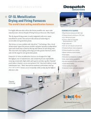
INTRODUCTION<br />
This section provides an overview of the <strong>Despatch</strong> LND Series forced air oven. The<br />
LND Series Ovens have the most effective heat distribution and the fastest processing<br />
time of any lab oven their size. Air is discharged from the left side wall of the oven and<br />
circulates through the chamber.<br />
Special Features<br />
• The sturdy construction and three inch insulation of the <strong>Despatch</strong> LND Series<br />
ovens contribute to excellent temperature uniformity.<br />
• Other special features include the following:<br />
• Unique <strong>Despatch</strong> design to combine higher fan volume of forced recirculated air<br />
with a system of perforated stainless steel walls for the ultimate in temperature<br />
uniformity.<br />
• Welded double wall construction and fiberglass insulation to reduce heat loss.<br />
Silicone rubber gaskets further minimize heat leakage.<br />
• Rapid response heater.<br />
• Scratch-resistant baked enamel exterior and stainless steel interior for easy<br />
cleaning.<br />
• Purge and maintain valves and flowmeters for creating an inert gas atmosphere<br />
in the oven chamber<br />
• Water cooling coil for dissipating heat from the oven chamber<br />
1
Specifications<br />
Dimensions<br />
Model<br />
Chamber Size<br />
in (cm)<br />
Capacity<br />
feet 3<br />
(liters)<br />
Overall Size<br />
in (cm)<br />
W D H W D H<br />
Maximum<br />
Number of<br />
Shelf<br />
Positions<br />
LND 1-42<br />
20<br />
(50)<br />
18<br />
(46)<br />
20<br />
(51)<br />
4.2<br />
(120)<br />
33<br />
(84)<br />
41<br />
(104)<br />
45<br />
(114)<br />
9<br />
LND 2-11<br />
38<br />
(96)<br />
20<br />
(50)<br />
26<br />
(66)<br />
11.0<br />
(310)<br />
54<br />
(137)<br />
40.5<br />
(103)<br />
63<br />
(160)<br />
6<br />
LND 2-24<br />
48<br />
(122)<br />
24<br />
(61)<br />
36<br />
(91)<br />
24.0<br />
(680)<br />
66<br />
(166)<br />
44.5<br />
(113)<br />
74<br />
(188)<br />
9<br />
Capacities<br />
Model LND 1-42 LND 2-11 LND 2-24<br />
Maximum Load<br />
Lbs<br />
150<br />
180<br />
300<br />
Maximum Shelf Load<br />
Lbs<br />
30<br />
60<br />
100<br />
Recirculating Fan<br />
CFM<br />
HP<br />
300<br />
1/4<br />
1,000<br />
1<br />
1,500<br />
2<br />
Approximate Weight Net<br />
Lbs.<br />
KG<br />
380<br />
173<br />
745<br />
339<br />
1,065<br />
484<br />
Approximate Shipping Weight<br />
Lbs.<br />
KG<br />
510<br />
232<br />
1,045<br />
475<br />
1,465<br />
666<br />
2
Temperature<br />
Model LND 1-42 LND 2-11 LND 2-24<br />
Time to Temperature 25°C - 100°C<br />
(approximate minutes with 25°C - 200°C<br />
no load) 25°C - 343°C<br />
6<br />
25<br />
56<br />
5<br />
14<br />
32<br />
3<br />
12<br />
30<br />
Recovery Time Door Open 1 Min. 100°C<br />
(approximate minutes with 200°C<br />
no load) 343°C<br />
Power<br />
Line voltages may vary in some geographical locations. If your line voltage is much<br />
lower than the oven voltage rating, warm up time will be longer and motors may<br />
overload or run hot. If your line voltage is higher than name plate rating, the motor may<br />
run hot and draw excessive amps.<br />
If the line voltage varies more than 10% from the oven voltage rating, some electrical<br />
components such as relays, temperature controls, etc. may operate erratically.<br />
Power Requirements<br />
Model Volts Amps Hertz Phase Heater KW<br />
LND 1-42<br />
LND 2-11<br />
LND 2-24<br />
240*<br />
208<br />
240<br />
480<br />
208<br />
240<br />
480<br />
15.6<br />
29.8<br />
26.1<br />
13.1<br />
52.4<br />
46.0<br />
23.0<br />
50/60<br />
60<br />
60<br />
60<br />
60<br />
60<br />
60<br />
* Oven designed for 240 volts (see name plate on oven) will operate satisfactorily on a<br />
minimum of 208 volts, but with a 25% reduction in heater power. If your power<br />
characteristics are lower, contact <strong>Despatch</strong> <strong>Industries</strong>. An option is available to regain<br />
the full heater power when operating on 208V.<br />
1<br />
3<br />
3<br />
3<br />
3<br />
3<br />
3<br />
3<br />
9<br />
9<br />
9<br />
16<br />
16<br />
16<br />
4
THEORY OF OPERATION<br />
This section details the function and operation of assemblies and subassemblies on the<br />
<strong>Despatch</strong> LND Series Ovens. These ovens have the most effective heat distribution<br />
system and the fastest processing time of any lab ovens their size. They are especially<br />
useful for testing, preheating, sterilizing, drying, aging and curing as well as other<br />
production applications. Horizontal airflow with precision digital control delivers uniform,<br />
fast processing. The overall result is efficient productivity under strenuous conditions.<br />
Inert Gas<br />
Figure 1. Horizontal Airflow<br />
The unique <strong>Despatch</strong> computerized design, moves forced convected heat through<br />
perforated stainless steel walls. The air is recirculated with a high volume fan.<br />
<strong>Despatch</strong> LND Series Ovens employ higher volume fans than any competitive model.<br />
The chamber can be densely loaded without interfering with the process. The LND<br />
series air delivery temperature is within 1/2° C of the number appearing on the digital<br />
display. Nitrogen intake is regulated by separate purge and maintain panel-mounted<br />
flowmeters. The cooling water flow is controlled by an adjustable valve and monitored<br />
by a flowmeter located on the rear of the oven.<br />
5
Inert Atmosphere Theory<br />
The goal of the inert atmosphere oven is to reduce oxygen concentration levels to an<br />
acceptable level. This is accomplished by injecting an inert gas into the sealed<br />
chamber. As the flow rate of inert gas into the chamber is increased, the chamber<br />
becomes pressurized and gas is exhausted out the pressure relief valve located on the<br />
back of the oven. Since oxygen is repelled by inert gas flow, the overall oxygen<br />
concentration in the chamber is reduced.<br />
However, there is a limit to the desired inert gas flow rate into the chamber. To<br />
minimize the oxygen concentration level, you must minimize the number of exhaust<br />
outlets. The only desired outlet is through the pressure relief valve. If the inert gas flow<br />
rate is too high, other exhaust outlets will be formed (usually the door seal). In this<br />
situation oxygen can penetrate back through the leak or outlet even though the chamber<br />
is pressurized. This process is called diffusion. As diffusion is minimized, oven<br />
performance is maximized.<br />
WARNING:<br />
This oven is not designed for use with<br />
flammable material. If your process<br />
involves flammable material see the LFD<br />
series.<br />
6
OVEN INSTRUCTIONS<br />
The INSTRUCTIONS section provides directions for unpacking, installation, operation<br />
and maintenance of the LND Series oven.<br />
Unpacking and Inspection<br />
Remove all packing materials and thoroughly inspect the oven for damage of any kind<br />
that could have occurred during shipment.<br />
• See whether the carton and plastic cover sheet inside carton are still in good<br />
condition.<br />
• Look at all outside surfaces and corners of the oven for scratches and dents.<br />
• Check the oven controls and indicators for normal movement, bent shafts,<br />
cracks, chips or missing parts such as knobs and lenses.<br />
• Check the door and latch for smooth operation.<br />
If there is damage that may have occurred during shipment, follow these instructions.<br />
1. Contact the shipper immediately and file a written damage claim.<br />
2. Contact <strong>Despatch</strong> <strong>Industries</strong> to report your findings and to order replacement<br />
parts for those that were damaged or missing.<br />
3. Send a copy of your filed damage claims to <strong>Despatch</strong>.<br />
4. Next, check to make sure you have received all the required materials. Your<br />
shipment should include:<br />
One (1) <strong>Despatch</strong> oven,<br />
One (1) Instruction manual,<br />
One (1) Warranty card,<br />
Two (2) Shelves<br />
5. If any of these items are missing from the packaged contents, contact <strong>Despatch</strong><br />
<strong>Industries</strong> to have the appropriate materials forwarded to you.<br />
6. Finally, to protect the warranty on your new LND Series Oven, complete the<br />
warranty card and mail it to <strong>Despatch</strong> within 15 days after receipt of the<br />
equipment.<br />
7
Set-up<br />
1. Select the location for installing your oven.<br />
The oven must have a minimum 2 inch<br />
clearance in the rear to provide proper<br />
ventilation. The oven may be placed next to<br />
another cabinet, or next to another oven, with<br />
a 3 inch clearance to insure proper ventilation.<br />
Make sure oven is level and plumb; this will<br />
assure proper heat distribution and operation<br />
of all mechanical components.<br />
WARNING:<br />
Do not use the oven in wet,<br />
corrosive or explosive<br />
atmospheres unless this oven is<br />
specifically designed for a<br />
special atmosphere.<br />
2. Connect the nitrogen supply line to the inlet located on the oven rear panel and<br />
marked nitrogen supply. The nitrogen supply to the oven must not exceed 80<br />
PSI. (40 PSI on LND 1-42)<br />
3. Check for leaks in the nitrogen supply line.<br />
a. Turn the three-way nitrogen valve<br />
switch to the OFF position.<br />
WARNING:<br />
Use only inert gases.<br />
b. Turn the PURGE flowmeter knob<br />
clockwise to the OFF position.<br />
c. Turn the MAINTAIN flowmeter knob clockwise to the OFF position.<br />
d. Open tank valve on the nitrogen supply.<br />
e. Set pressure regulator to about 40 PSI.<br />
f. Check the nitrogen plumbing for leaks with a soapy water solution.<br />
As nitrogen gas is odorless, all leaks should be<br />
stopped to prevent the possibility of suffocation<br />
in a small work area. Gas from a nitrogen leak<br />
might leak might displace much of the oxygen<br />
in the atmosphere.<br />
4. If cooling is required, install water connection<br />
for cooling coils.<br />
WARNING:<br />
All grounding and safety<br />
equipment must be in compliance<br />
with applicable codes,<br />
ordinances and accepted safe<br />
practices.<br />
8
Flowmeter<br />
Cooling Coil<br />
Vacuum<br />
Breaker<br />
Check<br />
Valve<br />
Drain<br />
3-way Valve<br />
Drain<br />
Flow Valve<br />
Cooling Water Supply<br />
Figure 2. Recommended Water Connection on <strong>Despatch</strong> LND Series Ovens<br />
a. Make drain connections at the check<br />
valve and 3-way valve.<br />
b. Connect cooling water supply to the<br />
flow valve.<br />
c. Open 3-way valve and adjust flow<br />
control valve for maximum flow.<br />
d. Check for leaks.<br />
WARNING:<br />
NEVER use the water cooling<br />
coil without a gas flow into the<br />
chamber. Not using inlet gas<br />
during cooldown creates a<br />
vacuum pressure which could<br />
cause extensive damage to the<br />
oven.<br />
CAUTION:<br />
Design the drain system to prevent operator injury from high temperature or pressure<br />
buildup. Piping must be able to withstand short periods of up to 650 F (343 C)<br />
temperatures. Drain lines should be insulated or warning labels installed that a hazard<br />
exists.<br />
WARNING:<br />
Never allow drain to be plugged as a hot oven will generate a small amount of steam when<br />
the water is first turned on. Steam burns.<br />
9
e. Adjust flowmeter for desired flow rate. Consult the following chart for<br />
cooldown rates.<br />
f. Close 3-way valve. Make sure check valve is working properly by<br />
monitoring water flow back through the cooling coil and out the drain port<br />
of the 3-way valve.<br />
300<br />
200<br />
LND2-24<br />
LND1-42<br />
100<br />
0<br />
0 10 20 30 40 50<br />
Time<br />
(minutes)<br />
LND2-11<br />
Figure 3. Cool Down Rate with Water Cooling Coil (unit without a load).<br />
NOTE:<br />
Cooldown rates are approximate. Load mass, inert gas flow and exhaust rates affect cool<br />
down times.<br />
5. Identify correct power source indicated on the specification plate.<br />
6. On larger units, remove the control panel and the filter panel to expose the<br />
equipment mounting area.<br />
7. Hard wire oven directly to the electric supply. On larger units the line connection<br />
is located on the equipment mounting panel.<br />
10
Operating<br />
Users and operators of this oven must comply with<br />
operating procedures and training of operating<br />
personnel as required by the Occupational Safety and<br />
Health Act (OSHA) of 1970, Section 5 and relevant<br />
safety standards, and other safety rules and<br />
regulations of state and local governments. Refer to<br />
the relevant safety standards in OSHA and National<br />
Fire Protection Association (NFPA), Section 86 of<br />
1990.<br />
WARNING:<br />
Do not use oven in wet,<br />
corrosive or explosive<br />
atmospheres unless this oven is<br />
specifically designed for a<br />
special atmosphere.<br />
Loading the Oven<br />
<strong>Despatch</strong> <strong>Industries</strong> cannot be responsible for either the process or process<br />
temperature used, or for the quality of the product being processed. It is the<br />
responsibility of the purchaser and operator to see that the product undergoing<br />
processing in a <strong>Despatch</strong> oven is adequately protected from damage.<br />
Carefully following the instructions in this manual will help the purchaser and operator in<br />
fulfilling that responsibility.<br />
When loading the oven avoid spills of anything onto the heater elements or onto the<br />
floor of the oven. Do not place the load on the oven floor plate. This may cause the<br />
load to heat unevenly and the weight may cause<br />
shorting out of the heater elements. Use the shelves<br />
provided.<br />
The two shelves are designed to be pulled out about<br />
half way without tipping. The support capacity of the<br />
shelves is listed in the Capacities Table in the<br />
Specifications section in this manual. Do not<br />
overload the shelves.<br />
WARNING:<br />
Do not use flammable solvent<br />
or other flammable material in<br />
this oven. Do not process<br />
closed containers of any<br />
substance because they may<br />
explode under heat.<br />
Distribute the workload evenly so that airflow is not restricted. Do not overfill your oven.<br />
The workload should not take up more than two-thirds of any dimension of the inside<br />
cavity.<br />
11
Pre-Startup Checklist<br />
• Know the system. Read this manual carefully. Make use of its instructions and<br />
explanations. Safe, continuous, satisfactory, trouble-free operation depends<br />
primarily on your understanding of the system and your willingness to keep all<br />
parts in proper operating condition.<br />
• Check line voltage. Voltage must correspond to nameplate requirements of<br />
motors and controls. Refer to the section on power connections in the<br />
INTRODUCTION of this manual.<br />
• Fresh air and exhaust. Do not be careless about restrictions in and around the<br />
fresh air and exhaust openings and stacks. Under no condition permit them to<br />
become so filled with dirt that they appreciably reduce the air quantity. The<br />
proper ventilation clearances should be fulfilled at all times. Refer to the Set-up<br />
instructions in this manual.<br />
• Helpful hints<br />
For drying ovens, open vent to prevent buildup of moisture.<br />
For sample heating, close the vent when no ventilation is required.<br />
Startup<br />
For fastest oven heat-up time, close the fresh-air vent. After the desired temperature is<br />
reached, the vent may be adjusted as needed.<br />
1. Start Fan.<br />
a. Open oven door.<br />
b. Press Power switch to the On position. You will hear the recirculating fan<br />
start.<br />
c. Shut oven door.<br />
d. Check that the control display turns on.<br />
2. Adjust nitrogen flow rate.<br />
a. Determine the desired oxygen level.<br />
b. Use the following chart to determine the time to achieve the desired<br />
oxygen level.<br />
12
c. Turn the nitrogen valve switch to the PURGE position for the time to<br />
achieve oxygen level as determined in step 2b.<br />
20<br />
16<br />
12<br />
8<br />
4<br />
0<br />
0 4 8 12 16 20 24 28 32<br />
Figure 4. Oxygen Level vs. Time at Maximum SCFH Purge Flow<br />
d. When the purge is complete, turn the nitrogen valve switch to the<br />
MAINTAIN position.<br />
e. Use the charts on the next page to determine the MAINTAIN flowmeter<br />
value to maintain the oxygen stabilization level.<br />
f. Adjust the MAINTAIN flowmeter to the value determined in step 2e.<br />
3. Operate the temperature control as desired by following the control operation<br />
instructions that follow.<br />
13
Figure 5. Nitrogen Leakage Rate vs. Oven Pressure<br />
Figure 6. Oxygen Stabilization Level vs. Flow of Nitrogen<br />
14
Automatic Nitrogen and Water Cooling<br />
Your oven may be fitted with optional automatic water cooling and/or nitrogen control<br />
features. These features replace the manual on/off valves with solenoid valves which<br />
can be operated either by switches in the control panel or programmed event outputs on<br />
the temperature control instrument.<br />
The additional switches in the control panel have AUTO and MANUAL positions.<br />
Placing the switch in MANUAL energizes the appropriate solenoid valve. Leaving the<br />
switch in the AUTO position allows the solenoid valve to be operated by the control<br />
event outputs.<br />
Refer to the following section on the control instrument for more information on<br />
programming the event outputs. The standard configuration for these optional features<br />
is for event relay 1 to operate water cooling, event relay 3 to operate nitrogen purge,<br />
and event relay 4 to operate nitrogen maintain. In addition, if the optional door lock<br />
feature is also installed, it will be in the locked position any time the nitrogen maintain<br />
solenoid is energized.<br />
Typically, the control is programmed so that the purge and maintain valves are<br />
energized at the beginning of a program in a segment of long enough duration to purge<br />
the oven (see the oxygen level chart discussed earlier). The next program segment then<br />
de-energizes the purge valve while leaving the maintain valve energized. The maintain<br />
valve should be left energized for as long as the nitrogen level is desired to be<br />
maintained.<br />
The water cooling solenoid valve is energized in the last segment(s) of the program to<br />
bring the chamber temperature down to a safe unloading temperature.<br />
15
CONTROL<br />
The special features of the Protocol Plus TM control include:<br />
PID tuning<br />
Ramp/Soak programming of up to 64 segments<br />
Segment looping and profile linking<br />
Built-in manual reset high limit control<br />
Built-in process timer<br />
Dedicated LED display for process temperature<br />
Multi-purpose two-line LCD display with backlight<br />
Auto-tuning<br />
Security access<br />
Process temperature retransmission signal<br />
Digital inputs for remote profile control<br />
Real time clock<br />
Optional relay outputs for events, alarms, or end-of-cycle signal<br />
Optional RS232/RS422/RS485 MODBUS communications<br />
Theory of Control Operation<br />
The Protocol Plus is a modular microprocessor based digital temperature controller. The<br />
Protocol Plus operates as a dual functioning controller/high limit instrument. The control<br />
portion utilizes a time-proportioning voltage signal to control heating devices with<br />
minimal temperature fluctuations.<br />
The high limit portion protects the product and/or the oven from overheating. If the<br />
product being processed has a critical high temperature limit, the high limit setpoint<br />
should be set to a temperature somewhat below the temperature at which the product<br />
could be damaged. If the product does not have a critical high temperature limit, the<br />
high limit setpoint should be set 5 to 15 degrees higher than the maximum programmed<br />
setpoint at which the oven will operate.<br />
16
Protocol Plus Faceplate and Wiring Diagram<br />
17
Operating Modes<br />
The Protocol Plus control has five modes of operation available:<br />
Stopped Mode:<br />
<strong>Manual</strong> Mode:<br />
Timer Mode:<br />
Profile Mode:<br />
All control and relay outputs are off. Stopped Mode is integrated<br />
into each of the following four modes of operation.<br />
Control operates as a single setpoint control until Stopped mode is<br />
accessed<br />
Control operates as a single setpoint control until preset time period<br />
has expired.<br />
Control operates as a ramp/soak profiling control until the end of<br />
the profile. 8 profiles are available with up to 8 ramp/soak segments<br />
in each profile.<br />
Auto Start Mode: Control may automatically start <strong>Manual</strong>, Timer, or Profile mode<br />
based on a preset time and day.<br />
The optional event outputs can be utilized during <strong>Manual</strong>, Timer, or Profile modes.<br />
Setup Mode<br />
The control has a Setup Mode which provides access to control configuration and<br />
programming of profiles. The Setup Mode contains ten separate electronic Pages where<br />
the configuration and programming parameters (Menu items) are found. The Setup<br />
Mode Pages are described in detail elsewhere in this manual.<br />
Fast Start Mode<br />
The Protocol Plus control has the ability to automatically start an operating mode when<br />
power is applied. This feature may be useful if the same mode of operation is used<br />
everyday. The user can turn on the power and the oven will start the desired process<br />
automatically. The Fast Start Mode is controlled by the Power-Up Start parameters on<br />
the Control page (see Setup Mode).<br />
18
High Limit<br />
The control has an integrated high limit function which will disable the heater output<br />
when tripped. If the high limit does trip, the relay will need to be manually reset. When<br />
the high limit relay is tripped, the Hi-Limit indicator will be lit. Allow the oven to cool<br />
several degrees (or increase the high limit setpoint) and then press the Reset key. The<br />
indicator will turn off.<br />
High-Limit temperature readout is provided on LCD Line #2 in all Modes (Stop, Run,<br />
Hold, and Standby) except Setup Mode. High-Limit temperature is displayed for 10<br />
seconds, alternating with current Mode and Status display for 10 seconds.<br />
The control will not allow the high limit setpoint to be set below the current setpoint<br />
value.<br />
Indicators<br />
The Protocol Plus control has 12 indicating LEDs that provide operational information to<br />
the user.<br />
Power LED: Indicates that power is supplied to the instrument.<br />
Heater LED: Indicates that the heater output is active.<br />
Profile LED: Indicates that the Profile Mode is in operation.<br />
Timer LED: Indicates that the Timer Mode is in operation.<br />
<strong>Manual</strong> LED: Indicates that the <strong>Manual</strong> Mode is in operation.<br />
Cycle Complete LED: Indicates that the control is in Stopped mode.<br />
Hi-Limit Alarm LED: Indicates that the high limit relay has tripped<br />
(de-energized).<br />
Soak Alarm LED: Indicates that the guaranteed soak deviation is in alarm<br />
condition.<br />
Outputs 1 through 4: Indicate that the optional relay outputs are in the ON<br />
state. These outputs may be configured as timed event outputs, process<br />
temperature trip point outputs, alarm outputs, or as an end of cycle relay output.<br />
The ON state can be configured as energized or de-energized.<br />
19
Displays<br />
The Protocol Plus control has two displays. A dedicated LED upper display shows the<br />
oven temperature. A two-line LCD lower display provides information on control status,<br />
high limit temperature, and allows changes to be made to the control settings.<br />
Key Functions<br />
The Protocol Plus control has seven keys that provide operation.<br />
Select key: Press to select mode of operation. In Setup Mode, to select profile<br />
number or relay. In Profile/Run Mode, press simultaneously with the UP key to<br />
advance a segment.<br />
Run/Hold key: Press to activate a mode of operation. If a Profile (or Timer)<br />
Mode is running, pressing the Run/Hold key will place the Profile (or Timer) in<br />
Hold status. A subsequent press will resume the Profile (Timer).<br />
Stop key: Press to stop any mode of operation.<br />
Page/Reset key: While in Setup Mode, press to access different Pages of<br />
configuration, Press this key to silence an alarm if the instrument alarm sounds<br />
during operation. In an operating mode, if an alarm or error condition occurs,<br />
press this key to return the instrument to normal operation once the condition is<br />
cleared.<br />
Menu/View key: While running any operating mode, pressing this key will<br />
display the high limit setpoint. While in Setup Mode, pressing this key will provide<br />
access to each Menu parameter.<br />
keys: Press these keys to adjust parameter settings. In Profile/Stopped<br />
Mode, press to select profile to run. In Profile/Run Mode, press key<br />
simultaneously with the Select key to force the program to advance one<br />
segment.<br />
20
Outputs<br />
The Protocol Plus control has seven different outputs available.<br />
Heating output: The control output is a DC voltage open-collector output which<br />
is time-proportioned and designed to control a heat control device such as a solid<br />
state relay.<br />
High limit: The high limit output is a form C relay which is energized under<br />
normal operating conditions. If the control senses a temperature higher than the<br />
high limit setpoint, or if there is a sensor error, the high limit relay will de-energize<br />
until the condition is cleared and the Reset key is pressed. When the high limit<br />
relay is de-energized, the heater is disabled.<br />
Retransmission: The retransmission output is a DC 1 to 5 volt or 4 to 20 ma<br />
(DC) signal that is proportional to the process temperature. The signal can be an<br />
input to other devices such as a chart recorder.<br />
Relay (four optional outputs): The four form A dry contact relay outputs can be<br />
configured to function as alarms, events, or end of cycle. These outputs can be<br />
utilized in <strong>Manual</strong>, Timer, or Profile Mode.<br />
Layout for Optional Components<br />
21
Relay (Continued)<br />
Use the Relay Card Optional Ay p/n 144562 to add relays to the standard controller.<br />
Each relay card contains two relays (maximum of two cards Ay’s allowed).<br />
Communication<br />
The Protocol Plus control has optional MODBUS communication available which can<br />
communicate via RS232, RS422, or RS485 to a computer. See communications option<br />
assembly p/n 161957 for board and cable assembly. Please refer to the MODBUS<br />
communications manual which comes with this option.<br />
Optional Software<br />
The Protocol Manager program allows the operator to start/stop multiple ovens (32<br />
maximum) from a personal computer. A data log can also be used to record process<br />
information (p.n. 140008).<br />
22
INSTRUCTIONS<br />
Start-Up<br />
These instructions are provided as a quick reference for operating the Protocol Plus<br />
control. If the Profile Mode is to be used, or the configuration of the control needs to be<br />
changed, please refer to the Setup Mode instructions before operating the control. For<br />
more detailed operating instructions refer to the Operation instructions for the mode you<br />
wish to use.<br />
Upon initial power-up the control is in <strong>Manual</strong>/Stopped Mode (unless the Autostart or<br />
Fast Start Modes are active). To activate any operating mode from Stopped Mode,<br />
press the Select key until the desired mode is displayed, then press the Run key. If the<br />
proper Profile number is not displayed when the Profile Mode is accessed, press the<br />
or keys until the desired Profile number is displayed, then press the Run key. If no<br />
profile numbers can be displayed (display only reads NONE) then no profiles are<br />
currently programmed (see Setup Mode).<br />
The Hi-limit thermocouple actual temperature reading is displayed, when the lower LCD<br />
display reads HL Temp. Note: This is not a error message.<br />
The temperature setpoint can be adjusted while <strong>Manual</strong> or Timer Mode is running by<br />
pressing the UP or DOWN key.<br />
To momentarily hold the Timer or Profile Mode, press the Hold key. To continue the<br />
Timer or Profile Mode, press the Run key.<br />
To return to Stopped Mode at any time, press the Stop key and the cycle complete LED<br />
will illuminate.<br />
Note that the control can be configured to automatically activate <strong>Manual</strong>, Timer or<br />
Profile Mode when power is applied (power switch turned on). See Control Page in the<br />
Setup Mode to utilize the Fast Start mode.<br />
23
Operation<br />
<strong>Manual</strong> Mode<br />
Press the Select key until <strong>Manual</strong> is displayed (note you can press the Run key at any<br />
time to activate <strong>Manual</strong> Mode).<br />
1. Press the Menu key to display the Process Temperature Setpoint (setpt). You<br />
can change the Setpoint with the keys.<br />
Note: If the SPChange parameter on the Enable page in Setup Mode has been<br />
set to DISABLED, it must be changed to ENABLED before any changes to the<br />
process temperature and high limit setpoints can be made.<br />
2. Press the Menu key a second time to display current high limit setpoint (Hi-Lim<br />
SP). The value can be adjusted by pressing the keys. If Band is displayed,<br />
the high limit band feature is activated (see Control page) and the high limit can<br />
not be adjusted.<br />
3. (optional feature) Press the Menu key a third time to display Event1. Press the<br />
key to turn on the event or to turn off the event. Repeat for all events which<br />
are enabled (up to 4).<br />
4. To start <strong>Manual</strong> Mode, press the Run key.<br />
The display will change from Stop to Run. To return to Stopped Mode, press the<br />
Stop key. While in operation, the process setpoint can be adjusted by using the<br />
keys to change the value while the mode is running. Pressing the Menu key<br />
will display the High Limit Setpoint (HLSP) setting.<br />
If changes to the high limit setpoint or event output configuration are needed, they must<br />
be done from the stopped mode.<br />
24
Timer Mode<br />
1. Press the Select key until Timer is displayed (note you can press the Run key at<br />
any time to activate Timer Mode).<br />
2. Press the Menu key to display the Process Temperature Setpoint (Setpt). You<br />
can change the Setpoint with the keys.<br />
Note that if the SPChange parameter on the Enable page in Setup Mode has<br />
been set to DISABLED, it must be changed to ENABLED before any changes to<br />
the process temperature and high limit setpoints can be made.<br />
3. Press the Menu key a second time to display current high limit setpoint (Hi-lim<br />
SP). The value can be adjusted by pressing the keys. If Band is displayed,<br />
the high limit band feature is activated (see Control page) and the high limit can<br />
not be adjusted.<br />
4. Press the Menu key a third time to display Time Set. You can change the time<br />
setting with the keys.<br />
5. (optional feature) Press the Menu key a fourth time to display Event1. Press the<br />
key to turn on the event or to turn off the event. Repeat for all events which<br />
are enabled (up to 4).<br />
6. Press the Menu key a fifth time to display the current guaranteed soak band<br />
(TmrGuarSoak) value. If the process temperature deviates from the setpoint by<br />
more than this value, the timer is placed in a hold condition. The timer continues<br />
when the process temperature falls within range. Reference the Quick<br />
Reference and Default Values section for available settings.<br />
7. To start Timer Mode, press the Run key.<br />
The display will change from Stop to Run and the time remaining will be<br />
displayed. To return to Stopped Mode, press the Stop key. While in operation,<br />
the process setpoint can be adjusted by using the keys to change the value<br />
while the mode is running. Pressing the Menu key will display the High Limit<br />
Setpoint.<br />
Pressing the Run/Hold key while the Timer Mode is in operation will put the control in<br />
Hold status. The Timer LED will flash to indicate the held status. Press the Run/Hold<br />
key again to continue timing. The Timer LED will return to lit status.<br />
25
Profile Mode<br />
1. Press the Select key until Profile is displayed. “None” may be displayed if a<br />
profile has not been selected or no profiles entered.<br />
2. Press the key to display the desired profile to run.<br />
3. To start Profile Mode, press the Run key.<br />
The display will change from Stop to Run and the segment time remaining,<br />
Temperature Setpoint, Profile #, along with the current segment number, will be<br />
displayed. To return to Stopped Mode, press the Stop key.<br />
Pressing the Run/Hold key while the Profile Mode is in operation will put the control in<br />
Hold status. Press the Run/Hold key again to continue the mode. The Profile LED will<br />
flash to indicate the hold status.<br />
To advance to the next segment while running a profile, press the Select and UP arrow<br />
keys at the same time.<br />
If Link To is set to Standby in the Program Page, at the End of Program/Profile,<br />
1. Cycle Complete LED indication goes ON.<br />
2. Controller beeps if End of Cycle beep is enabled.<br />
3. Heater/control output keeps controlling oven temperature at last Soak setpoint.<br />
4. All events programmed (if relay cards installed and programmed as an event) for<br />
the last Soak Segment stays active.<br />
Note that ramping down too fast may cause the high limit relay to trip unexpectedly if<br />
the high limit band feature is used. This can be avoided by using a separate cooling<br />
profile that does not utilized the high limit band and then jumping to that profile to<br />
perform rapid cooling.<br />
Auto Start Mode<br />
The Auto Start Mode allows the control to start <strong>Manual</strong>, Timer, or Profile mode<br />
automatically at a preset time and day. See the Auto Start Page in Setup Mode for the<br />
time, day, and operating mode settings.<br />
To activate the Auto Start Mode,<br />
1. On Auto Start page, Enable is set to Yes.<br />
2. LCD reads Active on line 1 in Auto Start Mode.<br />
3. On Auto Start page Enable set to No, will deactivate Auto Start Mode.<br />
26
Note that once you activate Auto Start, you can continue to use all operating modes as<br />
normal. If an operating mode is running at the time of a preset Auto Start function, and<br />
Auto Start is activated, the existing operating mode will override the auto Start function<br />
and the Auto Start will not turn on.<br />
Note: All process Set to Run in Auto Start Mode must be at least one minute long for all<br />
Run Modes (<strong>Manual</strong>, Timer, and Profile).<br />
Setup Mode<br />
Configuration of the control and programming of the ramp/soak profiles must be done in<br />
the Setup Mode. To access Setup Mode, the control must first be in Stopped Mode.<br />
1. Press the Select key until Setup is displayed.<br />
2. Press the Page key and Security will be displayed.<br />
3. Press the Menu key and Password will also be displayed. Use the keys to<br />
enter the proper password.<br />
4. Once the proper password is displayed, press the Page key twice to enter the<br />
Setup Mode.<br />
To exit Setup Mode, press and hold the Page key for three seconds.<br />
The control has two levels of password-protected security. Level one provides access<br />
only to those menu pages that are enabled on the Enable page. Level two provides<br />
access to all menu pages, including the Enable page. The default security password<br />
values are 1 for level one and 2 for level two.<br />
If an improper password has been entered, the control will remain at the Security<br />
display. To enter the proper password, press the Menu key. To exit Setup Mode, press<br />
and hold the Page key for three seconds.<br />
Mapping of the Setup Mode is provided in the following sections. To access each<br />
parameter Page, which are described in detail in the following sections, press the Page<br />
key until the desired page heading is displayed. Press the Menu key to access each<br />
Menu parameter. Press the keys to change Menu parameter settings.<br />
Refer to the Quick Reference and Default Values section for available settings for each<br />
Menu parameter.<br />
Press the Page key to continue with each Page, or press and hold the Page key for<br />
three seconds to exit Setup Mode.<br />
27
Instructions for Setup Mode Pages<br />
Program Page<br />
Programming of the profiles is provided on the Program Page. Eight profiles are<br />
available with up to eight ramp and soak segments per profile.<br />
If the optional relay outputs are installed, they must be configured as alarms or events<br />
on the Relay Outputs Page before they can be utilized. If configured as event outputs,<br />
these relays can be used as time or temperature events.<br />
When entering the Program Page, press the Select key to select the profile you wish to<br />
enter/edit, then press the Menu key. The first parameter (Profile #, Segment 1, Ramp<br />
Time) will display. Adjust the time value with the keys. Once the proper value is<br />
displayed, press the Menu key to continue. Continue with the Menu key to adjust/view<br />
each parameter.<br />
If the ramp time value of the current segment is left at 0:00, the next press of the Menu<br />
key will advance the control to the High Limit Setpoint parameter for that profile.<br />
Continue entering / verifying all parameters until you get to the last parameter<br />
(Guaranteed Soak Band). Once all parameters have been properly entered, press the<br />
Page key to return to the top of the Profile Page. You can press the Select key to<br />
enter/edit another profile, press the Page key to access another page, or press and hold<br />
the Page key to exit Setup mode.<br />
While editing any profile, pressing the Select key will advance the control to the time<br />
value for the next segment, until the last segment has been reached. This allows faster<br />
editing of the profile rather than pressing the Menu key to advance past each<br />
parameter.<br />
If Link To is set to Standby in the Program Page, at the End of Program/Profile,<br />
1. Cycle Complete LED indication goes ON.<br />
2. Controller beeps if End of Cycle beep is enabled.<br />
3. Heater/control output keeps controlling oven temperature at last Soak setpoint.<br />
4. All events programmed (if relay cards installed and programmed as an event)<br />
for the last Soak Segment stays active.<br />
To run a profile indefinitely, link the profile to itself.<br />
28
Menu Item Display Description<br />
Ramp Time Seg 1 Pro-1 Seg-1 Ramp Time Ramp time for segment 1 of profile<br />
Event 1 Set Value* Pro-1 Seg-1 Ramp Event 1 Event 1 setting for segment 1 ramp of profile<br />
Event 2 Set Value* Pro-1 Seg-1 Ramp Event 2 Event 2 setting for segment 1 ramp of profile<br />
Event 3 Set Value* Pro-1 Seg-1 Ramp Event 3 Event 3 setting for segment 1 ramp of profile<br />
Event 4 Set Value* Pro-1 Seg-1 Ramp Event 4 Event 4 setting for segment 1 ramp of profile<br />
Soak Temp Seg 1 Pro-1 Seg 1 Soak Temp Soak temperature for segment 1 of profile<br />
Soak Time Seg 1 Pro-1 Seg 1 Soak Time Soak time for segment 1 of profile<br />
Event 1 Set Value* Pro-1 Seg-1 Soak Event 1 Event 1 setting for segment 1 soak of profile<br />
Event 2 Set Value* Pro-1 Seg-1 Soak Event 2 Event 2 setting for segment 1 soak of profile<br />
Event 3 Set Value* Pro-1 Seg-1 Soak Event 3 Event 3 setting for segment 1 soak of profile<br />
Event 4 Set Value* Pro-1 Seg-1 Soak Event 4 Event 4 setting for segment 1 soak of profile<br />
(repeat for segments 2-8, until ramp or soak time = 00:00)<br />
High Limit Setpoint Pro-1 Hi-Lim SP High limit setpoint for profile**<br />
Loop From Pro-1 Loop From Seg To start a loop action in a profile<br />
Loop To Pro-1 Loop To Seg To end a loop action in a profile<br />
Loop Count Pro-1 Loop Number Number of times to execute loop<br />
Profile Link Pro-1 Link To Pro To jump from this profile to another<br />
Guaranteed Soak Pro-1 Guar Band Guaranteed soak band for profile<br />
See the definitions on the following pages for parameter ranges.<br />
* only available if optional relay outputs are installed (repeat all for profiles 2-8)<br />
** Set to Band to use the high limit band feature<br />
29
Profile #<br />
Segment#<br />
Ramp Time<br />
EV1 through 4<br />
Soak Temp.<br />
Soak Time<br />
EV1 through 4<br />
Hi Limit SP<br />
Loop From<br />
Loop To<br />
There are eight profiles available.<br />
Recipe segments 1 through 8 may be programmed, each with its own<br />
set of events, ramp and soak times, and soak temperature.<br />
The time required to ramp from one setpoint up to another setpoint.<br />
Values between 0 and 99:59 are allowable. In the Protocol Plus<br />
controller, the profile ramp and soak times are stored without units.<br />
Units are set as either hours and minutes (HH:MM) or minutes and<br />
seconds (MM:SS). The setpoint will automatically increment from the<br />
actual temperature to the soak temperature.<br />
From 1 to 4 events may be programmed into the ramp time portion of<br />
each segment here. These typically involve actuating/disabling relays<br />
to close/open valves or perform other relay-controlled functions.<br />
NOTE: These will only actuate when the controller has the relay cards<br />
installed and programmed for an event.<br />
The temperature setpoint of a particular segment is entered here; it<br />
can range from -18 to 540 degrees C (0 to 1000 degrees F).<br />
The duration of soak is entered here; the value can range from 0 to<br />
99:59.<br />
From 1 to 4 events may be programmed into the soak portion of each<br />
segment here. These typically involve actuating/disabling relays to<br />
close/open valves or perform other relay-controlled functions. NOTE:<br />
These will only actuate when the controller has the relay cards<br />
installed and programmed for an event.<br />
The high limit setpoint may be entered here; if the temperature<br />
exceeds this value, the hi-limit will alarm and shut off the heater.<br />
Values are No, Seg-1 to Seg-8.<br />
Values are No, Seg-1 to Seg-8.<br />
Loop Number Values are 0 - 99.<br />
These values enable the operator to jump from a certain step to<br />
another step of the recipe a preset number of times.<br />
Profile Link<br />
Guaranteed<br />
Soak Band<br />
Values are STANDBY/STOP/HOLD/1 - 8. When the profile ends, the<br />
profile can hold the temperature setpoint while keeping the events<br />
active, turn the heater off, hold the temperature setpoint at the end of<br />
the profile, or jump to another specified profile.<br />
If the process temperature deviates from the setpoint by more than<br />
this value, the soak timer is placed in a hold condition. The timer<br />
continues when the process temperature falls within range.<br />
30
Sample Profile<br />
Programming Table<br />
Profile Number____1______ Profile Name__________<br />
Segment<br />
Time Events Temp-<br />
Time<br />
Events<br />
Ramp<br />
Soak<br />
1 2 3 4 erature<br />
1 2 3 4<br />
1 01h00 100 01h00<br />
2 02h00 50 00h01<br />
3 00h00<br />
4<br />
5<br />
6<br />
7<br />
8<br />
High Limit Setpoint 115<br />
Loop From Seg<br />
Loop To Seg<br />
No<br />
No<br />
Loop Number 0<br />
Link To Pro<br />
No<br />
Guar Soak Band 10<br />
31
Auto Start Page<br />
The Auto Start Page can be configured to automatically start <strong>Manual</strong>, Timer or Profile<br />
Mode at a specified time and day. Note that if Auto Start Enable is set to Yes in the<br />
Setup Mode, the Auto Start feature is not turned on - it is available to the operator to be<br />
activated in Stopped Mode.<br />
To configure the Auto Start feature:<br />
1. Access the Setup Mode.<br />
2. Press the Page key until Auto Start is displayed.<br />
3. Press the Menu key. If there is no change in the display, the controller may not<br />
have the realtime clock option.<br />
4. Set Auto Start Enable to Yes.<br />
5. Using the Menu key, scroll through the options available and use the keys<br />
to set the mode desired for each day of the week. You may select from <strong>Manual</strong>,<br />
Timer, or Profile 1 through 8.<br />
6. When the mode is set press the Menu key.<br />
7. Enter the time of day you wish the mode to activate.<br />
8. Continue through the rest of the week by pressing the Menu key, or press the<br />
Page key when done.<br />
One Auto Start mode can be set for each day of the week. Exit the Setup mode by<br />
pressing and holding the Page key for three seconds. Press the Select key until Auto<br />
Start is displayed. Make sure the correct time and day is displayed. If not proper, set it<br />
to the correct time on the Real Time Clock Page in the Setup mode.<br />
To activate the Auto Start Mode,<br />
1. On Auto Start page, Enable is set to Yes.<br />
2. LCD reads Active on Line 1 in Auto Start Mode.<br />
3. On Auto Start page Enable set to No, will deactivate Auto Start Mode.<br />
Note that once you activate Auto Start, you can continue to use all operating modes as<br />
normal. If an operating mode is running at the time of a preset Auto Start function, and<br />
Auto Start is activated, the existing operating mode will override the Auto Start function<br />
and the Auto Start will not turn on.<br />
Note: All process Set to Run in Auto Start Mode must be at least one minute long for all<br />
Run Modes (<strong>Manual</strong>, Timer, and Profile).<br />
32
Menu Item Display Description Range<br />
Enable<br />
Autostart<br />
Sunday<br />
mode<br />
Sunday<br />
time<br />
Monday<br />
mode<br />
Monday<br />
time<br />
Tuesday<br />
mode<br />
Tuesday<br />
time<br />
Wednesday<br />
mode<br />
Wednesday<br />
time<br />
Thursday<br />
mode<br />
Thursday<br />
time<br />
Friday<br />
mode<br />
Friday time<br />
Saturday<br />
mode<br />
Saturday<br />
time<br />
Auto Start Enable<br />
Auto Start Sun<br />
Mode<br />
Auto Start Sun<br />
Time<br />
Auto Start Mon<br />
Mode<br />
Auto Start Mon<br />
Time<br />
Auto Start Tue<br />
Mode<br />
Auto Start Tue<br />
Time<br />
Auto Start Wed<br />
Mode<br />
Auto Start Wed<br />
Time<br />
Auto Start Thu<br />
Mode<br />
Auto Start Thu<br />
Time<br />
Auto Start Fri<br />
Mode<br />
Auto Start Fri<br />
Time<br />
Auto Start Sat<br />
Mode<br />
Auto Start Sat<br />
Time<br />
Enable (yes) or disable (no) the<br />
Autostart function<br />
Set mode on Sunday to activate<br />
Set time on Sunday for mode to<br />
activate<br />
Set mode on Monday to activate<br />
Set time on Monday for mode to<br />
activate<br />
Set mode on Tuesday to activate<br />
Set time on Tuesday for mode to<br />
activate<br />
Set mode on Wednesday to<br />
activate<br />
Set time on Wednesday for mode<br />
to activate<br />
Set mode on Thursday to activate<br />
Set time on Thursday for mode to<br />
activate<br />
Set mode on Friday to activate<br />
Set time on Friday for mode to<br />
activate<br />
Set mode on Saturday to activate<br />
Set time on Saturday for mode to<br />
activate<br />
No, Yes<br />
Off, <strong>Manual</strong>, Timer, Pro-1 to Pro-8<br />
00:00 to 23:59<br />
Off, <strong>Manual</strong>, Timer, Pro-1 to Pro-8<br />
00:00 to 23:59<br />
Off, <strong>Manual</strong>, Timer, Pro-1 to Pro-8<br />
00:00 to 23:59<br />
Off, <strong>Manual</strong>, Timer, Pro-1 to Pro-8<br />
00:00 to 23:59<br />
Off, <strong>Manual</strong>, Timer, Pro-1 to Pro-8<br />
00:00 to 23:59<br />
Off, <strong>Manual</strong>, Timer, Pro-1 to Pro-8<br />
00:00 to 23:59<br />
Off, <strong>Manual</strong>, Timer, Pro-1 to Pro-8<br />
00:00 to 23:59<br />
33
PID Page<br />
The PID Page contains parameters which control the response to the setpoint and<br />
process variable input. To access the PID Page, enter the Setup Mode. Press the Page<br />
key until PID is displayed. Press the Menu key. Each parameter can be changed by<br />
pressing the Menu key until the desired parameter is displayed, and then pressing the<br />
keys to change the value.<br />
Menu Item Display Description Range<br />
Display units PID Temp Unit Set display units to °C or °F °C or °F<br />
Proportional<br />
band<br />
Integral reset<br />
Derivative<br />
Rate<br />
PID Prop Band Set proportional band for tuning 1 to 56°C (1 to 100°F)<br />
PID<br />
Reset/Rep/Min<br />
Set integral reset for tuning<br />
0.0 to 100 seconds/repeat<br />
PID Rate In Sec Set derivative rate for tuning 0.0 to 500 seconds<br />
AutoTune PID AutoTune Enable auto tuning function Disable, Enable<br />
The AutoTune parameter disables or enables the AutoTune function. To utilize<br />
AutoTuning:<br />
1. Access the Setup Mode.<br />
2. Press the Page key until the display reads AutoTune. Press the key to enable<br />
the AutoTune.<br />
3. Press the Page key for three seconds to exit Setup Mode.<br />
4. Cycle power to the instrument.<br />
5. Set <strong>Manual</strong> Mode to run. The display will alternately display AutoTune and<br />
<strong>Manual</strong>.<br />
If the <strong>Manual</strong> Mode setpoint is less than 50 degrees higher than the actual process<br />
temperature, the AutoTune function will create an error condition. This can be cleared<br />
by either cooling off the process temperature or increasing the setpoint until there is<br />
more than 50 degrees between them. Once the AutoTune function is allowed to<br />
complete tuning, the AutoTune parameter will disable by itself.<br />
If you wish to cancel the AutoTune function, press the STOP key, access the PID page<br />
in Setup Mode, and set the AutoTune parameter to Disable.<br />
34
Control Page<br />
The Control Page contains various parameters which control miscellaneous functions.<br />
To access the Control Page, enter the Setup Mode. Press the Page key until Control is<br />
displayed. Press the Menu key. Each parameter can be changed by pressing the Menu<br />
key until the desired parameter is displayed, and then pressing the keys to change<br />
the value.<br />
Menu Item Display Description Range<br />
Cycle Time<br />
High limit<br />
setpoint<br />
High limit<br />
band<br />
Power fail<br />
recovery<br />
Recovery<br />
time limit<br />
Powerup<br />
start enable<br />
Powerup<br />
Start Mode<br />
Hysteresis<br />
Process out<br />
low<br />
Process out<br />
high<br />
Time scale<br />
Key press<br />
beep<br />
End of cycle<br />
beep<br />
Alarm beep<br />
Control Cycle<br />
Time Sec<br />
Set cycle time in seconds for<br />
control output<br />
1 to 60 seconds<br />
Control Hi-Lim Maximum value for all high limit MinHiLimSP - MaxHiLimSP*<br />
SP***<br />
setpoints<br />
Control Hi-Lim If=0, high limit setpoint= Control Off, 3°C to 11°C (5°F to 20°F)<br />
Band<br />
Hi-Lim SP If>0, high limit<br />
setpoint= Control SP* + Band<br />
Control PwrFRec Controls response to loss of Stop, Restart, Hold, Resume<br />
power<br />
Control PFRTime Control aborts to Stopped mode if 00m00s to 99m59s<br />
power is lost for time period<br />
longer then set value<br />
ControlPwrUpStrt Allows mode to automatically Disable, Enable<br />
start when power is first applied<br />
Control StrtMode Operating mode for powerup start Off, <strong>Manual</strong>, Timer, Pro-1 to Pro-8<br />
Control<br />
Hysteresis<br />
Control<br />
RetOutLo<br />
Control RetOutHi<br />
Control<br />
TimeScale<br />
Control KeyBeep<br />
Control<br />
EOCBeep<br />
Control<br />
AlarmBeep<br />
Hysteresis for all alarms and<br />
temperature events<br />
Process value for retransmit<br />
output = 1VDC<br />
Process value for retransmit<br />
output = 5VDC<br />
Time scale setting for program<br />
and timer mode**<br />
Internal beeper sounds when key<br />
is pressed<br />
Internal beeper sounds at end of<br />
cycle<br />
Internal beeper sounds for alarms<br />
1°C to 56°C (1°F to 100°F)<br />
-73°C to 760°C (-100°F to 1400°F)<br />
-73°C to 760°C (-100°F to 1400°F)<br />
hh:mm or mm:ss<br />
On or Off<br />
On or Off<br />
On or Off<br />
* includes ramping setpoints during profiles and controlled ramps<br />
** power fail recovery time limit is always MM:SS regardless of time scale setting<br />
*** high limit setpoint is a read-only item which is calculated on Enable page<br />
35
Communication Page (optional)<br />
The Communication Page contains parameters for the communications feature. To<br />
access the Communications Page, enter the Setup Mode (see description earlier in this<br />
manual). Press the Page key until Communication is displayed. Press the Menu key.<br />
(NOTE: If there is no change in the display, the controller does not have the<br />
communications board installed.) Each parameter can be changed by pressing the<br />
Menu key until the desired parameter is displayed, and then pressing the keys to<br />
change the value.<br />
Menu Item Display Description Range<br />
Address Communication CommAddr Sets address node for 1 to 247<br />
control<br />
Mode Communication Mode Turns on/off<br />
OFF, Modbus<br />
communications<br />
Baud Rate Communication BaudRate Sets interface speed 2400, 4800, 9600, 19.2K,<br />
38.4K<br />
Parity Communication Parity Sets parity for interface None, Odd, Even<br />
Real Time Clock Page<br />
The Real Time Clock Page allows the control to be configured to have an operating<br />
mode begin automatically at a specific time on a specific day of the week. The real time<br />
clock feature is also used for using the Power Failure Recovery mode Time Limit<br />
feature (see Control Page). The real time clock is a seven day, 24 hour clock with<br />
battery backup.<br />
To access the Real Time Clock Page, enter the Setup Mode. Press the Page key until<br />
Clock is displayed. Press the Menu key. Each parameter can be changed by pressing<br />
the Menu key until the desired parameter is displayed, and then pressing the keys<br />
to change the value.<br />
Menu Item Display Description Range<br />
Day of the<br />
week<br />
Time of<br />
day<br />
Reset<br />
clock<br />
Clock Day Setting for current day of the week Sun, Mon, Tue, Wed, Thu, Fri, Sat<br />
Clock HH:MM Setting for current time of the day 00:00 to 23:59<br />
Clock UP to<br />
Reset CLK*<br />
Press the key to set the clock<br />
to entered values<br />
Ready, Done<br />
* If the key is not pressed, the clock values will retain their original values. The<br />
display will change to Done if the clock is reset<br />
36
Relay Outputs Page (optional)<br />
The Relay Outputs Page configures the four alarm/event outputs. Each output has a<br />
dedicated indicator light and can be configured as a temperature alarm, profile event, or<br />
end of cycle output. Temperature alarms can be of type process high, process low,<br />
deviation high, deviation low, or deviation band.<br />
To access the Relay Page, enter the Setup Mode (see description earlier in this<br />
manual). Press the Page key until Relay is displayed. Press the Select key until the<br />
desired relay output is selected. Press the Menu key. Each parameter can be changed<br />
by pressing the Menu key until the desired parameter is displayed, and then pressing<br />
the keys to change the value. To configure a specific relay, press the Select key<br />
until the desired relay appears.<br />
NOTE: If Relay 0 appears, then no relays are installed (see relay kit assembly p.n.<br />
144562).<br />
Menu Item Display Description Range<br />
Type of relay Relay 1<br />
Set function of relay<br />
Off, Alarm, Cycl, Ev1 to Ev4<br />
RelayType<br />
Action of relay Relay 1<br />
Set coil and contact state of NDE, NE, NDEL, NEL*****<br />
RelayAction relay<br />
Type of Relay 1<br />
Set alarm type for relay<br />
High, Low, Plus, Minus, Band<br />
alarm* AlarmType<br />
Alarm Relay 1 AlmHi/Lo Setpoint for alarm<br />
-73°C to 760°C (-100°F to 1400°F)<br />
setpoint* SP<br />
Alarm Relay 1<br />
Deviation band for alarm 1 to 56°C (1 to 100°F)<br />
deviation* AlmDevBand<br />
Inhibit alarm* Relay 1<br />
Inhibits alarm until "safe" En or Dis<br />
ALMInhibit condition is reached<br />
Type of Relay 1<br />
Set event type for relay<br />
Time or Temp<br />
event** EventType<br />
Event<br />
setpoint***<br />
Relay 1 Event SP Setpoint for temperature event SPLoLim to SPUpLim****<br />
(repeat for relay outputs 2-4, if available)<br />
* appears only for alarm types<br />
** appears only for time or temperature event types<br />
*** appears only for temperature event types<br />
Turning on the Alarm Inhibit function disables the alarm output on power up until the<br />
process temperature has reached a non-alarming condition ("safe").<br />
If the relay output has been configured as latching, the RESET key must be pressed to<br />
return the output to the non-alarm state once the alarm condition has cleared.<br />
37
Test Page<br />
The Test Page contains parameters which allow manual control of the heat control and<br />
optional relay outputs and should be used only for testing the functionality of the control<br />
instrument. Do not operate the oven for processes using the Test Page.<br />
To access the Test Page, enter the Setup Mode (see description earlier in this manual).<br />
Press the Page key until Test is displayed. Press the Menu key. Each parameter can be<br />
changed by pressing the Menu key until the desired parameter is displayed, and then<br />
pressing the keys to change the value.<br />
Menu Item Display Description Range<br />
Heater Test HeatOut Activate SSR output 100% On<br />
output<br />
High limit Test HiLimOut Activate high limit alarm<br />
On<br />
relay<br />
(de-energize relay)<br />
Relay 1 Test Rly1 Out Energize relay output 1 On<br />
output<br />
Relay 2 Test Rly2 Out Energize relay output 2 On<br />
output<br />
Relay 3 Test Rly3 Out Energize relay output 3 On<br />
output<br />
Relay 4 Test Rly4 Out Energize relay output 4 On<br />
output<br />
HiLim<br />
Sensor<br />
Test HL Temp<br />
(push and hold up)<br />
Displays sensor reading*<br />
*Push<br />
key to refresh display<br />
When the Test Page is entered, all outputs are automatically set to off. When exiting<br />
the Test Page, all outputs will return to their previous condition regardless of the Test<br />
Page settings.<br />
38
Zone Calibration Page<br />
The Zone Calibration Page allows adjustment of the displayed temperature versus the<br />
actual temperature measured by the control thermocouple. This may be desirable in<br />
certain conditions where the center of the oven chamber is not the same temperature as<br />
the control thermocouple. This may occur when the oven is not allowed to soak at a<br />
constant temperature for long periods of time, or the oven is being used at high<br />
temperature.<br />
There is also a Factory Calibration Recovery which will restore the factory calibration<br />
values when the control was first shipped by the manufacturer. This may be helpful if<br />
the calibration has been lost and a calibration instrument is not readily available. To use<br />
the Factory Calibration Recovery feature only, bypass the Zone 1 and Zone 2<br />
calibration parameters by pressing the Menu key.<br />
To access the Zone Calibration Page, enter the Setup Mode (see description earlier in<br />
this manual). Press the Page key until Zone Cal is displayed. Press the Menu key. Each<br />
parameter can be changed by pressing the Menu key until the desired parameter is<br />
displayed, and then pressing the keys to change the value.<br />
Menu Item Display Description Range<br />
Zone 1 Zone Cal Point at which Zone 1 is set (center -73°C to 760°C (-100°F to 1400°F)<br />
actual Zone1Act of chamber)<br />
Zone1 Zone Cal Desired displayed value for Zone 1 -73°C to 760°C (-100°F to 1400°F)<br />
displayed Zone1Dis setting<br />
Zone 2 Zone Cal Point at which Zone 2 is set (center -73°C to 760°C (-100°F to 1400°F)<br />
actual Zone2Act of chamber)<br />
Zone2 Zone Cal Desired displayed value for Zone 2 -73°C to 760°C (-100°F to 1400°F)<br />
displayed Zone2Dis setting<br />
Factory<br />
calibration*<br />
Zone Cal<br />
FactCal<br />
Restores the factory calibration<br />
values<br />
Ready or Done (push key)<br />
*Only use when no calibration instrument is available, push<br />
values.<br />
key to restore factory<br />
Press the Page key to exit the Zone Calibration Page.<br />
Two points of display calibration (temperature offset) are available. The Zone 1 Actual<br />
and Zone 2 Actual parameters are the two temperature points where the offset is to take<br />
effect. These values are adjustable. The Zone 1 and Zone 2 Displayed parameters are<br />
the values the user wishes to have displayed at the Actual temperatures, and are also<br />
adjustable.<br />
39
As an example, the control is displaying 400°F with the setpoint being 400°F, but the<br />
center of the oven chamber is actually 395°F. This can occur due to oven wall losses<br />
and product loading variations. The operator may change the zone calibration so that<br />
the center of the oven is 400°F when the display reads 400°F. In this case operate the<br />
oven in manual mode with a setpoint of 400°F. Record the center of the chamber (as<br />
measured with an independent sensor). Access the Zone Calibration Page and enter<br />
this measured value as the Zone 2 Actual value, with 400° as the Zone 2 Displayed<br />
value.<br />
Zone 1 can be adjusted using the same method at a lower temperature. The instrument<br />
will then create a linear offset based on the Zone1 and Zone 2 Actual temperature<br />
values. Note that the oven does not have to be heated to adjust the zone parameters if<br />
the zone values are known based on prior experience.<br />
40
Sensor Calibration Page<br />
The Sensor Calibration Page has parameters which can change the internal calibration<br />
of the temperature sensor input signal. There is a low and high calibration point for both<br />
the control sensor and the high limit sensor. To calibrate the instrument, allow the<br />
control to warm up for at least 30 minutes.<br />
To access the Sensor Calibration Page, enter the Setup Mode (see description earlier in<br />
this manual). Press the Page key until Control Sensor is displayed. Press the Menu<br />
key.<br />
The control may have the optional process value retransmission output feature. The<br />
output is a 1 to 5VDC signal. To calibrate the retransmit signal, the RetOutLo and<br />
RetOutHi values from the Control Page must be known. You may bypass calibrating<br />
the control and high limit sensor input to access only the retransmit calibration by<br />
pressing the Menu key until RetCalLo is displayed (skip steps 4-17).<br />
To re-calibrate the instrument:<br />
1. Disconnect the control and high limit sensor thermocouples.<br />
2. Connect a calibration instrument with a type J thermocouple output to the<br />
control sensor input. Allow the control to warm up at least 30 minutes.<br />
3. Access Setup Mode.<br />
4. Press Page key until -100F is displayed.<br />
5. Press Menu key until Ctrl Sens -100F is displayed.<br />
6. With Ctrl Sens -100F displayed, adjust the calibration instrument to Type J<br />
thermocouple, -100 degrees Fahrenheit output.<br />
7. Wait 30 seconds. Press the key.<br />
8. With Ctrl Sens 1400F displayed, adjust the calibration instrument to 1400<br />
degrees Fahrenheit output (Type J thermocouple).<br />
9. Wait 30 seconds. Press the key.<br />
10. When the control displays Ctrl Sens Done, disconnect the calibration<br />
instrument from the control sensor input and connect it to the high limit sensor<br />
input. Reconnect the control sensor thermocouple.<br />
11. Press the Menu key until HL Sens -100F is displayed.<br />
12. With the control displaying HL Sens -100F, adjust the calibration instrument<br />
to -100 degrees Fahrenheit output (Type J thermocouple).<br />
13. Wait 30 seconds. Press the key.<br />
14. With the control displaying HL Sens 1400F, adjust the calibration instrument<br />
to 1400 degrees Fahrenheit output (Type J thermocouple).<br />
15. Wait 30 seconds. Press the key.<br />
16. When the control displays HL Sens Done, disconnect the calibration<br />
instrument from the high limit sensor input. Re-connect the high limit sensor<br />
thermocouple.<br />
17. To skip calibration of the retransmit signal, press the Page key twice to exit the<br />
Sensor Calibration Page.<br />
18. To calibrate the retransmit signal, press the Menu key until RetCalLo is<br />
displayed.<br />
41
19. Connect a calibration instrument with a type J thermocouple output to the<br />
control sensor input.<br />
20. Connect a voltage measurement device to the retransmit output terminals.<br />
21. Set the calibration instrument output to the temperature value of the RetOutLo<br />
parameter from the Control Page.<br />
22. Adjust the RetCalLo * value using the keys until the voltage measurement<br />
device reads 1VDC.<br />
23. Press the Menu key.<br />
24. Set the calibration instrument output to the temperature value of the RetOutHi<br />
parameter from the Control Page.<br />
25. Adjust the RetCalHi * value using the keys until the voltage measurement<br />
device reads 5VDC.<br />
26. Press the Menu key.<br />
27. Press the Page key to exit the Sensor Calibration Page.<br />
28. Calibration is now complete. Disconnect the calibration instrument and voltage<br />
measurement device (if used).<br />
29. Verify that the control and high limit sensor thermocouples are connected.<br />
Menu Item Display Description Range<br />
Control Sensor Ctrl Sens -100F Calibrate Sensor Low End -100 to 1400°F<br />
Cal<br />
Ctrl Sens 1400F Calibrate Sensor High End -100 to 1400°F<br />
Ctrl Sens Done Control Sensor Cal Complete (read only)<br />
HiLim Sensor HL Sens -100F Calibrate HiLim Sensor Low -100 to 1400°F<br />
Cal<br />
HL Sens 1400F End<br />
-100 to 1400°F<br />
HL Sens Done Calibrate HiLim Sensor High<br />
End<br />
HiLim Sensor Cal Complete<br />
(read only)<br />
Retransmit Cal RetCalLo XXXX *<br />
RetCalHi XXXX *<br />
Calibrate Retransmit Output<br />
Low<br />
Calibrate Retransmit Output<br />
High<br />
0 to 4<strong>09</strong>6**<br />
0 to 4<strong>09</strong>6***<br />
*Note that the actual RetCalLo and RetCalHi values displayed are of no importance.<br />
42
Enable Page<br />
The Enable Page controls access to the other Setup Pages. The setpoint minimum and<br />
maximum values, and the security passwords are also set on the Enable Page.<br />
To access the Enable Page, enter the Setup Mode using a level 2 access code (see<br />
description earlier in this manual). Press the Page key until Enable is displayed. Press<br />
the Menu key. Each parameter can be changed by pressing the Menu key until the<br />
desired parameter is displayed, and then pressing the keys to change the value.<br />
NOTE: Changing the enable to “yes” for each page will allow access to the page in<br />
Level 1 security.<br />
Menu Item Display Description Range<br />
Profiles Enable Profile Controls access to Program Page Yes or No<br />
1-8<br />
Autostart Enable Auto Controls access to AutoStart Yes or No **<br />
Start<br />
Page<br />
PID Enable PID Controls access to PID Page Yes or No<br />
Control Enable Control Controls access to Control Page Yes or No<br />
Communication Enable Controls access to<br />
Yes or No **<br />
Communication Communication Page<br />
Real Time Enable Clock Controls access to Real Time Yes or No **<br />
Clock<br />
Clock Page<br />
Relay outputs Enable Relay Controls access to Relay Page Yes or No **<br />
1-4<br />
Test Enable Test Controls access to Test Page Yes or No<br />
Zone<br />
Calibration<br />
Sensor<br />
Calibration<br />
Setpoint lower<br />
limit<br />
Setpoint upper<br />
limit<br />
High limit<br />
overhead<br />
Password level<br />
1<br />
Password level<br />
2<br />
Setpoint<br />
Change<br />
Enable Zone<br />
Cal<br />
Enable Sensor<br />
Cal<br />
Enable<br />
SPLowerLim<br />
Enable<br />
SPUpperLim<br />
Enable<br />
HiLimOH<br />
Enable<br />
Password 1<br />
Enable<br />
Password 2<br />
Enable<br />
SPChange<br />
Controls access to Zone<br />
Calibration Page<br />
Controls access to Sensor<br />
Calibration Page<br />
Sets minimum setpoint allowed<br />
Sets maximum setpoint allowed<br />
Yes or No<br />
Yes or No<br />
-73°C to 759°C (-100°F to 1399°F)<br />
-73°C to 760°C (-100°F to 1400°F)<br />
Sets maximum high limit setpoint 3 to 11°C (5 to 20°F)*<br />
allowed*<br />
Sets password for access level 1 0 to 999<br />
Sets password for access level 2 0 to 999<br />
Set to DISABLE to lock out<br />
setpoint and high limit setpoint<br />
changes in <strong>Manual</strong> and Timer<br />
Modes<br />
Sets Analog Output type<br />
Analog Output Enable Analog<br />
Type<br />
Type<br />
* Maximum high limit setpoint = SPUpperLim + HiLimOH<br />
Yes or No<br />
Ctrl or Proc<br />
** If the controller does not have this feature, “No” is the only option.<br />
43
Digital Inputs (optional)<br />
The Protocol Plus control can be run by external inputs wired to the control from an<br />
external source such as a PLC or control panel switches. The external run operation<br />
can Run, Hold or Stop profiles 1 through 7 (profile 8 can not be operated externally).<br />
Refer to the table below for the inputs required for the desired operation. NOTE: A<br />
profile must be created in the program page before trying to run a profile number.<br />
Input 1 Input 2 Input 3 Profile Selected<br />
ON OFF OFF 1<br />
OFF ON OFF 2<br />
ON ON OFF 3<br />
OFF OFF ON 4<br />
ON OFF ON 5<br />
OFF ON ON 6<br />
ON ON ON 7<br />
OFF OFF OFF none<br />
To start the selected profile, set Input 1, 2, 3 or 4 to ON.<br />
To hold a profile, set Input 4 to OFF.<br />
To stop a profile, set all inputs to OFF.<br />
Digital Inputs<br />
44
Error Messages and Alarms<br />
The Alarm Status Hi-limit LED is flashing. This indicates a problem with the<br />
thermocouple, or the Hi-limit setpoint has been exceeded. Once the problem has<br />
corrected, press the Reset pushbutton.<br />
The Alarm Status Soak LED is flashing. This indicates that the oven temperature has<br />
not entered or dropped out of the soak band and the soak timer has stopped.<br />
The top LED Display reads OPEN and the lower LCD display reads CONTROL SENS<br />
ERR. This indicates that the Control thermocouple is disconnected or broken. Repair<br />
or replace the thermocouple.<br />
The lower LCD display reads HI-LIM SENS ERR. This indicates that the Hi-limit<br />
thermocouple is disconnected or broken. Repair or replace the thermocouple.<br />
The lower LCD display reads HIGH LIMIT ALARM. This indicates that the Hi-limit<br />
temperature setpoint has been exceeded. Determine if the setting is set too close to the<br />
setpoint, the SSR is defective, or the calibration is incorrect.<br />
Note: The lower LCD display intermittently reads HL Temp. This is not an error<br />
message, but the Hi-limit thermocouple temperature reading.<br />
45
Quick Reference and Default Values<br />
Program Page<br />
Menu Item Display Default Range Setting<br />
Ramp Time Seg 1 Pro-1 Seg-1 Ramp Time 00:00 00m00s to<br />
99h59s<br />
Event 1 Set Value Pro-1 Seg-1 Ramp Event 1 Off Off, On<br />
Event 2 Set Value Pro-1 Seg-1 Ramp Event 2 Off Off, On<br />
Event 3 Set Value Pro-1 Seg-1 Ramp Event 3 Off Off, On<br />
Event 4 Set Value Pro-1 Seg-1 Ramp Event 4 Off Off, On<br />
Soak Temp Seg 1 Pro-1 Seg 1 Soak Temp 68°F SPLowerLim to<br />
SPUpperLim *<br />
Soak Time Seg 1 Pro-1 Seg 1 Soak Time 00:00 00m00s to<br />
99h59s<br />
Event 1 Set Value Pro-1 Seg-1 Soak Event 1 Off Off, On<br />
Event 2 Set Value Pro-1 Seg-1 Soak Event 2 Off Off, On<br />
Event 3 Set Value Pro-1 Seg-1 Soak Event 3 Off Off, On<br />
Event 4 Set Value Pro-1 Seg-1 Soak Event 4 Off Off, On<br />
(repeat for segments 2-8)<br />
High Limit Setpoint Pro-1 Hi-Lim SP Max<br />
HiLimSP<br />
MinHiLimSP to<br />
MaxHiLimSP *,<br />
Band **<br />
Loop From Pro-1 Loop From XX No No, Seg-1 to<br />
Seg-8<br />
Loop To Pro-1 Loop To XX No No, Seg-1 to<br />
Seg-8<br />
Loop Count Pro-1 Loop Number 0 0 to 99<br />
Profile Link Pro-1 Link To XX Stop Standby***,<br />
Stop, Hold,<br />
Pro-1 to Pro-8<br />
Guaranteed Soak Pro-1 Guar Band Off Off, 1 to 778°C<br />
(1400°F)<br />
(repeat for profiles 2-8)<br />
* See Enable Page<br />
** Band value is set on Control Page<br />
*** If Standby<br />
1. Cycle Complete LED indication goes ON.<br />
2. Controller beeps if End Of Cycle beep is enabled.<br />
3. Heater/control output keeps controlling oven temperature at last Soak setpoint.<br />
4. All events programmed (if relay cards installed and programmed as an event) for<br />
the last Soak Segment stays active.<br />
46
Programming Table<br />
Profile Number__________<br />
Profile Name__________<br />
Segment<br />
1<br />
Ramp<br />
Soak<br />
Time Events Temperature<br />
1 2 3<br />
Time<br />
Events<br />
1 2 3 4 4<br />
2<br />
3<br />
4<br />
5<br />
6<br />
7<br />
8<br />
High Limit Setpoint<br />
Loop From Seg<br />
Loop To Seg<br />
Loop Number<br />
Link To Pro<br />
Guar Soak Band<br />
47
Autostart<br />
Menu Item Display Default Range Setting<br />
Enable Autostart Auto Start Enable No No, Yes<br />
Sunday mode Auto Start Sun Mode Off Off, <strong>Manual</strong>, Timer, Pro-1 to Pro-8<br />
Sunday time Auto Start Sun Time 00:00 00:00 to 23:59<br />
Monday mode Auto Start Mon Mode Off Off, <strong>Manual</strong>, Timer, Pro-1 to Pro-8<br />
Monday time Auto Start Mon Time 00:00 00:00 to 23:59<br />
Tuesday mode Auto Start Tue Mode Off Off, <strong>Manual</strong>, Timer, Pro-1 to Pro-8<br />
Tuesday time Auto Start Tue Time 00:00 00:00 to 23:59<br />
Wednesday mode Auto Start Wed Mode Off Off, <strong>Manual</strong>, Timer, Pro-1 to Pro-8<br />
Wednesday time Auto Start Wed Time 00:00 00:00 to 23:59<br />
Thursday mode Auto Start Thu Mode Off Off, <strong>Manual</strong>, Timer, Pro-1 to Pro-8<br />
Thursday time Auto Start Thu Time 00:00 00:00 to 23:59<br />
Friday mode Auto Start Fri Mode Off Off, <strong>Manual</strong>, Timer, Pro-1 to Pro-8<br />
Friday time Auto Start Fri Time 00:00 00:00 to 23:59<br />
Saturday mode Auto Start Sat Mode Off Off, <strong>Manual</strong>, Timer, Pro-1 to Pro-8<br />
Saturday time Auto Start Sat Time 00:00 00:00 to 23:59<br />
PID<br />
Menu Item Display Default Range Setting<br />
Display units PID Temp Unit °C °C or °F<br />
Proportional band PID Prop Band 6°C 1 to 56°C (1 to 100°F)<br />
Integral reset PID Reset 2 0 to 100 seconds/repeat<br />
Derivative Rate PID Rate 0 0 to 500 seconds<br />
AutoTune PID AutoTune Disable Disable, Enable<br />
48
Control<br />
Menu Item Display Default Range Setting<br />
Cycle Time Control Cycle Time 1 1 to 60 seconds<br />
High limit setpoint Control Hi-Lim SP Max HiLimSP MinHiLimSP - MaxHiLimSP*<br />
High limit band Control Hi-Lim Band Off Off, 3°C to 11°C (5°F to 20°F)<br />
Power fail recovery Control PwrFRec Stop Stop, Restart, Hold, Resume<br />
Recovery time limit Control PwrFTime 00m00s 00m00s to 99m59s<br />
Powerup start enable Control EPwrStrt Dis Dis, En<br />
Powerup Start Mode Control StrtMode Off Off, <strong>Manual</strong>, Timer, Pro-1 to Pro-8<br />
Hysteresis Control Hyst 3°C 1°C to 56°C (1°F to 100°F)<br />
Process out low Control RetOutLo 80°C -73°C to 760°C (-100°F to 1400°F)<br />
Process out high Control RetOutHi 400°C -73°C to 760°C (-100°F to 1400°F)<br />
Time scale Control TimeScale hh:mm hh:mm or mm:ss<br />
Key press beep Control KeyBeep On On or Off<br />
End of cycle beep Control EOCBeep Off On or Off<br />
Alarm beep Control AlarmBeep Off On or Off<br />
*see Enable Page<br />
Communication (optional)<br />
Menu Item Display Default Range Setting<br />
Address Communication CommAddr 1 1 to 247<br />
Mode Communication CommMode OFF OFF, Modbus<br />
Baud rate Communication Baud Rate 19.2K 2400, 4800, 9600,<br />
19.2K, 38.4K<br />
Parity Communication Parity None None, Odd, Even<br />
49
Real Time Clock<br />
Menu Item Display Default Range Setting<br />
Day of the week Clock Day Mon Sun, Mon, Tue,<br />
Wed, Thu, Fri, Sat<br />
Time of day Clock HH:MM 00:00 00:00 to 23:59<br />
Reset clock Clock UP to Reset CLK* Ready Ready, Done<br />
* if the key is not pressed, the clock values will retain their original values, the display<br />
will change to Done if the clock is reset<br />
Relay Outputs (optional)<br />
Push Select key to select relay. If Relay 0 appears, no relays are installed<br />
Menu Item Display Default Range<br />
Type of relay Relay 1 RelayType Off Off, Alarm, Cycl, Ev1 to Ev4<br />
Action of relay Relay 1 RelayAction NDE NDE, NE, NDEL, NEL*****<br />
Type of alarm* Relay 1 AlarmType High High, Low, Plus, Minus, Band<br />
Alarm setpoint* Relay 1 AlmHi/Lo SP 538°C -73°C to 760°C (-100°F to 1400°F)<br />
Alarm deviation* Relay 1 AlmDevBand 3°C 1 to 56°C (1 to 100°F)<br />
Inhibit alarm* Relay 1 ALMInhibit On En or Dis<br />
Type of event** Relay 1 EventType Time Time or Temp<br />
Event setpoint *** Relay 1 Event SP SPUpLim SPLoLim to SPUpLim****<br />
(repeat for relay outputs 2-4, if available)<br />
* appears only for alarm types<br />
** appears only for time or temperature event types<br />
*** appears only for temperature event types<br />
**** see enable page<br />
***** Normally de-energized and non-latching, normally energized and non-latching,<br />
normally de-energized and latching, normally energized and latching<br />
Table of Settings<br />
Relay Type Action Alarm/<br />
Event Type<br />
Setpoint<br />
Alarm<br />
Deviation<br />
Alarm<br />
Inhibit<br />
50
Test<br />
Menu Item Display Default Range Setting<br />
Heater output Test HeatOut Off On<br />
High limit relay Test HiLimOut Off On<br />
Relay 1 output Test Rly1 Out Off On<br />
Relay 2 output Test Rly2 Out Off On<br />
Relay 3 output Test Rly3 Out Off On<br />
Relay 4 output Test Rly4 Out Off On<br />
High Limit Sensor Test HL Temp (sensor reading)<br />
Zone Cal<br />
Menu Item Display Default Range Setting<br />
Zone 1 actual Zone Cal Zone1Act 38°C -73°C to 760°C (-100°F to<br />
1400°F)<br />
Zone1 displayed Zone Cal Zone1Dis 38°C -73°C to 760°C (-100°F to<br />
1400°F)<br />
Zone 2 actual Zone Cal Zone2Act 260°C -73°C to 760°C (-100°F to<br />
1400°F)<br />
Zone2 displayed Zone Cal Zone2Dis 260°C -73°C to 760°C (-100°F to<br />
1400°F)<br />
Factory calibration* Zone Cal FactCal Ready Ready or Done (push key)<br />
*only use when no calibration instrument is available<br />
Sensor Cal<br />
Menu Item Display Default Range Setting<br />
Control Sensor Cal Ctrl Sens 0F<br />
-100°F -100 to 1400°F<br />
Ctrl Sens 1000F 1400°F -100 to 1400°F<br />
Ctrl Sens Done<br />
Done (read only)<br />
HiLim Sensor Cal HL Sens 0F<br />
-100°F -100 to 1400°F<br />
HL Sens 1000F<br />
1400°F -100 to 1400°F<br />
HL Sens Done<br />
Done (read only)<br />
Retransmit Cal RetCalLo XXXX * 0<br />
0 to 4<strong>09</strong>6**<br />
RetCalHi XXXX * 4<strong>09</strong>6 0 to 4<strong>09</strong>6***<br />
* note that the actual RetCalLo and RetCalHi values displayed are of no importance.<br />
** press keys until retransmission output = 1VDC<br />
*** press keys until retransmission output = 5VDC<br />
51
Enable Page<br />
Menu Item Display Default Range Setting<br />
Profiles Enable Profile 1-8 Yes Yes or No<br />
Autostart Enable Auto Start No Yes or No **<br />
PID Enable PID Yes Yes or No<br />
Control Enable Control No Yes or No<br />
Communication Enable Communication No Yes or No **<br />
Real Time Clock Enable Clock No Yes or No **<br />
Relay outputs Enable Relay 1-4 No Yes or No **<br />
Test Enable Test No Yes or No<br />
Zone Calibration Enable Zone Cal No Yes or No<br />
Sensor Calibration Enable Sensor Cal No Yes or No<br />
Setpoint lower limit Enable SPLowerLim 20°C -73°C to 759°C (-100°F to<br />
1399°F)<br />
Setpoint upper limit Enable SPUpperLim 260°C -73°C to 760°C (-100°F to<br />
1400°F)<br />
High limit overhead Enable HiLimOH 5°C 3 to 11°C (5 to 20°F)*<br />
Password level 1 Enable Password 1 1 0 to 999<br />
Password level 2 Enable Password 2 2 0 to 999<br />
<strong>Manual</strong>/Timer mode Enable SPChange Yes Yes or No<br />
setpoint change<br />
Analog Output Type Enable Analog Type Proc Ctrl or Proc<br />
* Maximum high limit setpoint (MaxHiLimSP) = SPUpperLim + HiLimOH<br />
Minimum high limit setpoint (MinHiLimSP) = SPLowerLim + HiLimOH<br />
** If the controller does not have this feature, “No” is the only option.<br />
52
Technical Specifications<br />
UL, cUL listed:<br />
UL file E136675<br />
CE compliance to:<br />
Power supply:<br />
EMC Directive 89-366/EEC<br />
European Standard EN55011/1991<br />
European Standard EN50082-2/1995<br />
Temperature: Storage -20 to 60°C<br />
Operating 0 to 50°C<br />
Humidity:<br />
90% or less, non-condensing<br />
100 to 240 VAC +10% -15%, 50-60Hz, 30VA Maximum<br />
12 to 24 VAC/VDC +/-10%, DC to 60Hz, 30VA Maximum<br />
Sensor inputs:<br />
Type J thermocouple -73°C to 760°C (-100°F to 1400°F)<br />
Input impedance 1M ohm or greater<br />
Common mode noise rejection of 140db@60Hz<br />
Common mode input voltage of +/-12.0VDC<br />
Sample rate of at least 1 sample per second<br />
Stability of +/- 0.5°C per 5°C change in ambient temperature<br />
Repeatability of +/- 0.5°C, or +/-0.1% of sensed temperature (whichever is<br />
greater)<br />
Accuracy (@ 77°F +/-0.2 percent of span (+/-3°F)<br />
Supply Voltage Influence of +/-0.5°C per 10% change in nominal line voltage<br />
Temperature<br />
display:<br />
Message display:<br />
Time base:<br />
Heat control<br />
output:<br />
Relay output: (plug-in<br />
module)<br />
Retransmit output:<br />
Communications:<br />
(plug-in module)<br />
Remote inputs:<br />
(plug-in module)<br />
Front panel:<br />
Dimensions:<br />
Panel opening:<br />
1 degree resolution (C or F)<br />
Accuracy after calibration of +/- 1°C, or +/-0.2% of sensed temperature<br />
(whichever is greater) @25°C<br />
Four-digit seven-segment LCD, 0.43 inches high (11mm)<br />
Readout Stability (+/-1°F/10°F Change in ambient temperature)<br />
Two-line, 16 alpha-numeric 5x7 dot matrix characters per line<br />
0.2 inches high (5mm)<br />
+/- 4 seconds accuracy in 24 hours<br />
SSR Drive 24VDC nominal @ 70mA<br />
Form A dry contact, rated 3 amps @ 24-264VAC<br />
1 to 5 VDC into > 100K ohm load<br />
RS232 Single drop, isolated<br />
RS422 Multi-drop, isolated<br />
RS485 Multi-drop, isolated<br />
Dry-contact closure type with less than 250 ohm ON resistance<br />
NEMA 4X (with gasket)<br />
3.57H x 7.24W x 2.84D inches (91H x 184W x 72D mm)<br />
3.63H x 7.30W inches (92H x 185W mm)<br />
53
MAINTENANCE<br />
Do not attempt any service on this oven before opening the main power disconnect<br />
switch.<br />
Checklist<br />
• Keep equipment clean. Gradual dirt accumulation retards air flow. A dirty oven<br />
can result in unsatisfactory operation such as unbalanced temperature in the<br />
work chamber, reduced heating capacity, reduced production, overheated<br />
components, etc. Keep the walls, floor and ceiling of the oven work chamber<br />
free of dirt and dust. Floating dust or accumulated dirt may produce unsatisfactory<br />
work results. Keep all equipment accessible. Do not permit other<br />
materials to be stored or piled against it.<br />
• Protect controls against excessive heat. This is particularly true of controls,<br />
motors or other equipment containing electronic components. Temperatures<br />
greater than 51.5 C (125 F) should be avoided.<br />
• Establish maintenance & checkup schedules. Do this promptly and follow the<br />
schedules faithfully. Careful operation and maintenance will be more than paid<br />
for in continuous, safe and economical operation.<br />
• Maintain equipment in good repair. Make repairs immediately. Delays may be<br />
costly in added expense for labor and materials and in prolonged shut down.<br />
• Practice safety. Make it a prime policy to know what you are doing before you do<br />
it. Make CAUTION, PATIENCE, and GOOD JUDGEMENT the safety<br />
watchwords for the operation of your oven.<br />
• Lubrication, Fan motor bearings are permanently lubricated. All door latches,<br />
hinges, door operating mechanisms, bearing or wear surfaces should be<br />
lubricated to ensure easy operation.<br />
54
Tests<br />
Tests should be performed carefully and regularly. The safety of personnel as well as<br />
the condition of equipment may depend upon the proper operation of any one of the<br />
functions of the temperature control. Test the control every 40 hours. Check that the<br />
heater LED is cycling on and off, indicating that the heater is working. Also check the<br />
high limit function to make sure it is working properly.<br />
To test the high limit:<br />
1. Go to <strong>Manual</strong> Mode and enter control setpoint value at least 20°F (11°C) lower<br />
than the current process temperature.<br />
2. Press the Menu key and lower the high limit setpoint to a value just below the<br />
current process temperature.<br />
3. The high limit alarm indicator should flash and a high limit alarm message should<br />
be displayed. Verify that the heater relay has been disabled by checking that<br />
2LED on the control panel circuit board is not lit.<br />
4. Return the control setpoint and high limit setpoint values to their original values.<br />
5. Press the Reset key.<br />
Nitrogen Supply<br />
Turn the three-way valve on the control panel to the<br />
OFF position and screw the adjusting knob clockwise<br />
on both PURGE and MAINTAIN flowmeter all the way<br />
to the OFF position. Then open the tank valve on the<br />
nitrogen supply and set the pressure regulator to<br />
about 40 PSI. Check the nitrogen plumbing for leaks<br />
WARNING:<br />
Disconnect the main power<br />
switch or power cord before<br />
attempting any repair or adjustment.<br />
with a soapy water solution. As nitrogen gas is odorless, all leaks should be stopped to<br />
prevent the possibility of suffocation in a small work areas. Gas from a nitrogen leak<br />
might displace much of the oxygen in the atmosphere.<br />
55
Replacement<br />
Parts<br />
To order or return parts, contact the Service Products Division at <strong>Despatch</strong>. The<br />
Service Products features our Response Center for customer service. When returning<br />
parts, a <strong>Despatch</strong> representative will provide you with an MRA (Material Return<br />
Authorization) number. The MRA number must be attached to the returned part for<br />
identification. When you are ordering parts, be sure to give the model number, serial<br />
number and the part number. This will expedite the process of obtaining a replacement<br />
part.<br />
When you have a service need, contact the Response Center at 1-800-473-7373: FAX<br />
612-781-5353.<br />
WARNING:<br />
Disconnect the main power switch or power cord before attempting any repair or adjustment.<br />
56
Protocol Plus Instrument<br />
(Tools needed: 1/4" socket driver with #1 bit, #2 Phillips screwdriver)<br />
1. Disconnect the power.<br />
2. Remove the screws from the control panel and slide it forward.<br />
3. Unplug all terminals on the rear of the control, noting the proper connections.<br />
4. Remove the four retaining clips for the control.<br />
5. Remove the control.<br />
6. Insert the new control into the panel.<br />
7. Fasten the four retaining clips.<br />
8. Re-plug all terminals.<br />
9. Fasten the control panel.<br />
Heater Unit<br />
(Tools needed: 3/8" wrench, square recess driver with #1 bit for LND1-42, one-quarter<br />
inch socket set for LND2-11 and LND2-24)<br />
1. Remove the chamber floor plate.<br />
a. Remove the screws from the floor plate.<br />
b. Lift the floor plate out of the oven.<br />
2. Disconnect the heater leads from heater element with wrench. Note which wires<br />
go on which terminals.<br />
3. Unscrew the screws holding the heater frame to the oven body.<br />
4. Remove the heater and discard.<br />
5. Screw down the new heater frame.<br />
6. Attach the heater leads to appropriate terminals.<br />
7. Replace the interior floor and screws.<br />
57
Fan Motor<br />
(Tools needed: Screwdriver, 5/32 inch Allen wrench, one quarter (¼) inch socket set)<br />
1. Remove the chamber floor plate.<br />
a. Remove the screws from the floor plate.<br />
b. Lift the floor plate out of the oven.<br />
2. Remove the left side wall.<br />
3. Remove the fan inlet plate.<br />
4. Loosen the set screws (2) on fan wheel in middle of oven bottom. You can<br />
reach the fan wheel by going through the heater or by disconnecting and<br />
removing the heater. Refer to the Heater Unit instructions.<br />
5. Place the oven on its back (LND1-42 only).<br />
6. Remove the bottom plate on the LND1-42, or remove the control panel on the<br />
LND2-11 and 2-24. This will reveal the fan motor.<br />
7. Remove the fan motor.<br />
a. Unscrew the screws (4) holding motor mounts to the body.<br />
b. Disconnect the motor leads from the terminal strip on the power panel.<br />
c. Lift the fan motor from the oven body.<br />
After the fan wheel has run at temperature for awhile, it will stick to the<br />
shaft. Some force may be required to separate the fan wheel from the fan<br />
motor shaft.<br />
8. Take the motor mounts off old motor.<br />
9. Put the motor mounts onto new motor.<br />
10. Replace the fan motor.<br />
a. Insert the shaft into shaft collar. Put the fan wheel onto shaft from inside<br />
oven.<br />
b. Reattach the motor mounts to the oven body, making sure grommets are<br />
in place.<br />
58
c. Reattach the motor lead wires to the terminal strip.<br />
11. Replace the oven bottom (LND1-42) or control panel front (LND2-11 or 2-24).<br />
12. Turn the oven right side up.<br />
13. Adjust the fan wheel for 3/16 inch clearance between the wheel and the inlet ring.<br />
14. Tighten the set screws on the fan wheel.<br />
15. Check that the set screws hit the flats machined into the motor shaft.<br />
16. Replace the chamber floor plate.<br />
59
TROUBLESHOOTING<br />
Equipment which operates for long periods of time may develop problems. Below are<br />
possible problems and suggested solutions. If you have a problem not listed and do not<br />
know what to do, contact <strong>Despatch</strong> <strong>Industries</strong> at our toll free Help Line 800-473-7373.<br />
Difficulty Probable Cause Suggested Remedy<br />
Failure to heat No power<br />
Check power source and/or oven and wall fuses.<br />
Slow heat up<br />
Frequent heater<br />
element out<br />
Burned out heater<br />
Protocol malfunction<br />
Loose wire connections<br />
Purge timer not timed out or<br />
failed<br />
Heater relay failure<br />
Airflow switch not closed<br />
Door switch failure (if<br />
installed)<br />
Improperly loaded<br />
Low line voltage<br />
Heating element(s) are<br />
burned out<br />
240 volt oven is connected to<br />
a 208V line (LND1-42 only)<br />
Fan motor failure<br />
Harmful fumes generated by<br />
load<br />
Spillage or splattering of<br />
material on heater elements<br />
Overheating oven<br />
Replace heater (see warranty.)<br />
Replace controller.<br />
Disconnect power and check connections behind<br />
control panel.<br />
Wait 3 minutes. If still not heating, replace purge<br />
timer.<br />
Replace circuit board.<br />
Check exhaust system for proper operation and<br />
ventilation. If airflow switch still does not close,<br />
replace switch.<br />
Replace door switch.<br />
Reduce load or redistribute load in chamber.<br />
Supply sufficient power and proper connections.<br />
Check for circuit overload.<br />
Replace burned out element (see warranty<br />
statement.)<br />
Raise line voltage to a 240 volt line or modify oven<br />
for 208V operation (consult factory).<br />
Replace fan motor.<br />
Increase vent opening or discontinue process.<br />
Disconnect power and clean oven chamber and<br />
elements.<br />
Check the Hi-limit.<br />
60
Difficulty Probable Cause Suggested Remedy<br />
Erratic temp. or<br />
inaccurate temp.<br />
Protocol malfunction Replace Protocol.<br />
Improper tuning parameters Check tuning parameters.<br />
Excess surface<br />
or door temp.<br />
Improper airflow<br />
Excessive<br />
vibration<br />
Oven will not<br />
control at<br />
setpoint<br />
Heater does not<br />
shut down until<br />
temp. reaches<br />
the Hi-limit<br />
setting<br />
Protocol miscalibration<br />
Hi-limit setting<br />
Improper offset<br />
Door seal deterioration<br />
Fan motor failure<br />
Fan wheel seated too low on<br />
fan shaft<br />
Unbalanced fan wheel<br />
Dirty fan wheel<br />
Unbalanced fan wheel<br />
Hi-limit set too low<br />
Protocol malfunction<br />
SSR malfunction<br />
Air friction of recirculation fan<br />
Protocol malfunction<br />
SSR malfunction<br />
Recalibrate Protocol (see section on Calibration<br />
mode.)<br />
Hi-limit should be 10-25 C higher than setpoint.<br />
Check zone calibration.<br />
Replace door seal.<br />
Replace fan motor.<br />
Adjust fan wheel for 3/16" clearance between<br />
wheel and inlet ring.<br />
Replace fan wheel.<br />
Clean fan.<br />
Replace fan wheel.<br />
Set the Hi-limit higher<br />
Replace control.<br />
Replace SSR and/or check control output voltage.<br />
Open exhaust air vent. Unit will not control below<br />
minimum operating temperature with vent closed.<br />
Replace Protocol<br />
Replace SSR<br />
NOTE: The circuit board mounted on the control panel has three status LED indicators<br />
to help troubleshoot if the oven is not heating (LND1-42 only).<br />
A. If LED 1 is not lit, check 2F and 3F (control fuses), or power switch.<br />
B. If LED 1 and LED 3 are lit but not LED 2, check high limit (and optional door<br />
switch, if installed).<br />
C. If all three LEDs are lit, check 1F and 4F (heater fuses), SSR, heater, and heater<br />
relays.<br />
61
APPENDIX<br />
Temperature Scale Conversion (C/F)<br />
The Protocol Plus controller can be operated in either C or F. The default setting for the<br />
controller is C. Changing from one to the other is as follows:<br />
1. Go into the Setup Mode on the controller.<br />
2. Press the Select Key until Setup is displayed.<br />
3. Press the Page key and Security will be displayed.<br />
4. Press the Menu Key and Password will be displayed. Use the arrow keys to<br />
enter the proper password. The default password is 2 for level two.<br />
5. Once the proper password is displayed, press the Page key until PID is<br />
displayed.<br />
6. Press the Menu key and Temp Unit along with C or F will be displayed. Use the<br />
arrow keys to change the setting.<br />
7. Once the proper setting is displayed, press and hold the Page key for<br />
approximately three seconds to exit the Setup Mode.<br />
62
Optional MRC5000 Recorder Setup<br />
The temperature is retransmitted to the Recorder from the Controller. Set up the<br />
Recorder as follows:<br />
1. Make sure that jumper JU1 is setup for the 5 VDC setting (see MRC <strong>Manual</strong>).<br />
2. Move the Mode switch to the PROG/TEST/CAL position, and Prog will be<br />
displayed.<br />
3. Press the down arrow key twice and Inps will be displayed. Make sure the<br />
settings are per the table below.<br />
4. Once all the settings have been changed, move the Mode switch to the RUN<br />
position. The display on both the Recorder and controller should read the same.<br />
Parameter Code Degrees C Degrees F<br />
Inps 17 17<br />
Icor 0 0<br />
diSP On On<br />
dPOS 0 0<br />
EUU ** 400 752<br />
EUL ** 0 32<br />
ChUP 400 800 *<br />
ChLO 0 0<br />
DFF 1 1<br />
* Note: The 0 - 400 chart paper must be changed to the 0 - 800 chart paper.<br />
Depending on the equipment, 0 - 600 paper can be used if the maximum<br />
temperature is 500 degrees F.<br />
** Note: These values must mach the setting sRetOutLo and RetOutHi on the Control<br />
page on the Protocol Plus controller (example: RetOutLo is 32, then EUL<br />
must read 32).<br />
63