RPi Easy SD Card Setup - Raspberry PI Community Projects
RPi Easy SD Card Setup - Raspberry PI Community Projects
RPi Easy SD Card Setup - Raspberry PI Community Projects

Create successful ePaper yourself
Turn your PDF publications into a flip-book with our unique Google optimized e-Paper software.
General Purpose Input/Output (G<strong>PI</strong>O)<br />
General Purpose Input/Output (a.k.a. G<strong>PI</strong>O)<br />
is a generic pin on a chip whose behavior<br />
(including whether it is an input or output<br />
pin) can be controlled (programmed)<br />
through software.<br />
The <strong>Raspberry</strong> Pi allows peripherals and<br />
expansion boards (such as the Rpi<br />
Gertboard) to access the CPU by exposing<br />
the inputs and outputs.<br />
For further general information about<br />
G<strong>PI</strong>Os, see:the wikipedia article<br />
(http://en.wikipedia.org/wiki/G<strong>PI</strong>O) .<br />
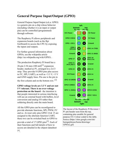
The production <strong>Raspberry</strong> Pi board has a<br />
26-pin 2.54 mm (100 mil) [1] expansion<br />
header, marked as P1, arranged in a 2x13<br />
strip. They provide 8 G<strong>PI</strong>O pins plus access<br />
to I²C, S<strong>PI</strong>, UART), as well as +3.3 V, +5 V<br />
and GND supply lines. Pin one is the pin in<br />
the first column and on the bottom row. [2]<br />
G<strong>PI</strong>O voltage levels are 3.3 V and are not<br />
5 V tolerant. There is no over-voltage<br />
protection on the board - the intention is<br />
that people interested in serious interfacing<br />
will use an external board with buffers, level<br />
conversion and analog I/O rather than<br />
soldering directly onto the main board.<br />
All the G<strong>PI</strong>O pins can be reconfigured to<br />
provide alternate functions, S<strong>PI</strong>, PWM, I²C<br />
and so. At reset only pins G<strong>PI</strong>O 14 & 15 are<br />
assigned to the alternate function UART,<br />
these two can be switched back to G<strong>PI</strong>O to<br />
provide a total of 17 G<strong>PI</strong>O pins [3] . Each of<br />
their functions and full details of how to<br />
access are detailed in the chipset datasheet<br />
[4] .<br />
The layout of the <strong>Raspberry</strong> Pi Revision 1<br />
P1 pin-header seen from the top,<br />
containing pins useable for general<br />
purpose I/O. Colour coded to the table.<br />
Source (https://sites.google.com/site/<br />
burngatehouse/home/drawings/<br />
G<strong>PI</strong>Os2.gif)