MDU Fiber Technology - Broadband Properties
MDU Fiber Technology - Broadband Properties
MDU Fiber Technology - Broadband Properties

Create successful ePaper yourself
Turn your PDF publications into a flip-book with our unique Google optimized e-Paper software.
technology for builders and developers<br />
Therefore, a key parameter of any fiber<br />
is its minimum bend radius during<br />
operation, which is the point at which<br />
it starts to lose its rated light-retention<br />
capability.<br />
One complication for designers<br />
arises because the access network is actually<br />
composed of three distinct fiber<br />
cable segments:<br />
• Feeder cables, from the central office<br />
or headend to the LCP.<br />
• Distribution cables, from that LCP<br />
to the network access point (NAP).<br />
• Drop cables, from the NAP on to the<br />
NID at each dwelling unit.<br />
Single-family-unit customers are fed with<br />
outside plant-rated fiber cables and fiber<br />
hardware, while <strong>MDU</strong> customers can be fed<br />
with a combination of OSP-rated and indoorrated<br />
fiber cable and fiber hardware.<br />
These cables can be quickly joined<br />
together with fiber optic interconnection<br />
hardware such as LCP splitter<br />
cabinets and NAP fiber terminals with<br />
ports to interconnect the drop cable to<br />
the distribution cable. These interconnections<br />
typically reduce the light level<br />
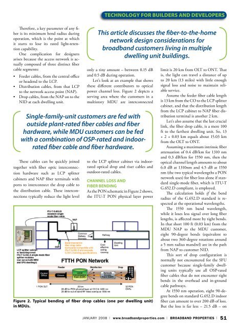
Figure 2. Typical bending of fiber drop cables (one per dwelling unit)<br />
in <strong>MDU</strong>s.<br />
This article discusses the fiber-to-the-home<br />
network design considerations for<br />
broadband customers living in multiple<br />
dwelling unit buildings.<br />
only a tiny amount – between 0.15 dB<br />
and 0.5 dB during operation.<br />
Let’s look at an example that shows<br />
these different contributors to optical<br />
power channel loss. Figure 2 depicts a<br />
serving area where the customers in a<br />
multistory <strong>MDU</strong> are interconnected<br />
to the LCP splitter cabinet via indoorrated<br />
optical drop and riser cables and<br />
outdoor-rated cables.<br />
Channel Loss and<br />
<strong>Fiber</strong> Bending<br />
As the PON schematic in Figure 2 shows,<br />
the ITU-T PON physical layer power<br />
limit is 20 km from OLT to ONT. That<br />
is, the light can travel a distance of up<br />
to 20 km (13 miles) with little enough<br />
sig nal loss and noise to maintain reliable<br />
service.<br />
Assume the feeder fiber cable length<br />
is 13 km from the CO to the LCP splitter<br />
cabinet, and that the distribution length<br />
from the LCP cabinet to NAP fiber distribution<br />
terminal is another 2 km.<br />
Let’s also assume that the last crucial<br />
link, the fiber drop cable, is a mere 100<br />
ft to the farthest dwelling unit. So, 13<br />
+ 2 + 0.03 km equals about 15.03 km<br />
from the OLT to ONT.<br />
Assuming a maximum intrinsic fiber<br />
attenuation of 0.4 dB/km for 1310 nm<br />
and 0.3 dB/km for 1550 nm, then the<br />
optical channel length amounts to about<br />
6.0 dB at 1310nm and 4.5 dB at 1550<br />
nm (the two typical wavelengths a PON<br />
network uses) for fiber loss alone if standard<br />
single-mode fiber, which is ITU-T<br />
G.652.D compliant, is employed.<br />
The calculation holds if the bend<br />
radius of the G.652.D standard is respected<br />
at the operational wavelengths.<br />
The 1550 nm band wavelength,<br />
while it loses less signal over long fiber<br />
lengths, is affected more by tight bends.<br />
In that short 100 ft (0.03 km) from the<br />
<strong>MDU</strong> NAP to the <strong>MDU</strong> customer,<br />
eight 90-degree bends (equivalent to<br />
about two 360-degree rotations around<br />
a 5 mm radius mandrel) are in the path<br />
from NAP to customer NID.<br />
This sort of drop configuration is<br />
normally not encountered for the SFU<br />
customer because single-family dwelling<br />
units typically use all OSP-rated<br />
fiber cables that do not encounter tight<br />
bends in the overhead and in-ground<br />
cable pathways.<br />
At 1550 nm operation, eight 90-degree<br />
bends on standard G.652.D indoor<br />
fiber can amount to over 200 dB of loss.<br />
But the loss is far less – 21.5 dB – on<br />
January 2008 | www.broadbandproperties.com | BROADBAND PROPERTIES | 51