Best Practices for Testing FTTH Deployments - Broadband Properties
Best Practices for Testing FTTH Deployments - Broadband Properties
Best Practices for Testing FTTH Deployments - Broadband Properties

You also want an ePaper? Increase the reach of your titles
YUMPU automatically turns print PDFs into web optimized ePapers that Google loves.
Technology<strong>Best</strong> <strong>Practices</strong> <strong>for</strong> <strong>Testing</strong><strong>FTTH</strong> <strong>Deployments</strong>Deploying fiber to the home requires learning a new set of networktesting practices. Here’s a quick summary of what operators need toknow – and when they need to know it.By Gregory Lietaert ■ JDSU CommunicationsService providers are deployingnext-generation networks deliveringhigh-bandwidth data, voiceand video services at an unprecedentedrate. Stimulus funding and the growth ofbandwidth-intensive applications suchas video streaming and peer-to-peersharing are expected to serve as the catalyst<strong>for</strong> the next leap <strong>for</strong>ward in broadbanddeployment. Running optical fibermuch deeper into the access network, insome cases all the way to the customerpremises, is an important part of thestrategy of nearly every service provider.The appeal of fiber to the home(<strong>FTTH</strong>) is that it offers the potential<strong>for</strong> practically unlimited bandwidthand also facilitates greater control overthe operation, administration and provisioningof the access system. The abilityto quickly and efficiently diagnoseproblems is critical to successful deploymentand maintenance of broadbandnetworks. This article offers a high-levelview of some practical test and measurementbest practices that help ensure successin planning, installing and troubleshooting<strong>FTTH</strong> networks.Fiber Installation <strong>Testing</strong>Fiber connectors are widely known as theweakest points in a network. The moreconnections in a network, the greateris the potential <strong>for</strong> problems caused byimproper handling during installation,operation, expansion and maintenance.Be<strong>for</strong>e mating any connectors, followthis simple inspection process to ensurethat fiber end faces are clean.PreviewStep 1: Inspect. Use a probe microscopeto inspect the fiber. If the fiberis dirty, go to Step 2. If the fiber isclean, go ahead and connect.Step 2: Clean. If the fiber is dirty, usea cleaning tool to clean the fiber endface.Step 3: Inspect. Use a probe microscopeto re-inspect and confirm thatthe fiber is clean. If the fiber is stilldirty, go back to Step 2. If the fiber isclean, go ahead and connect.In a passive optical network (PON)application – the most common <strong>FTTH</strong>flavor – the optical cable containing thefibers is laid using one of three methods:direct-burial installation, duct installationor aerial installation. Feeder cableand the distribution sections then maybe spliced in an enclosure, either to jointwo cables or to divide one large cableinto multiple smaller cables to diverge todifferent locations.Learn more at the<strong>Broadband</strong> <strong>Properties</strong>Summit about the latest tools,technologies and methods <strong>for</strong>deploying fiber to the home.After each splice, per<strong>for</strong>m opticaltime domain reflectometry (OTDR)measurements from the central office(CO) at 1310 nm and 1550 nm to verifysplice quality. Measuring from both sidesof the cable is necessary to determine theoptical loss of each fusion splice.Frame Installation andAcceptance <strong>Testing</strong>After feeder and distribution cable constructionis complete, the system is ready<strong>for</strong> frame installation. The first frame isthe fiber distribution hub (FDH), typicallyhoused in an outside cabinet thatalso contains splitters. At the FDH, allfibers coming from the CO are connectorizedor spliced to the splitters. Splitteroutputs are placed in the parking lot,with pigtails stored in a separate path toreduce fiber congestion.The second frame, the access or dropterminal, which is located close to theAbout the AuthorGregory Lietaert is responsible <strong>for</strong> product marketing in the fiber optic division ofJDSU Communications’ Test and Measurement business segment. For more in<strong>for</strong>mation,see www.jdsu.com.January 2010 | www.broadbandproperties.com | BROADBAND PROPERTIES | 69
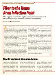
TechnologyTypical FTTx infrastructures.customer premises, consists of a spliceenclosure located either on a pole or ina manhole. Several fibers – usually four,six, eight or 12 – are extracted from thecable and spliced to be connected todrop cables.The third frame installed is usuallythe fiber distribution frame (FDF) cabinetof the optical line terminal (OLT),which is located at the CO. As in theother frames, the fiber is spliced to a pigtailto be connected to the patch panel.At the end of this process, the feederand distribution network is completeand ready <strong>for</strong> end-to-end acceptancetesting, including overall distance, insertionloss (IL) and optical return loss(ORL) tests. Be<strong>for</strong>e acceptance testingcan begin, technicians must ensure thatthe connectors and patch cords (boththose used to test and those used in thenetwork) meet network operator requirements<strong>for</strong> IL and reflectance.They may then per<strong>for</strong>m acceptancetesting with either an OTDR (1310nm/1550 nm) or a source/power meter/ORL meter (1310 nm/1550nm) combination.Each operator will have specificrequirements <strong>for</strong> loss, distance and ORLbased on the fiber cable network design.If the splitter is connectorized, testersshould per<strong>for</strong>m separate feeder anddistribution network acceptance testsusing test equipment connected at theFDF. They should measure from theFDF to the OLT and from the FDF tothe customer premises. If the splitter isspliced, testers should per<strong>for</strong>m end-toendmeasurement from the customerpremises to the OLT.In large networks, other FDFs maybe located on the feeder to distribute theAfter all the frames have been installed,acceptance testing can begin. Acceptancetests include insertion loss, optical returnloss and overall distance tests.70 | BROADBAND PROPERTIES | www.broadbandproperties.com | January 2010
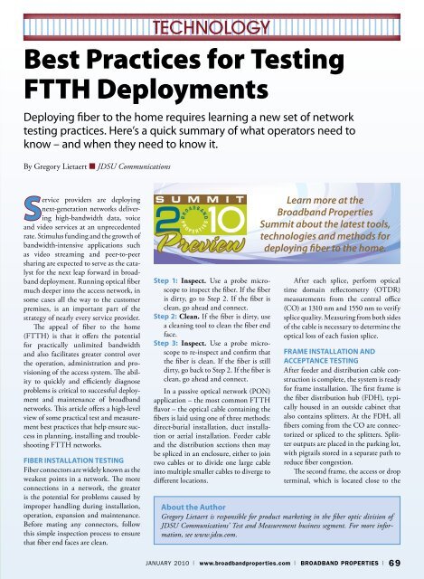
Technologydifferent cables. The same process shouldbe per<strong>for</strong>med on these frames. Testersshould then compare results to the requirementsand take corrective actionwhen needed. If the issue involves connectionsor jumpers, they should test thecorrective action with the same loss-testtools. Each result should be recorded inthe unit and also on a customer networkdatabase <strong>for</strong> maintenance purposes.The final acceptance test consistsof characterizing the complete opticalnetwork. It includes continuity checks,IL and ORL measurements of the endto-endnetwork through analysis of thetransmission optical wavelengths. Testersselect a minimum of two wavelengths(usually 1310 nm and 1550 nm) to identifyany macrobends along the network,a common fault in short-distance andhigh-fiber-count networks.With a combination source, powermeter and ORL meter, the operator canper<strong>for</strong>m automatic continuity checksand measure end-to-end IL as well asend-to-end ORL. ORL testing is particularlyimportant if the operator is usinganalog video at 1550 nm, a technologysensitive to reflectance.Turn-Up TestsAfter acceptance testing, the opticalnetwork terminals (ONTs) can be installedin the customer premises. WithPON technology, an ONT’s 1310 nmwavelength is activated only by the1490 nm signal from the OLT. There<strong>for</strong>e,to measure the output power of allwavelengths, the OLT and ONT mustbe connected. A power meter with twoports, called a selective through-modepower meter, is used to connect the fiberscoming from the OLT and the ONTat the same time so testers can per<strong>for</strong>mtests from the ONT.If the tests show that some but notall ONTs are working, the problem iseither in the distribution network or theONTs. In this case, “in-service” OTDRat 1625 nm or 1650 nm can locate thefault without disturbing the workingcustomers.On the other hand, when all ONTsare out of service, the technician shouldcheck the OLT to verify whether it istransmitting the correct power levels. IfIn turning up IP voice service, field technicians need to verify service provisioning and connectivityto signaling gateways.it is not, the OLT should be replaced. Ifthe OLT is transmitting correctly, thereis an outage in the fiber network. Testersshould per<strong>for</strong>m an OTDR measurement(1310 nm/1550 nm) from the OLTconnection toward the FDH to locate apossible break or bend in the feeder.Turning Up ServicesVideo service quality is ultimately determinedby the end user or subscriber.Video quality of experience (QoE) is asubjective concept with componentsthat are nearly impossible to measurein a practical, operational manner. Yeta service provider can make objectivemeasurements on a set of parametersthat can be used to judge the per<strong>for</strong>-mance of the network. A model <strong>for</strong>mapping objectively measurable metricsto QoE is the basis <strong>for</strong> good installationand troubleshooting procedures.Video quality of service (QoS) testingresults displayed on the field technician’stest device should show all the criticalparameters that affect video flows. If theprogram clock reference (PCR) jitteris high, <strong>for</strong> example, the decoder cannotproperly decode the video payload.Trouble with IGMP latency affects thetime it takes to change broadcast videochannels and, there<strong>for</strong>e, is an importantcomponent of customer experience.The number of lost packets in the videotransport stream, as measured by thecontinuity error indicator, is the mostExample of an OTDR trace on the JDSU T-BERD/MTS-4000 Multiple Services Test Plat<strong>for</strong>m.January 2010 | www.broadbandproperties.com | BROADBAND PROPERTIES | 71
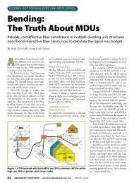
Technologycritical. Setting pass/fail thresholds intest devices <strong>for</strong> each of these parametershelps promote consistency in operationalpractices and improve service assuranceprocesses <strong>for</strong> IP video services.When turning up VoIP service, fieldtechnicians should verify service provisioningand connectivity to signalinggateways. They must also verify callquality by placing test calls both withinthe network and to the public switchedtelephone network. Critical test call parametersinclude packet delay, packetloss and jitter. However, the mean opinionscore (MOS) will be the most criticalservice-level agreement (SLA) metricused to measure overall VoIP quality.To verify Internet data services, fieldtechnicians must verify <strong>FTTH</strong> physicallayer per<strong>for</strong>mance, ISP connectivityand data service throughput. This is accomplishedusing a test tool with Webbrowser and FTP throughput test capabilities.Using selectable test file sizesand both upload and download testing,An all-in-one testing instrument saves capitaloutlay, reduces technician training time andintegrates all testing results into a single report.FTP throughput tests establish per<strong>for</strong>manceof the link that models actual usecases more closely than simple downloadtests. Per<strong>for</strong>ming an HTTP test using aWeb browser to ensure end users’ ISPaccess and connectivity is also wise.Advantages of an All-in-OneInstrumentDeploying <strong>FTTH</strong> requires techniciansto master new terminology, technologyand testing procedures to ensure thatservices are correctly provisioned andinstalled. This process can be expeditedif technicians have a single instrumentthat can per<strong>for</strong>m all required tests. Thisapproach reduces the number of instrumentsthat need to be purchased, reducestechnician training time and integratesall testing results into a single report.Systematically implementing testand measurement best practices enablestechnicians to quickly diagnose and isolate<strong>FTTH</strong> problems impacting QoSand QoE <strong>for</strong> fast correction. A broadline of test equipment makes it possibleto arm technicians and engineers withan optimized tool set that will enablethem to quickly and efficiently diagnoseproblems at an af<strong>for</strong>dable cost. BBP<strong>Broadband</strong> <strong>Properties</strong>MagazineCongratulatesFor becoming a Silver Sponsor at the2010 <strong>Broadband</strong> <strong>Properties</strong> Summit.For more in<strong>for</strong>mation on Dish Network, visit www.dishnetwork.com/commercial.You are cordially invited to come see Dish Network at the upcomingApril 26 – 28, 2010InterContinental Hotel – DallasAddison, TexasThe Leading Conference on <strong>Broadband</strong> Technologies and ServicesTo Exhibit or Sponsor, contact: Irene Prescott at irene@broadbandproperties.com, or call 316-733-9122.For other inquiries, call 877-588-1649, or visit www.bbpmag.com.72 | BROADBAND PROPERTIES | www.broadbandproperties.com | January 2010