MDU Fiber Technology - Broadband Properties
MDU Fiber Technology - Broadband Properties
MDU Fiber Technology - Broadband Properties

You also want an ePaper? Increase the reach of your titles
YUMPU automatically turns print PDFs into web optimized ePapers that Google loves.
technology for builders and developers<br />
Bending:<br />
The Truth About <strong>MDU</strong>s<br />
Reliable, cost-effective fiber installations in multiple dwelling unit structures<br />
need bend-insensitive fiber. Here’s how to calculate the signal-loss budget.<br />
By Mark Turner ■ Corning Cable Systems<br />
Are broadband requirements really<br />
any different for a customer in a<br />
1200-square-foot condominium<br />
than for one in the 2500-square-foot<br />
house just across the street<br />
It’s hard to answer “yes” knowing<br />
that broadband customers, regardless<br />
of where they live, want the same compelling<br />
TV channel lineup, ultra-highspeed<br />
connection to and from the Internet,<br />
and reliable phone service.<br />
Physically, though, it is clear that<br />
fiber bending is an issue where fiber<br />
drop cables are placed indoors, so from<br />
that perspective a “yes” answer is the<br />
right one. The simple truth is that fiber<br />
bending matters if you want to reach<br />
those <strong>MDU</strong> customers without incurring<br />
excessive construction costs. This<br />
article discusses the fiber-to-the-home<br />
(FTTH) network design considerations<br />
for broadband customers living in multiple<br />
dwelling unit buildings (<strong>MDU</strong>s).<br />
<strong>MDU</strong>s Versus SFUs<br />
The key difference between <strong>MDU</strong> and<br />
single-family unit (SFU) networks is in<br />
the FTTH physical layer. SFU customers<br />
are fed with outside plant (OSP)-<br />
rated fiber cables and fiber hardware,<br />
while <strong>MDU</strong> customers can be fed with<br />
a combination of OSP-rated and indoorrated<br />
fiber cable and fiber hardware.<br />
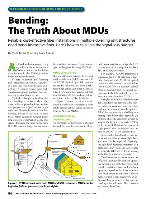
Figure 1 shows a typical scenario<br />
where a single local convergence point<br />
(LCP) splitter cabinet serves customers<br />
living in SFUs or <strong>MDU</strong>s.<br />
Figure 1. FTTH network with both <strong>MDU</strong> and SFU customers. <strong>MDU</strong>s can be<br />
high-rise (left) or garden-style (lower right).<br />
Contributors to<br />
Channel Loss<br />
An important consideration is channel<br />
loss and the need for the amount of optical<br />
power available to design the LCP<br />
serving area to be transparent for both<br />
SFU and <strong>MDU</strong> customers.<br />
For example, GPON transmission<br />
equipment for FTTH networks is typically<br />
designed with 28 dB of optical<br />
power available between the optical line<br />
terminal (OLT) in the operator’s central<br />
office or headend and the optical network<br />
terminals (ONTs) inside each customer’s<br />
network interface (NID).<br />
A single GPON OLT reliably delivers<br />
2.4 Gbps down the network to the splitters<br />
near the customers and 1.2 Gbps<br />
back up the network from the splitters.<br />
All of the customers in a dwelling unit<br />
sharing that bandwidth (typically 32<br />
of them) share the reliability as well, as<br />
long as the light level at each ONT is<br />
no less than 28 dB below the amount of<br />
“light power” that was injected into the<br />
fiber by the OLT at the central office.<br />
Also, if other broadband services are<br />
provided out-of-band, those light budgets<br />
must also be respected. Physically,<br />
the light level decreases uniformly as it<br />
propagates away from the laser source<br />
(at either the OLT or ONT end) as long<br />
as the fiber is not bent excessively.<br />
The fiber structure, also known as the<br />
refractive-index profile, and the operating<br />
wavelength(s) of the laser source and<br />
launch conditions (how well the laser<br />
signal is coupled to the fiber) influence<br />
how much power is lost when a fiber is<br />
bent. If a fiber is bent excessively, an additional<br />
drop in power at that specific<br />
bending point will occur. This is known<br />
as a “macro-bend” loss.<br />
50 | BROADBAND PROPERTIES | www.broadbandproperties.com | January 2008
technology for builders and developers<br />
Therefore, a key parameter of any fiber<br />
is its minimum bend radius during<br />
operation, which is the point at which<br />
it starts to lose its rated light-retention<br />
capability.<br />
One complication for designers<br />
arises because the access network is actually<br />
composed of three distinct fiber<br />
cable segments:<br />
• Feeder cables, from the central office<br />
or headend to the LCP.<br />
• Distribution cables, from that LCP<br />
to the network access point (NAP).<br />
• Drop cables, from the NAP on to the<br />
NID at each dwelling unit.<br />
Single-family-unit customers are fed with<br />
outside plant-rated fiber cables and fiber<br />
hardware, while <strong>MDU</strong> customers can be fed<br />
with a combination of OSP-rated and indoorrated<br />
fiber cable and fiber hardware.<br />
These cables can be quickly joined<br />
together with fiber optic interconnection<br />
hardware such as LCP splitter<br />
cabinets and NAP fiber terminals with<br />
ports to interconnect the drop cable to<br />
the distribution cable. These interconnections<br />
typically reduce the light level<br />
Figure 2. Typical bending of fiber drop cables (one per dwelling unit)<br />
in <strong>MDU</strong>s.<br />
This article discusses the fiber-to-the-home<br />
network design considerations for<br />
broadband customers living in multiple<br />
dwelling unit buildings.<br />
only a tiny amount – between 0.15 dB<br />
and 0.5 dB during operation.<br />
Let’s look at an example that shows<br />
these different contributors to optical<br />
power channel loss. Figure 2 depicts a<br />
serving area where the customers in a<br />
multistory <strong>MDU</strong> are interconnected<br />
to the LCP splitter cabinet via indoorrated<br />
optical drop and riser cables and<br />
outdoor-rated cables.<br />
Channel Loss and<br />
<strong>Fiber</strong> Bending<br />
As the PON schematic in Figure 2 shows,<br />
the ITU-T PON physical layer power<br />
limit is 20 km from OLT to ONT. That<br />
is, the light can travel a distance of up<br />
to 20 km (13 miles) with little enough<br />
sig nal loss and noise to maintain reliable<br />
service.<br />
Assume the feeder fiber cable length<br />
is 13 km from the CO to the LCP splitter<br />
cabinet, and that the distribution length<br />
from the LCP cabinet to NAP fiber distribution<br />
terminal is another 2 km.<br />
Let’s also assume that the last crucial<br />
link, the fiber drop cable, is a mere 100<br />
ft to the farthest dwelling unit. So, 13<br />
+ 2 + 0.03 km equals about 15.03 km<br />
from the OLT to ONT.<br />
Assuming a maximum intrinsic fiber<br />
attenuation of 0.4 dB/km for 1310 nm<br />
and 0.3 dB/km for 1550 nm, then the<br />
optical channel length amounts to about<br />
6.0 dB at 1310nm and 4.5 dB at 1550<br />
nm (the two typical wavelengths a PON<br />
network uses) for fiber loss alone if standard<br />
single-mode fiber, which is ITU-T<br />
G.652.D compliant, is employed.<br />
The calculation holds if the bend<br />
radius of the G.652.D standard is respected<br />
at the operational wavelengths.<br />
The 1550 nm band wavelength,<br />
while it loses less signal over long fiber<br />
lengths, is affected more by tight bends.<br />
In that short 100 ft (0.03 km) from the<br />
<strong>MDU</strong> NAP to the <strong>MDU</strong> customer,<br />
eight 90-degree bends (equivalent to<br />
about two 360-degree rotations around<br />
a 5 mm radius mandrel) are in the path<br />
from NAP to customer NID.<br />
This sort of drop configuration is<br />
normally not encountered for the SFU<br />
customer because single-family dwelling<br />
units typically use all OSP-rated<br />
fiber cables that do not encounter tight<br />
bends in the overhead and in-ground<br />
cable pathways.<br />
At 1550 nm operation, eight 90-degree<br />
bends on standard G.652.D indoor<br />
fiber can amount to over 200 dB of loss.<br />
But the loss is far less – 21.5 dB – on<br />
January 2008 | www.broadbandproperties.com | BROADBAND PROPERTIES | 51
technology for builders and developers<br />
A key parameter of any fiber is its minimum<br />
bend radius during operation, which is the<br />
point at which it starts to lose its rated<br />
light-retention capability.<br />
G.657.A bend-improved fiber. And it is<br />
only 4 dB on bend-tolerant G.657.B fiber.<br />
The new bend-insensitive fiber technologies<br />
suffer a loss of only 0.2 dB.<br />
Additionally, between the OLT and<br />
ONTs there are<br />
other sources of<br />
insertion loss. The<br />
splitter module<br />
can attenuate the<br />
signal by as much<br />
as 17.5 dB on<br />
any given output<br />
lead and the six<br />
fiber optic connections<br />
in the<br />
channel also drop<br />
the optical power. Currently, the typical<br />
insertion loss for a field connection<br />
is 0.15 dB, and a fusion splice is about<br />
0.1 dB. However, a mode-field diameter<br />
mismatch could also cause more loss if<br />
the extreme-bend drop fiber is not fully<br />
backward-compatible with industrystandard<br />
G.652.D single-mode fiber.<br />
It is essential then to use a fiber that<br />
is known to be fully backward-compatible<br />
with G.652.D to minimize coupling<br />
loss from fiber to fiber. Therefore, the<br />
splitter, connections and fusion splices<br />
typically add another 17.8 dB of channel<br />
insertion loss. The calculation is:<br />
16.5 + (0.15 * 6) + (0.1 * 4)<br />
And the WDM combiner (to mix<br />
the PON and RF video signals onto a<br />
single fiber) in the central office or headend<br />
can attenuate the power as much as<br />
3 dB.<br />
Bend-insensitive single-mode fiber is the only<br />
fiber that enables an FTTH designer to ignore<br />
costly cable pathway creation and simply<br />
design the <strong>MDU</strong> portion of the PON the same<br />
way as the SFU portion.<br />
Assuming the link loss budget for RF<br />
video overlay operating in the 1550 nm<br />
band is 25 dB, the only fiber that will<br />
operate in the typical <strong>MDU</strong> configuration<br />
requiring many 90-degree bends is<br />
bend-insensitive.<br />
Stated another way, bend-insensitive<br />
single-mode fiber is the only fiber that<br />
enables an FTTH designer to ignore<br />
costly cable pathway creation and simply<br />
design the <strong>MDU</strong> portion of the PON<br />
the same way as the SFU portion.<br />
Table 1 summarizes this information<br />
from the configuration shown in Figure<br />
2. Note that maximum cabled fiber loss<br />
(intrinsic) is calculated to build in some<br />
headroom with respect to the link loss<br />
budget of 25 dB.<br />
Summary<br />
An FTTH designer is now free to design<br />
<strong>MDU</strong>s just like SFUs because bend-insensitive<br />
fiber enables the optical power to<br />
pass through many tight bends down to<br />
a 5 mm radius (such as 90-degree bends<br />
around wall corners and at the wall-ceiling<br />
transition) with very low loss.<br />
This is extremely important because<br />
without this new fiber technology, very<br />
costly cable pathways<br />
would otherwise<br />
be needed<br />
in order to get<br />
enough optical<br />
power to the<br />
<strong>MDU</strong> customer’s<br />
ONT.<br />
Also, its backwards<br />
compatibility<br />
with industry<br />
standard ITU-T<br />
G.652.D single-mode fiber assures that<br />
mode-field diameter mismatch does not<br />
cause additional loss at fiber interconnections<br />
and splices. BBP<br />
About the Author<br />
Mark Turner is Market Development<br />
Manager at Corning Cable Systems.<br />
Save the Dates<br />
April 28 - 30<br />
Single-mode<br />
fiber type<br />
G.652.D<br />
G.657.A<br />
G.657.B<br />
Bendinsensitive<br />
(G.652.A and<br />
.B capable)<br />
Typical WDM<br />
combiner<br />
(dB)<br />
n/a<br />
2.5<br />
n/a<br />
n/a<br />
OSP feeder<br />
(dB)<br />
3.9<br />
not required<br />
not required<br />
not required<br />
OSP<br />
distribution<br />
(dB)<br />
0.6<br />
not required<br />
not required<br />
not required<br />
Indoor <strong>MDU</strong><br />
drop (dB) – 8<br />
90° bends<br />
Table 1. RF video overlay channel loss (1550 nm) from OLT to <strong>MDU</strong> ONT, in the installation shown in Figure 2.<br />
200<br />
21.5<br />
4<br />
0.2<br />
Typical<br />
splitter lead<br />
loss (dB)<br />
bend-limited<br />
16.5<br />
not needed<br />
not used<br />
currently<br />
<strong>Fiber</strong> joining<br />
point loss<br />
1.3<br />
1.3<br />
≥ 1.3<br />
1.3<br />
OLT to ONT<br />
channel loss<br />
(dB)<br />
224.8<br />
46.3<br />
≥ 28.8<br />
25.0<br />
52 | BROADBAND PROPERTIES | www.broadbandproperties.com | January 2008