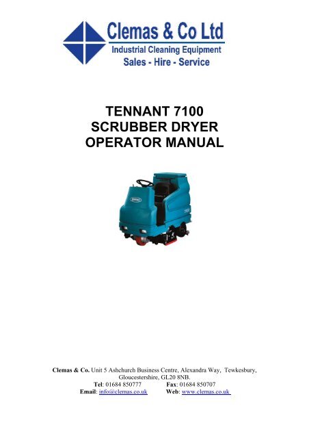
TENNANT 7100 SCRUBBER DRYER OPERATOR MANUAL - Clemas
TENNANT 7100 SCRUBBER DRYER OPERATOR MANUAL - Clemas
TENNANT 7100 SCRUBBER DRYER OPERATOR MANUAL - Clemas

Create successful ePaper yourself
Turn your PDF publications into a flip-book with our unique Google optimized e-Paper software.
<strong>TENNANT</strong> <strong>7100</strong><br />
<strong>SCRUBBER</strong> <strong>DRYER</strong><br />
<strong>OPERATOR</strong> <strong>MANUAL</strong><br />
<strong>Clemas</strong> & Co. Unit 5 Ashchurch Business Centre, Alexandra Way, Tewkesbury,<br />
Gloucestershire, GL20 8NB.<br />
Tel: 01684 850777 Fax: 01684 850707<br />
Email: info@clemas.co.uk Web: www.clemas.co.uk
SAFETY PRECAUTIONS<br />
SAFETY PRECAUTIONS<br />
The following symbols are used throughout this<br />
manual as indicated in their description:<br />
WARNING: To warn of hazards or unsafe<br />
practices that could result in severe<br />
personal injury or death.<br />
FOR SAFETY: To identify actions that<br />
must be followed for safe operation of<br />
equipment.<br />
This machine is designed solely for scrubbing dirt<br />
and dust in an indoor environment. Tennant does<br />
not recommend using this machine in any other<br />
environment.<br />
The following information signals potentially<br />
dangerous conditions to the operator or<br />
equipment. Read this manual carefully. Know<br />
when these conditions can exist. Locate all safety<br />
devices on the machine. Then, take necessary<br />
steps to train machine operating personnel.<br />
Report machine damage or faulty operation<br />
immediately. Do not use the machine if it is not in<br />
proper operating condition.<br />
WARNING: Batteries emit hydrogen gas.<br />
Explosion or fire can result. Keep<br />
sparks and open flame away. Keep<br />
covers open when charging.<br />
WARNING: Flammable materials can<br />
cause an explosion or fire. Do not use<br />
flammable materials in tank(s).<br />
WARNING: Flammable materials or<br />
reactive metals can cause explosion or<br />
fire. Do not pick up.<br />
FOR SAFETY:<br />
1. Do not operate machine:<br />
- Unless trained and authorized.<br />
- Unless operation manual is read and<br />
understood.<br />
- In flammable or explosive areas unless<br />
designed for use in those areas.<br />
2. Before starting machine:<br />
- Make sure all safety devices are in<br />
place and operate properly.<br />
- Check brakes and steering for proper<br />
operation (if so equipped).<br />
3. When using machine:<br />
- Go slow on inclines and slippery<br />
surfaces.<br />
- Use care when backing machine.<br />
- Follow mixing and handling<br />
instructions on chemical containers.<br />
4. Before leaving or servicing machine:<br />
- Stop on level surface.<br />
- Set parking brake.<br />
- Turn off machine and remove key.<br />
5. When servicing machine:<br />
- Avoid moving parts. Do not wear loose<br />
jackets, shirts, or sleeves when<br />
working on machine.<br />
- Block machine tires before jacking<br />
machine up.<br />
- Jack machine up at designated<br />
locations only. Block machine up with<br />
jack stands.<br />
- Use hoist or jack that will support the<br />
weight of the machine.<br />
- Wear eye and ear protection when<br />
using pressurized air or water.<br />
- Disconnect battery connections before<br />
working on machine.<br />
- Avoid contact with battery acid.<br />
- Use Tennant supplied or equivalent<br />
replacement parts.<br />
6. When loading/unloading machine<br />
onto/off truck or trailer:<br />
- Turn off machine.<br />
- Use truck or trailer that will support<br />
the weight of the machine.<br />
- Use winch. Do not drive the machine<br />
onto/off the truck or trailer unless the<br />
load height is 380 mm (15 in) or less<br />
from the ground.<br />
- Set parking brake after machine is<br />
loaded.<br />
- Block machine tires.<br />
- Tie machine down to truck or trailer.<br />
<strong>7100</strong> 330699 (6 -02)<br />
3
SAFETY PRECAUTIONS<br />
The safety labels appear on the machine in the<br />
locations indicated. If these or any label becomes<br />
damaged or illegible, install a new label in its<br />
place.<br />
BATTERY CHARGING LABEL - LOCATED ON<br />
AND UNDERNEATH THE SEAT SUPPORT.<br />
FLAMMABLE MATERIALS LABEL - LOCATED<br />
ON THE UNDERSIDE OF THE TANK COVER<br />
AND ON THE LEFT SIDE OF THE <strong>OPERATOR</strong><br />
COMPARTMENT.<br />
FLAMMABLE SPILLS LABEL -<br />
LOCATED ON THE SEAT SUPPORT.<br />
FOR SAFETY LABEL - LOCATED ON THE<br />
SEAT SUPPORT.<br />
353450<br />
4<br />
<strong>7100</strong> 330699 (12 -00)
OPERATION<br />
OPERATION<br />
<strong>OPERATOR</strong> RESPONSIBILITY<br />
- The operator’s responsibility is to take care<br />
of the daily maintenance and checkups of<br />
the machine to keep it in good working<br />
condition. The operator must inform the<br />
service mechanic or supervisor when the<br />
maintenance intervals are required as stated<br />
in the MAINTENANCE section of this<br />
manual.<br />
- Read this manual carefully before operating<br />
this machine.<br />
FOR SAFETY: Do not operate machine,<br />
unless operation manual is read and<br />
understood.<br />
- Check the machine for shipping damage.<br />
Check to make sure machine is complete<br />
per shipping instructions.<br />
- Keep your machine regularly maintained by<br />
following the maintenance information in this<br />
manual. We recommend taking advantage of<br />
a regularly scheduled service contract from<br />
your <strong>TENNANT</strong> representative.<br />
07324<br />
- Order parts and supplies directly from your<br />
authorized <strong>TENNANT</strong> representative. Use<br />
the parts manual provided when ordering<br />
parts.<br />
<strong>7100</strong> 330699 (12 -00)<br />
5
OPERATION<br />
MACHINE COMPONENTS<br />
M<br />
L<br />
A<br />
B<br />
K<br />
C<br />
D<br />
E<br />
J<br />
F<br />
N<br />
I<br />
H<br />
G<br />
A. Vacuum fan inlet screen<br />
B. Tank Cover<br />
C. Solution tank<br />
D. Operator’s seat<br />
E. Batteries<br />
F. Rear squeegee<br />
G. Side squeegee<br />
H. Scrub head<br />
I. Front wheel<br />
J. Operating lights<br />
K. Steering wheel<br />
L. Recovery tank<br />
M. FaSTt PAK (option)<br />
N. FaSTt solution system (option)<br />
6<br />
<strong>7100</strong> 330699 (3 -04)
OPERATION<br />
CONTROL PANEL SYMBOLS<br />
These symbols identify controls and displays on<br />
the machine:<br />
Key switch Circuit breaker #1<br />
Battery charge Circuit breaker #2<br />
Scrub Circuit breaker #3<br />
Squeegee Circuit breaker #4<br />
Brush pressure Circuit breaker #5<br />
ESt (Option) Circuit breaker #6<br />
FaSTt (Option) Circuit breaker #7<br />
Solution tank low Circuit breaker #8<br />
Recovery tank full Circuit breaker #9<br />
Solution flow<br />
Power wand switch (option)<br />
Operating lights switch<br />
<strong>7100</strong> 330699 (3 -04)<br />
7
OPERATION<br />
CONTROLS AND INSTRUMENTS<br />
A<br />
B<br />
C<br />
D<br />
E<br />
F G H<br />
I<br />
J<br />
K<br />
S<br />
R<br />
Q<br />
P<br />
O<br />
N<br />
M<br />
L<br />
A. Steering wheel<br />
B. Control panel<br />
C. Battery discharge indicator<br />
D. Recovery tank full indicator<br />
E. Solution tank empty indicator<br />
F. Operating lights switch<br />
G. Power wand switch (option)<br />
H. Power kill switch<br />
I. Horn button<br />
J. Solution flow lever<br />
K. On/Off key switch<br />
L. Directional pedal<br />
M. Brake pedal<br />
N. Hourmeter<br />
O. Parking brake pedal<br />
P. ESt switch (option)<br />
or FaSTt switch (option)<br />
Q. Circuit breaker panel<br />
R. Rear squeegee switch<br />
S. Scrub switch<br />
8<br />
<strong>7100</strong> 330699 (3 -04)
OPERATION<br />
OPERATION OF CONTROLS<br />
BRAKE PEDAL<br />
The brake pedal stops the machine.<br />
Stop: Take your foot off the directional pedal and<br />
allow it return to the Neutral position. Step on the<br />
brake pedal.<br />
PARKING BRAKE PEDAL<br />
The parking brake pedal sets the front wheel<br />
brake.<br />
Set: Press the brake pedal down as far as<br />
possible, then press on the parking brake pedal<br />
with the toe of your foot to lock the parking brake<br />
pedal in place.<br />
FOR SAFETY: Before leaving or<br />
servicing machine, stop on level<br />
surface, set parking brake, turn off<br />
machine, and remove key.<br />
Release: Press down on the brake pedal until the<br />
parking brake releases.<br />
DIRECTIONAL PEDAL<br />
The directional pedal controls direction of travel<br />
and the propelling speed of the machine. You<br />
change the speed of the machine with the<br />
pressure of your foot; the harder you press the<br />
faster the machine travels.<br />
When the machine is moving forward and the<br />
directional pedal is reversed, the machine will<br />
coast for a short distance before changing<br />
direction. Use the brake pedal to stop the<br />
machine.<br />
<strong>7100</strong> 330699 (12 -00)<br />
9
OPERATION<br />
Forward: Press the top of the directional pedal<br />
with the upper part of your foot.<br />
NOTE: The machine will not travel unless the<br />
operator is sitting in the operator’s seat.<br />
Reverse: Press the bottom of the directional<br />
pedal with the heel of your foot.<br />
When the directional pedal is placed into the<br />
reverse position, the rear squeegee will<br />
automatically raise. After a short delay, the<br />
vacuum will stop.<br />
Neutral: Take your foot off the directional pedal<br />
and it will return to the neutral position.<br />
When the directional pedal returns to the neutral<br />
position, the scrub brushes will stop and after a<br />
short delay, the scrub head will raise.<br />
STEERING WHEEL<br />
The steering wheel controls the machine’s<br />
direction of travel.<br />
Left: Turn the steering wheel to the left.<br />
Right: Turn the steering wheel to the right.<br />
10<br />
<strong>7100</strong> 330699 (12 -00)
OPERATION<br />
ON-OFF KEY SWITCH<br />
The on-off key switch controls machine power with<br />
akey.<br />
FOR SAFETY: When starting machine,<br />
keep foot on brake and directional pedal<br />
in neutral.<br />
On: Turn the key all the way clockwise and<br />
release it to the on position.<br />
Off: Turn the key all the way counterclockwise<br />
until it clicks into the off position.<br />
POWER KILL SWITCH<br />
The power kill switch halts all power to the<br />
machine.<br />
Stop machine power: Press the power kill switch.<br />
Restart: Turn off the machine with the on/off<br />
switch. Turn the power kill switch to the right to<br />
release the switch. Turn on the machine with the<br />
on/off key switch.<br />
HOURMETER<br />
The hourmeter records the number of hours the<br />
machine has been operated. Check the hourmeter<br />
regularly; this information is used to determine<br />
when to perform routine machine maintenance.<br />
<strong>7100</strong> 330699 (12 -00)<br />
11
OPERATION<br />
OPERATING LIGHTS SWITCH<br />
The operating lights switch powers the headlights<br />
and the hazard lights (option) on and off.<br />
On: Press the top of the operating lights switch.<br />
Off: Press the bottom of the operating lights<br />
switch.<br />
POWER WAND SWITCH (OPTION)<br />
The power wand switch (option) powers the power<br />
wand on and off.<br />
On: Press the top of the power wand switch.<br />
Off: Press the bottom of the power wand switch.<br />
HORN BUTTON<br />
The horn button operates the horn.<br />
Sound: Press the horn button.<br />
12<br />
<strong>7100</strong> 330699 (12 -00)
OPERATION<br />
SCRUB SWITCH<br />
The scrub switch controls the scrub head, scrub<br />
brushes, squeegee, and vacuum fan. The scrub<br />
switch is also used to set the scrub brush<br />
pressure.<br />
Start scrubbing: Press the scrub switch. The<br />
indicator light will illuminate, the squeegee will<br />
lower, and the vacuum fan will start. The<br />
scrubbing system and solution flow will start when<br />
the directional pedal is pressed and the machine<br />
begins to move forward.<br />
Stop scrubbing: Press the scrub switch. The<br />
pressure indicator light will go out. The scrub<br />
brushes will stop, the scrub head will raise, and<br />
the solution flow will stop. After a short delay, the<br />
rear squeegee will automatically raise. After<br />
another delay, the vacuum will stop.<br />
The brush down pressure indicators display the<br />
pressure selection. The brush pressure indicator<br />
has three positions. Brush pressure increases as<br />
the indicator light moves to the right across the<br />
display. Travel speed and floor conditions will<br />
affect the scrubbing performance. Under normal<br />
conditions, the brush pressure should be set in<br />
one of the minimum settings. Set the brush<br />
pressure in one of the maximum settings to scrub<br />
a heavily soiled floor.<br />
Change brush pressure: Press and hold the scrub<br />
switch. The pressure indicator light will cycle<br />
through the three brush pressure settings. When<br />
the switch is pressed and held, the brush pressure<br />
will increase until it reaches the maximum setting.<br />
The pressure will then return to the minimum<br />
setting. Release the scrub switch when the<br />
desired setting is indicated on the display.<br />
NOTE: When the machine power is turned off, the<br />
brush pressure will remain in the last setting used.<br />
<strong>7100</strong> 330699 (12 -00)<br />
13
OPERATION<br />
REAR SQUEEGEE SWITCH<br />
The rear squeegee switch controls the vacuum<br />
fan and the position of the rear squeegee. The<br />
rear squeegee can be operated separately from<br />
the scrub brushes for the purpose of picking-up<br />
excess water without scrubbing, or double<br />
scrubbing without water pick up<br />
Lower squeegee and start the vacuum fan: Press<br />
the rear squeegee switch. The indicator light<br />
above the switch will illuminate.<br />
Raise squeegee and stop the vacuum fan: Press<br />
the squeegee switch. The indicator light above the<br />
switch will go off. There will be a slight delay<br />
before the vacuum shuts off.<br />
NOTE: The rear squeegee lowers and the<br />
scrubbing vacuum starts automatically, when the<br />
scrubbing operations start.<br />
NOTE: The rear squeegee will raise and the<br />
scrubbing vacuum will shut off after a short delay<br />
when the machine travels in reverse.<br />
NOTE: The rear squeegee will raise and the<br />
scrubbing vacuum fan will shut off after a short<br />
delay when the scrubbing operations are shut off.<br />
ESt SWITCH (OPTION)<br />
The ESt (Extended Scrub) switch turns on and<br />
off the solution recycling system. When the<br />
scrubbing functions have started, the ESt will<br />
default to the last setting used.<br />
On: Press the ESt switch. The indicator light<br />
above the switch will illuminate.<br />
Off: Press the ESt switch. The indicator light<br />
above the switch will turn off.<br />
NOTE: The solution tank empty indicator light<br />
will not illuminate with machines equipped with<br />
the ESt option.<br />
14<br />
<strong>7100</strong> 330699 (12 -01)
OPERATION<br />
FaSTt SWITCH (OPTION)<br />
The FaSTt switch (option) enables the FaSTt<br />
(Foam Scrubbing Technology) system. When the<br />
FaSTt system is enabled, it is turned on and off<br />
with the scrub switch.<br />
On: Press the FaSTt switch. The indicator light<br />
above the switch will illuminate.<br />
Off: Press the FaSTt switch. The indicator light<br />
above the switch will turn off.<br />
NOTE: The FaST system will not start until the<br />
directional pedal is pressed.<br />
NOTE: To use the machine for conventional<br />
scrubbing, disable the FaSTt system by turning<br />
the FaSTt switch off.<br />
NOTE: Do not enable the FaSTt system with<br />
conventional cleaning detergents in the solution<br />
tank. Drain, raise and refill the solution tank with<br />
clear cool water only before operating the FaSTt<br />
system. Conventional cleaning detergents/<br />
restorers may cause failure to the FaSTt solution<br />
system.<br />
SOLUTION TANK EMPTY INDICATOR<br />
The solution tank empty indicator will illuminate<br />
when the solution tank is empty.<br />
NOTE: Machines with the ESt option do not have<br />
this feature.<br />
RECOVERY TANK FULL INDICATOR<br />
The recovery tank full indicator will illuminate<br />
when the recovery tank is full.<br />
NOTE: When the indicator illuminates, all<br />
scrubbing functions will shut off automatically.<br />
<strong>7100</strong> 330699 (3 -04)<br />
15
OPERATION<br />
BATTERY DISCHARGE INDICATOR<br />
The battery discharge indicator displays the<br />
charge level of the batteries while the machine is<br />
operating.<br />
When the batteries are fully charged, all four<br />
indicator lights are lit. As the batteries discharge,<br />
the indicator lights will go out from right to left. The<br />
batteries should be recharged when the indicator<br />
on the left flashes. When the indicator flashes, all<br />
scrubbing functions will shut off automatically.<br />
Drive the machine to the battery charging area<br />
and charge the batteries immediately after the<br />
battery discharge indicator begins to flash.<br />
NOTE: The battery discharge indicator will not<br />
stop flashing until the batteries have been fully<br />
charged.<br />
NOTE: Do not charge the batteries more often<br />
than is necessary to prolong the life of the<br />
batteries. Do not charge the batteries with a “top<br />
off” charge if there is enough remaining charge in<br />
the batteries for the next machine use. Discharge<br />
the batteries to a 20% level, when the battery<br />
discharge indicator segments shut off, before fully<br />
charging the batteries. Do not allow the batteries<br />
to become completely discharged as this will also<br />
damage the batteries. See BATTERIES in the<br />
MAINTENANCE section.<br />
16<br />
<strong>7100</strong> 330699 (12 -00)
OPERATION<br />
CIRCUIT BREAKERS<br />
Circuit breakers are resetable electrical circuit<br />
protection devices designed to stop the flow of<br />
current in the event of a circuit overload. Once a<br />
circuit breaker is tripped, reset it manually by<br />
pressing the reset button after the breaker has<br />
cooled down.<br />
If the overload that caused the circuit breaker to<br />
trip is still present, the circuit breaker will continue<br />
to stop current flow until the problem is corrected.<br />
The circuit breakers are located on the operator<br />
console.<br />
Circuit<br />
Breaker Rating Circuit Protected<br />
CB1 5A Machine power<br />
CB2 10 A Lights<br />
CB3 10 A Horn<br />
CB4 10 A Power wand/<br />
Back up alarm<br />
CB5 10 A Control panel<br />
CB6 20 A Vacuum Fan (single)<br />
CB6 40 A Vacuum Fan (dual)<br />
CB7 10 A ESt System (option)<br />
FaSTt System (option)<br />
CB8 25 A Left brush motor<br />
CB9 25 A Right brush motor<br />
The chart below shows the circuit breakers and<br />
the electrical components they protect.<br />
FUSE<br />
The fuse is a one-time protection device designed<br />
to stop the flow of current in the event of a circuit<br />
overload.<br />
NOTE: Always replace the fuse with a fuse of the<br />
same amperage.<br />
The fuse is located behind the operator console.<br />
Access the fuse by lowering the operator console.<br />
Fuse Rating Circuit Protected<br />
FU-1 40 A Propelling<br />
<strong>7100</strong> 330699 (3 -04)<br />
17
OPERATION<br />
SOLUTION FLOW LEVER<br />
The solution flow lever controls the amount of<br />
solution that flows to the floor while scrubbing.<br />
Increase solution flow: Push the lever forward.<br />
Decrease solution flow: Pull the lever backward.<br />
NOTE: The machine is equipped with a solenoid<br />
valve that automatically stops the solution flow<br />
when the directional pedal is in the neutral position<br />
or when the scrub head is raised.<br />
NOTE: When using the FaSTt system (option),<br />
the solution flow lever is nonfunctional. The<br />
FaSTt system flow rate is pre -set.<br />
<strong>OPERATOR</strong> SEAT<br />
The operator seat is a fixed back style with a<br />
forward--backward adjustment.<br />
Adjust: Pull the lever outward and slide the seat<br />
to the desired position, then release the lever.<br />
NOTE: The machine will not travel unless the<br />
operator is sitting in the operator’s seat.<br />
SEAT SUPPORT ARM<br />
The seat support arm holds the seat up to allow<br />
access to the batteries. The seat support arm<br />
automatically engages when the seat is lifted all<br />
the way up. Lower the seat support by slightly<br />
raising it while pushing the support arm inward.<br />
18<br />
<strong>7100</strong> 330699 (3 -04)
OPERATION<br />
SQUEEGEE WHEEL CAMS<br />
The squeegee wheel cams adjust the rear<br />
squeegee deflection along the entire length of the<br />
rear squeegee. There are wheel cams at either<br />
end of the squeegee.<br />
Increase deflection: Turn the cams<br />
counterclockwise.<br />
Decrease deflection: Turn the cams clockwise.<br />
SQUEEGEE LEVELING KNOB<br />
The squeegee leveling knob adjusts the deflection<br />
at the ends of the rear squeegee.<br />
The squeegee leveling knob is located directly<br />
behind the squeegee suction hose. DO NOT<br />
disconnect the suction hose from the squeegee<br />
frame when leveling the squeegee.<br />
Increase end deflection: Turn the squeegee<br />
leveling knob counterclockwise to increase the<br />
deflection at the end of the squeegees.<br />
Decrease end deflection: Turn the squeegee<br />
leveling knob clockwise to decrease the deflection<br />
at the end of the squeegees.<br />
<strong>7100</strong> 330699 (12 -00)<br />
19
OPERATION<br />
HOW THE MACHINE WORKS<br />
The following machine components work together<br />
to effectively clean dirty floors: solution tank, scrub<br />
brushes, squeegee, vacuum fan, and recovery<br />
tank.<br />
Water and detergent from the solution tank flow to<br />
the floor through a solution valve. The brushes<br />
use the detergent and water solution to scrub the<br />
floor clean. As the machine propels forward, the<br />
squeegee wipes the dirty solution from the floor.<br />
The suction created by the vacuum fan then<br />
draws the dirty solution from the squeegee into<br />
the recovery tank.<br />
The steering wheel controls the direction of<br />
machine travel.The directional pedal controls the<br />
speed and direction of the machine. The brake<br />
pedal slows and stops the machine.<br />
When using the ESt mode (option), the dirty<br />
solution in the recovery tank is filtered and<br />
returned to the solution tank to be reused for<br />
extended scrubbing.<br />
The four available scrub head types use disk or<br />
cylindrical brushes.<br />
Two different widths of scrub heads are available<br />
for each type. Both the cylindrical and disk scrub<br />
heads are available in 700 mm and<br />
800 mm widths.<br />
NOTE: The amount and type of soilage play an<br />
important role in determining the type of brushes<br />
to be used. For specific recommendations, contact<br />
your Tennant representative.<br />
When finished scrubbing, clean the recovery tank.<br />
If using the ESt system, drain and clean the<br />
solution tank, and clean the ESt filter.<br />
20<br />
<strong>7100</strong> 330699 (12 -00)
OPERATION<br />
FaSTt SCRUBBING SYSTEM (OPTION)<br />
Unlike conventional scrubbing, the FaSTt (Foam<br />
Scrubbing Technology) system operates by<br />
injecting the FaSTt PAK concentrate agent into<br />
the system with a small amount of water and<br />
compressed air. This mixture creates a large<br />
volume of expanded wet foam.<br />
The expanded foam mixture is then dispersed<br />
onto the floor while the machine is scrubbing.<br />
When the squeegee picks up the mixture, the<br />
patented foaming agent has collapsed and is<br />
recovered into the recovery tank.<br />
The FaSTt system can be used with all double<br />
scrubbing and heavy duty scrubbing applications.<br />
Using the FaSTt system can increase<br />
productivity by 30% by reducing your dump/fill<br />
cycle. It will also reduce chemical usage and<br />
storage space. One FaSTt PAK of concentrated<br />
agent can scrub up to 1 million sq. ft.<br />
NOTE: Do not enable the FaSTt system with<br />
conventional cleaning detergents in the solution<br />
tank. Drain, raise and refill the solution tank with<br />
clear cool water only before operating the FaSTt<br />
system. Conventional cleaning detergents/<br />
restorers may cause failure to the FaSTt solution<br />
system.<br />
The safe scrubbing alternativet<br />
<strong>7100</strong> 330699 (3 -04)<br />
21
OPERATION<br />
PRE-OPERATION CHECKLIST<br />
Check over this list of items before operating the<br />
machine:<br />
- Check under the machine for leaks.<br />
- Check the brakes and steering for proper<br />
operation.<br />
- Check for wire, string, or twine wrapped<br />
around the scrub brushes.<br />
- Check the squeegees for wear or damage.<br />
- Check the squeegee suction hose for<br />
obstructions.<br />
- Cylindrical brushes: Check that the debris<br />
tray is empty and clean.<br />
- ESt machines. Check that the ESt filter is<br />
clean.<br />
- Check the recovery tank cover seals for<br />
wear or damage.<br />
- Check that the vacuum fan inlet filter is<br />
clean.<br />
- FaSTt Scrubbing: Check the FaST PAK<br />
(option) concentrate agent level, replace<br />
carton as needed. See the INSTALLING<br />
THE FaSTt PAK AGENT section of the<br />
manual.<br />
- FaSTt Scrubbing: Check that all<br />
conventional cleaning agents/restorers are<br />
drained and rinsed from the solution tank.<br />
- FaSTt Scrubbing: Check that solution tank<br />
is filled with clear cool water only.<br />
22<br />
<strong>7100</strong> 330699 (3 -04)
OPERATION<br />
INSTALLING FaSTt PAK AGENT (OPTION)<br />
NOTE: Machine must be equipped with the FaST<br />
option.<br />
1. Remove the perforated knock--outs from the<br />
FaSTt PAK Floor Cleaning Concentrate<br />
carton. Do not remove the bag from the<br />
carton. Pull out the bag’s hose connector on<br />
the bottom of the bag and remove the hose<br />
cap from the connector.<br />
NOTE: The FaSTt PAK Floor Cleaning<br />
Concentrate is specially designed for use with<br />
the FaSTt system scrubbing application.<br />
NEVER use a substitute, machine damage will<br />
result.<br />
FOR SAFETY: When using machine,<br />
always follow the handling instructions<br />
on chemical container.<br />
2. Empty the solution tank. See DRAINING<br />
AND CLEANING THE TANKS section of the<br />
manual.<br />
NOTE: When scrubbing with the FaSTt system<br />
option, use clean water only. Do not add cleaning<br />
agents in the solution tank. Conventional cleaning<br />
agents/restorers may cause failure to the FaST<br />
solution system..<br />
3. Place the FaSTt PAK carton in the carton<br />
holder located next to the seat. Connect the<br />
supply hose to the FaSTt PAK bag.<br />
NOTE: If any dried concentrate is visible on the<br />
supply hose connector or the on the FaSTt PAK<br />
connector, soak and clean with warm water.<br />
<strong>7100</strong> 330699 (3 -04)<br />
23
OPERATION<br />
4. Make sure to connect the supply hose onto<br />
the hose storing plug when the supply hose<br />
is not connected to the FaSTt PAK. This<br />
will prevent the FaSTt solution system from<br />
drying out and clogging up the hose.<br />
5. FIRST TIME USE: The FaSTt solution<br />
system is protected against freezing during<br />
shipment. You must operate the FaSTt<br />
system for 10 minutes to disperse the<br />
mixture of RV anti--freeze/FaST detergent<br />
before you achieve maximum foaming.<br />
6. When replacing an empty FaSTt PAK<br />
carton, allow the new FaSTt PAK detergent<br />
to gravity feed into the system for several<br />
minutes prior to operating the FaSTt<br />
system. If the detergent does not flow out of<br />
the FaSTt PAK, simply squeeze and<br />
release the hose several times. If the<br />
previous FaSTt PAK was run dry, it may<br />
take up to 5--10 minutes of operation to<br />
remove any air pockets in the system before<br />
you achieve maximum foaming.<br />
STARTING THE MACHINE<br />
1. You must be in the operator’s seat with the<br />
directional pedal in neutral, and your foot on<br />
the brake pedal or with the parking brake<br />
set.<br />
FOR SAFETY: When starting machine,<br />
keep foot on brake and directional pedal<br />
in neutral.<br />
2. Turn the machine power on.<br />
3. Release the machine parking brake.<br />
4. Drive the machine to the area to be cleaned.<br />
NOTE: The machine will not travel unless the<br />
operator is sitting in the operator’s seat.<br />
24<br />
<strong>7100</strong> 330699 (3 -04)
OPERATION<br />
FILLING THE TANKS<br />
1. Turn the machine power on. See the<br />
STARTING THE MACHINE section of the<br />
manual.<br />
FOR SAFETY: When starting machine,<br />
keep foot on brake and directional pedal<br />
in neutral.<br />
2. Drive the machine to the tank filling site.<br />
3. Turn the machine power off. See the STOP<br />
THE MACHINE section of the manual.<br />
4. Set the machine parking brake.<br />
FOR SAFETY: Before leaving or<br />
servicing machine, stop on level<br />
surface, set parking brake, turn off<br />
machine, and remove key.<br />
<strong>7100</strong> 330699 (12 -00)<br />
25
OPERATION<br />
5. CONVENTIONAL SCRUBBING: Open the<br />
solution tank cover. Measure and pour in the<br />
correct amount of detergent. Fill the rest of<br />
the solution tank with water up to the FULL<br />
line near the top of the tank.<br />
NOTE: Floor conditions, water condition, amount<br />
of soilage, type of soilage, and brush pressure all<br />
play an important role in determining the type and<br />
concentration of detergent used. For specific<br />
recommendations, contact your Tennant<br />
representative.<br />
WARNING: Flammable materials can<br />
cause an explosion or fire. Do not use<br />
flammable materials in tank(s).<br />
FOR SAFETY: When using machine,<br />
follow mixing and handling instructions<br />
on chemical containers.<br />
6. ESt (option): Fill the recovery tank with<br />
water and detergent up to the lower sensor<br />
float to extend scrub time. Make sure the<br />
ESt system is on.<br />
WARNING: Flammable materials can<br />
cause an explosion or fire. Do not use<br />
flammable materials in tank(s).<br />
FOR SAFETY: When using machine,<br />
follow mixing and handling instructions<br />
on chemical containers.<br />
NOTE: If you DO NOT want to use the ESt<br />
mode (option), DO NOT put water in the recovery<br />
tank and make sure the ESt system is off.<br />
7. FaSTt SCRUBBING (option): Open the<br />
solution tank cover and fill the solution tank<br />
to the FULL line near the top of the tank with<br />
cool clear water only. Do not add cleaning<br />
detergents.<br />
NOTE: When cleaning using FaSTt option,<br />
USE CLEAR COOL WATER ONLY. DO NOT add<br />
cleaning detergents in solution tank.<br />
Conventional cleaning detergents/restorers<br />
may cause failure to the FaSTt solution<br />
system.<br />
8. Lower the tank cover.<br />
26<br />
<strong>7100</strong> 330699 (3 -04)
OPERATION<br />
SCRUBBING AND BRUSH INFORMATION<br />
Pick up oversized debris before cleaning. Pick up<br />
pieces of wire, string, twine, etc., which could<br />
become wrapped around the scrub brushes.<br />
Plan the scrubbing in advance. Try to arrange long<br />
runs with minimum stopping and starting. Do an<br />
entire floor or section at one time.<br />
Drive as straight a path as possible. Avoid<br />
bumping into posts or scraping the sides of the<br />
machine. Overlap the scrub paths by several<br />
centimeters.<br />
Avoid turning the steering wheel too sharply when<br />
the machine is in motion. The machine is very<br />
responsive to the movement of the steering wheel.<br />
Avoid sudden turns, except in emergencies.<br />
07218<br />
When scrubbing dead end aisles, start at the<br />
closed end of the aisle and scrub your way out.<br />
Adjust the machine speed, scrub brush pressure,<br />
and solution flow as required when scrubbing. Use<br />
minimum scrub brush pressure and solution flow<br />
required for the best results.<br />
If you see poor scrubbing performance, stop<br />
scrubbing and refer to MACHINE<br />
TROUBLESHOOTING.<br />
For best results, use the correct brush type for<br />
your cleaning application. The following are<br />
recommended brush applications.<br />
Non-scuff polypropylene scrub brush -- This<br />
brush uses a softer, general purpose<br />
polypropylene bristle to lift lightly compacted<br />
soilage without scuffing high-gloss coated floors.<br />
Nylon scrub brush -- Recommended for<br />
scrubbing coated floors. Cleans without scuffing.<br />
Super abrasive bristle scrub brush -- Nylon<br />
fiber impregnated with abrasive grit to remove<br />
stains and soilage. Strong action on any surface,<br />
performing well on buildup, grease, or tire marks.<br />
05939<br />
<strong>7100</strong> 330699 (12 -00)<br />
27
OPERATION<br />
Heavy duty stripping pad -- This black pad is for<br />
stripping floors. Cuts through old heavy finishes<br />
easier, to prepare the floor for re-coating.<br />
Stripping pad -- This brown pad is for stripping<br />
floors. Quickly and easily cuts through old finish to<br />
prepare the floor for re-coating.<br />
Scrubbing pad -- This blue pad is for scrubbing<br />
floors. Removes dirt, spills and scuffs, leaving a<br />
clean surface ready for re-coating.<br />
Buffing pad -- This red pad is for buffing floors.<br />
Quickly cleans and removes scuff marks while<br />
polishing the floor to a high gloss.<br />
Polishing pad -- This white pad is for polishing<br />
floors. Maintains a high gloss. Use for buffing very<br />
soft finishes and lower traffic areas, or use for<br />
polishing soft waxes on wood floors.<br />
Cylindrical polypropylene scrub brush -- This<br />
cylindrical brush uses a softer, general purpose<br />
polypropylene bristle to lift lightly compacted<br />
soilage without scuffing high-gloss coated floors.<br />
Cylindrical nylon scrub brush -- This cylindrical<br />
brush is recommended for scrubbing coated<br />
floors. Cleans without scuffing.<br />
Cylindrical super abrasive bristle scrub brush<br />
-- Nylon fiber impregnated with abrasive grit to<br />
remove stains and soilage. Strong action on any<br />
surface, performing well on buildup, grease, or tire<br />
marks.<br />
NOTE: Cylindrical scrub brushes must be installed<br />
with the herringbone patterns on the brushes<br />
pointing towards each other for best debris pick<br />
up.<br />
28<br />
<strong>7100</strong> 330699 (12 -00)
OPERATION<br />
9. CONVENTIONAL SCRUBBING: Adjust the<br />
solution flow as needed.<br />
NOTE: When using the FaST system (option), the<br />
solution flow lever is nonfunctional. The FaSTt<br />
system flow rate is pre -set.<br />
Increase flow: Push the solution flow lever<br />
forward. Use this flow rate for rough floors<br />
and heavy or compacted dirt.<br />
NOTE: For machines equipped with cylindrical<br />
scrub heads, decrease solution flow rate when<br />
turning.<br />
Decrease flow: Pull the solution flow lever<br />
back. Use this flow rate for smooth floors<br />
and light dirt.<br />
Stop flow: Pull the lever all the way back.<br />
10. Press the directional pedal forward and scrub<br />
as required. When the machine moves<br />
forward the scrub head will lower and the<br />
scrub brushes will start. The rear squeegee<br />
will lower and the vacuum fan will start. The<br />
conventional scrubbing solution system will<br />
start when the machine first begins to move<br />
forward The optional ESt system and<br />
FaSTt system will start, if the switch is on.<br />
NOTE: The scrub head will raise when the<br />
directional pedal is in the neutral position. The rear<br />
squeegee will raise when the directional pedal is in<br />
the reverse position.<br />
NOTE: If an excess of water in the recovery tank<br />
triggers an overflow switch, the recovery tank full<br />
indicator will light on the control panel. All<br />
scrubbing functions will be canceled. To turn the<br />
indicator light off, drain the recovery tank, then<br />
press the scrub switch.<br />
NOTE: A low battery and a no brush current<br />
sensed will also cancel the scrub system.<br />
11. Adjust brush pressure for cleaning<br />
application. See the SCRUB SWITCH<br />
section of the manual.<br />
12.Press the ESt switch (option) if extended<br />
scrubbing is necessary.<br />
NOTE: The recovery tank must be half full to use<br />
the ESt option. A full solution tank will turn off the<br />
ES pump<br />
WARNING: Flammable materials or<br />
reactive metals can cause explosion or<br />
fire. Do not pick up.<br />
<strong>7100</strong> 330699 (3 -04)<br />
29
OPERATION<br />
SCRUBBING<br />
1. Start the machine. See the STARTING THE<br />
MACHINE section of the manual.<br />
FOR SAFETY: When starting machine,<br />
keep foot on brake and directional pedal<br />
in neutral.<br />
2. Drive the machine to the area to be cleaned.<br />
3. Press the scrub switch to start the scrubbing<br />
operations. See the SCRUB SWITCH<br />
section of the manual.<br />
WARNING: Flammable materials or<br />
reactive metals can cause explosion or<br />
fire. Do not pick up.<br />
4. FaSTt SCRUBBING (option): Press the<br />
FaST switch to enable the FaSTt system.<br />
See the FaST SWITCH (option) section of<br />
the manual.<br />
30<br />
<strong>7100</strong> 330699 (3 -04)
OPERATION<br />
DOUBLE SCRUBBING<br />
Double scrubbing is the process of making two or<br />
more scrubbing passes over a heavily soiled area.<br />
The first scrubbing pass is made with rear<br />
squeegee up to allow the solution to soak into the<br />
floor.<br />
Double scrubbing can be performed using the<br />
FaSTt SCRUBBING SYSTEM (option) or<br />
CONVENTIONAL SCRUBBING methods.<br />
Press the scrub switch to start the normal<br />
scrubbing operations.<br />
Press the rear squeegee switch to raise the rear<br />
squeegee and turn off the vacuum system.<br />
Use the maximum solution flow setting and a<br />
higher brush pressure setting. Let the solution<br />
remain on the floor for 5 to 15 minutes. Decrease<br />
the solution flow, then make a second scrubbing<br />
pass with the rear and side squeegees down.<br />
NOTE: When using the FaSTt system (option),<br />
the solution flow lever is nonfunctional. The<br />
FaSTt system flow rate is pre -set.<br />
FOR SAFETY: When using machine, go<br />
slow on inclines and slippery surfaces.<br />
OPERATION ON INCLINES<br />
Drive the machine slowly on inclines.<br />
FOR SAFETY: When using machine, go<br />
slow on inclines and slippery surfaces.<br />
The maximum rated climb and descent incline with<br />
empty tanks is 11_, with full tanks is 4_.<br />
FOR SAFETY: Before leaving or<br />
servicing machine, stop on level<br />
surface.<br />
<strong>7100</strong> 330699 (3 -04)<br />
31
OPERATION<br />
STOP SCRUBBING<br />
1. Press the scrub switch to stop the scrubbing<br />
operations.<br />
The scrub brushes will stop and the scrub head<br />
will raise. The ESt detergent pump (option) will<br />
stop, and the solution flow will stop, the FaST<br />
system (option) will stop. After a short delay, the<br />
rear squeegee will automatically raise and the<br />
scrubbing vacuum fan will stop.<br />
Continue driving the machine forward until the rear<br />
squeegee raises, and the vacuum fan shuts off.<br />
2. When the vacuum fan stops, take your foot<br />
off the directional pedal.<br />
3. Press the brake pedal to stop the machine.<br />
32<br />
<strong>7100</strong> 330699 (3 -04)
OPERATION<br />
DRAINING AND CLEANING THE TANKS<br />
When you are finished scrubbing, or when the<br />
recovery tank full indicator illuminates, the<br />
recovery tank should be drained and cleaned. The<br />
solution tank can then be filled again for additional<br />
scrubbing if necessary.<br />
IfyouusedthemachineinESt mode (option),<br />
the solution tank should also be drained and<br />
cleaned when you finish scrubbing.<br />
1. Stop scrubbing. See the STOP SCRUBBING<br />
section of the manual.<br />
2. Drive the machine next to an appropriate<br />
disposal site.<br />
3. Turn the machine power off. See the STOP<br />
THE MACHINE section of the manual.<br />
FOR SAFETY: Before leaving or<br />
servicing machine, stop on level<br />
surface, and turn off machine.<br />
4. Set the machine parking brake.<br />
FOR SAFETY: Before leaving or<br />
servicing machine, stop on level<br />
surface, set parking brake, turn off<br />
machine, and remove key.<br />
<strong>7100</strong> 330699 (12 -00)<br />
33
OPERATION<br />
5. Access the recovery tank drain hose by<br />
loosening the retaining ring and then pulling<br />
the hose out.<br />
6. Remove the drain hose cap while holding the<br />
hose up, then slowly lower the drain hose to<br />
the floor drain.<br />
7. Flush out the inside of the recovery tank with<br />
clean water.<br />
8. ESt mode (option): Flush out the recovery<br />
tank with clean water. Rinse the ESt filter<br />
at the bottom, and the pressure switches<br />
near the top of the tank.<br />
NOTE: DO NOT use steam to clean the tanks.<br />
Excessive heat can damage the tanks and<br />
components.<br />
34<br />
<strong>7100</strong> 330699 (12 -00)
OPERATION<br />
9. ESt mode (option): Access the solution<br />
tank drain hose by loosening the retaining<br />
ring and then pulling the hose out.<br />
10.ESt mode (option): Remove the solution<br />
tank drain hose cap while holding the hose<br />
up, then slowly lower the drain hose to the<br />
floor drain.<br />
11. ESt mode (option): Lift the tank cover and<br />
flush out the solution tank with clean water.<br />
Rinse the filter at the bottom of the solution<br />
tank and the pressure switch near the top of<br />
the tank.<br />
NOTE: DO NOT use steam to clean the tanks.<br />
Excessive heat can damage the tanks and<br />
components.<br />
<strong>7100</strong> 330699 (12 -00)<br />
35
OPERATION<br />
12.ESt mode (option): When the solution tank<br />
has completely drained, replace the drain<br />
hose cap on the end of the solution tank<br />
drain hose. Slide the hose assembly back<br />
into the machine and secure by tightening<br />
the retaining ring.<br />
13. Check the vacuum fan inlet filter daily. Clean<br />
inlet filter with a damp cloth or hose when<br />
dirty. Allow filter to dry completely before<br />
replacing it into machine.<br />
14.Lower the tank cover.<br />
36<br />
<strong>7100</strong> 330699 (12 -00)
OPERATION<br />
15. Cylindrical scrub head: Lower the scrub<br />
head approximately 25mm. Remove the<br />
cotter pin that holds the side squeegee in<br />
place on the right hand side of the machine.<br />
Swing the squeegee away from the scrub<br />
head.<br />
16. Cylindrical scrub head: Remove and clean<br />
the debris trough. Place the trough back in<br />
the scrub head when clean.<br />
NOTE: The scrub head must be lowered<br />
approximately 25 mm to remove debris trough.<br />
<strong>7100</strong> 330699 (12 -00)<br />
37
OPERATION<br />
STOP THE MACHINE<br />
1. Stop scrubbing. See the STOP SCRUBBING<br />
section of the manual.<br />
2. Take your foot off the directional pedal. Step<br />
on the brake pedal.<br />
3. Turn the machine power off.<br />
4. Set the machine parking brake.<br />
FOR SAFETY: Before leaving or<br />
servicing machine, stop on level<br />
surface, set parking brake, turn off<br />
machine, and remove key.<br />
38<br />
<strong>7100</strong> 330699 (12 -00)
OPERATION<br />
POST-OPERATION CHECKLIST<br />
- Check the battery charge level.<br />
NOTE: The reading on the battery discharge<br />
indicator may not be accurate when the machine<br />
is first powered on. Operate the machine a few<br />
minutes before reading the charge level of the<br />
batteries.<br />
- Check for wire, string, or twine wrapped<br />
around the scrub brushes.<br />
- Check the squeegees for wear or damage.<br />
- Check the squeegee suction hose for<br />
obstructions.<br />
- Cylindrical brushes: Empty and clean the<br />
debris tray.<br />
- Drain and clean the recovery tank.<br />
- Clean the vacuum fan inlet filter.<br />
- ESt machines. Drain and clean the solution<br />
tank and ESt filter.<br />
- Check under the machine for leaks.<br />
- Check the service records to determine<br />
maintenance requirements.<br />
- FaSTt scrubbing: If FaSTt PAK is empty<br />
after scrubbing, install the new FaST PAK or<br />
connect the supply hose to the storage plug.<br />
<strong>7100</strong> 330699 (3 -04)<br />
39
OPERATION<br />
OPTIONS<br />
POWER WAND<br />
The power wand uses the machine’s vacuum and<br />
solution systems. The power wand is designed to<br />
scrub narrow or partially enclosed areas of the<br />
floor.<br />
WARNING: Flammable materials or<br />
reactive metals can cause explosion or<br />
fire. Do not pick up.<br />
1. Turn the machine power off.<br />
FOR SAFETY: Before leaving or<br />
servicing machine, stop on level<br />
surface, and turn off machine.<br />
2. Set the machine parking brake.<br />
3. Remove the power wand equipment from the<br />
storage bag on the back of the machine.<br />
4. Remove the squeegee suction hose from the<br />
top of the squeegee.<br />
40<br />
<strong>7100</strong> 330699 (12 -00)
OPERATION<br />
5. Connect the vacuum wand hose and the<br />
squeegee suction hose with the adapter.<br />
10945<br />
6. Attach the end of the power wand solution<br />
hose to the quick-disconnect. Push the<br />
connector in until it stops. Pull on the hose to<br />
make sure it is connected.<br />
7. Assemble the power wand, and attach the<br />
other ends of the solution and vacuum hoses<br />
to the power wand.<br />
07320<br />
8. Turn the machine power on.<br />
<strong>7100</strong> 330699 (12 -00)<br />
41
OPERATION<br />
9. Press the squeegee switch to start the<br />
vacuum.<br />
NOTE: The rear squeegee will also lower.<br />
10. Press the top of the power wand switch to<br />
turn the power wand on.<br />
11. Squeeze the solution lever on the power<br />
wand to spray solution on the floor. Scrub<br />
the floor with the brush side of the cleaning<br />
tool.<br />
06601<br />
12. Vacuum up the solution by turning over the<br />
cleaning tool so the squeegee side is down.<br />
06202<br />
42<br />
<strong>7100</strong> 330699 (12 -00)
OPERATION<br />
If the power wand is hard to push or is not<br />
picking up the solution very well, adjust the<br />
roller wheels on the tool by turning the black<br />
adjustment knob.<br />
NOTE: The wheels are properly adjusted when<br />
the squeegee blades deflect slightly while the tool<br />
is pushed back and forth.<br />
06604<br />
13. When finished, press the bottom of the<br />
power wand switch to turn off the power<br />
wand.<br />
14. Press the squeegee switch to stop the<br />
vacuum system and raise the rear<br />
squeegee.<br />
15. Turn the machine power off.<br />
<strong>7100</strong> 330699 (12 -00)<br />
43
OPERATION<br />
16. Disconnect the solution hose from the<br />
machine.<br />
17. Remove the vacuum hose from the<br />
squeegee suction hose.<br />
10946<br />
18. Reconnect the squeegee suction hose to the<br />
squeegee.<br />
19. Disconnect the other ends of the solution<br />
and vacuum hoses from the power wand.<br />
20. Disassemble and secure the power wand<br />
equipment in the storage bag on the back of<br />
the machine.<br />
07321<br />
44<br />
<strong>7100</strong> 330699 (12 -00)
OPERATION<br />
ROLLOUT BATTERY<br />
The rollout battery allows the operator a quick and<br />
easy way to remove and replace the batteries<br />
from the machine.<br />
1. Drive the machine to a flat, dry surface.<br />
2. Turn the machine power off and set the<br />
parking brake.<br />
FOR SAFETY: Before leaving or<br />
servicing machine, stop on level<br />
surface, set parking brake, turn off<br />
machine, and remove key.<br />
3. Lift the operator seat to access the batteries.<br />
The support arm automatically engages<br />
when the seat is lifted all the way up.<br />
4. Unplug the machine connector from the<br />
batteries.<br />
5. Push the battery cart to the right hand side<br />
of the machine. Line up the battery cart locks<br />
and the tabs on the machine. Push the<br />
battery cart foward.<br />
<strong>7100</strong> 330699 (12 -00)<br />
45
OPERATION<br />
6. Lock the battery cart to the machine by<br />
closing the battery cart locks around the<br />
machine tabs.<br />
7. Set the battery cart floor lock by stepping<br />
down on the left side of floor lock.<br />
8. Adjust the battery cart rollers before rolling<br />
out the batteries. The battery cart rollers<br />
must be the same height as the machine<br />
battery rollers.<br />
Raise battery cart rollers: With a wrench,<br />
loosen the jam nut and turn the bolt<br />
clockwise. Then tighten the jam nuts.<br />
Lower battery cart rollers: With a wrench,<br />
loosen the jam nut and turn the bolt<br />
counter--clockwise. Then tighten the jam<br />
nuts.<br />
9. Turn the knob on the machine’s battery latch<br />
plate counter--clockwise until the latch plate<br />
is free to move.<br />
46<br />
<strong>7100</strong> 330699 (12 -00)
OPERATION<br />
10.Raise the battery latch plate up out of the<br />
securing slot.<br />
11. Raise the cart’s battery stop bar by pushing<br />
down on the handle.<br />
12.Grab the battery case slot and pull the<br />
battery case onto the battery cart.<br />
13.Lower the cart’s battery stop bar by pulling<br />
up on the handle. This will keep the batteries<br />
from rolling off the cart when moving.<br />
<strong>7100</strong> 330699 (12 -00)<br />
47
OPERATION<br />
14.Release the battery cart from the machine<br />
by pushing the battery cart locks towards the<br />
outside of the battery cart.<br />
15.Release the battery cart floor lock. To<br />
release floor lock, step down on the right<br />
side of floor lock.<br />
16.Pull the battery cart away from the machine.<br />
17.Reverse the previous steps to re--install<br />
batteries in the machine.<br />
48<br />
<strong>7100</strong> 330699 (12 -00)
OPERATION<br />
QUICK MOPt<br />
The QuickMop is a front end sweeping<br />
attachment that sweeps a clean path on the floor,<br />
as the machine scrubs the floor.<br />
1. Drive the machine close to QuickMopt<br />
attachment.<br />
2. Set the machine parking brake and turn the<br />
machine power off.<br />
FOR SAFETY: Before leaving or<br />
servicing machine, stop on level<br />
surface, set parking brake, turn off<br />
machine, and remove key.<br />
3. Connect the QuickMopt attachment to the<br />
mounting bracket on the front of the<br />
machine.<br />
4. Fasten the latches on the front of the<br />
mountng bracket. Release the parking brake<br />
and drive to the designated area to be<br />
swept.<br />
<strong>7100</strong> 330699 (12 -00)<br />
49
OPERATION<br />
5. Pull the release lever to raise or lower each<br />
side of the QuickMopt.<br />
6. Turn the vacuum and brushes on, lower<br />
brushes and begin scrubbing.<br />
7. Remove and refasten the QuickMopt head<br />
covers with the easy to remove snaps.<br />
Remove the head covers to rotate, shake<br />
and clean at regular intervals.<br />
50<br />
<strong>7100</strong> 330699 (12 -00)
OPERATION<br />
MACHINE TROUBLESHOOTING<br />
Problem Cause Remedy<br />
Trailing water -- poor or no water<br />
pickup<br />
Worn squeegee blades<br />
Rotate or replace squeegee<br />
blades<br />
Squeegee out of adjustment Adjust squeegee<br />
Vacuum hose clogged<br />
Flush vacuum hoses<br />
Vacuum fan inlet filter dirty or wet Clean and dry inlet filter<br />
Debris caught on squeegee Remove debris<br />
Vacuum hose to squeegee or<br />
recovery tank disconnected or<br />
Reconnect or replace vacuum<br />
hose<br />
damaged<br />
Tank cover not completely closed Check for obstructions<br />
Torn seals on recovery tank Replace seals<br />
Vacuum fan will not turn on Recovery tank full Drain recovery tank<br />
Foam filling recovery tank Empty recovery tank<br />
Use less or change detergent<br />
Use a defoamer<br />
Vacuum fan circuit breaker Reset circuit breaker<br />
tripped<br />
Littleornosolutionflowtothe Solution tank empty<br />
Fill solution tank<br />
floor<br />
Solution control rod broken or out Replace and/or adjust rod<br />
of adjustment<br />
Solution flow turned off<br />
Turn solution flow on<br />
Solution supply lines plugged Flush solution supply lines<br />
Solution solenoid clogged or Clean or replace<br />
stuck<br />
ESt mode (option): ESt switch Turn ESt switch on<br />
off<br />
Poor scrubbing performance Debris caught on scrub brushes Remove debris<br />
Improper detergent or brush<br />
used<br />
Check with <strong>TENNANT</strong><br />
representative for advice<br />
Worn scrub brush(es)<br />
Replace scrub brush(es)<br />
Scrub brush motor circuit<br />
breaker(s) tripped<br />
Reset circuit breaker(s)<br />
Reduce scrub brush down<br />
pressure<br />
Uneven brush pressure, level<br />
scrub head<br />
Broken brush drive belts on<br />
cylindrical scrub head, replace<br />
belt<br />
Check with <strong>TENNANT</strong><br />
representative for advice<br />
Low battery charge<br />
Charge batteries until the charger<br />
automatically turns off<br />
<strong>7100</strong> 330699 (12 -00)<br />
51
OPERATION<br />
Problem Cause Remedy<br />
FaSTt System (option) does not FaSTt switch is turned off Turn on the FaSTt switch.<br />
operate FaSTt circuit breaker tripped Determine cause and reset the<br />
10A circuit breaker button<br />
Clogged FaSTt PAK supply<br />
hose and/or connector<br />
Soak connector and hose in<br />
warm water and clean<br />
FaSTt PAK carton is empty or<br />
not connected<br />
Replace FaSTt PAK carton and/<br />
or connect supply hose<br />
FaSTt system is not primed To prime, operate the FaSTt<br />
solution system for 5 to 10 minutes.<br />
Clogged flow control<br />
Remove and clean orifice/screen<br />
orifice/screen<br />
Faulty pump or air compressor Contact Tennant representative<br />
Clogged filter screen<br />
Drain solution tank, remove and<br />
clean filter screen<br />
Faulty detergent timer module Contact Tennant representative<br />
52<br />
<strong>7100</strong> 330699 (3 -04)
MAINTENANCE<br />
MAINTENANCE<br />
9<br />
8<br />
15<br />
7<br />
11<br />
10<br />
1<br />
3<br />
6<br />
13<br />
14<br />
4<br />
12<br />
1<br />
5<br />
2<br />
12<br />
16<br />
14<br />
353450<br />
<strong>7100</strong> 330699 (3 -04)<br />
53
MAINTENANCE<br />
MAINTENANCE CHART<br />
NOTE: Check procedures indicated (H) after the first 50 hours of operation.<br />
Interval Key Description Procedure<br />
Lubricant/<br />
Fluid<br />
No. of<br />
Service<br />
Points<br />
Daily 1 Side and rear squeegees Check for damage and wear -- 3<br />
Check deflection and leveling -- 6<br />
2 Scrub brushes Check for damage, wear, debris -- 2<br />
8 Recovery tank Clean tank -- 1<br />
8 Recovery tank, ESt mode Clean ESt filter -- 1<br />
7 Solution tank, ESt mode Clean solution supply filter -- 1<br />
9 Vacuum fan inlet filter Clean -- 1<br />
-- Machine Check for leaks -- 3<br />
11 Cylindrical brushes only: Clean -- 1<br />
debris trough<br />
15 FaSTt PAK supply hose Clean and connect hose to storing<br />
-- 1<br />
and connector (option)<br />
plug when not in use<br />
50 Hours 5 Cylindrical brushes Check taper and rotate front to -- 2<br />
rear<br />
10 Squeegee caster wheels Lubricate SPL 4<br />
and pivot points<br />
4 Battery cells Check electrolyte level DW 3<br />
12 Disk scrub head floor skirts Check for damage and wear -- 2<br />
16 FaSTt filter screen (option) Clean -- 1<br />
100 Hours 5 Cylindrical scrub brush Check tension -- 2<br />
drive belts<br />
3 Steering caster pivot bearing<br />
Lubricate SPL 1<br />
5 Scrub head lift bearings Lubricate SPL 2<br />
(option)<br />
9 Vacuum Fan and tank Check for damage and wear -- 3<br />
seals<br />
14 Tires Check for damage and wear -- 3<br />
200 Hours 4 Battery terminals and HCheck and clean -- 12<br />
cables<br />
13 Brake Check adjustment -- 1<br />
6 Steering gear chain Lubricate GL 1<br />
16 FaSTt air filter (option) Clean -- 1<br />
500 Hours 9 Vacuum fan motor(s) Check motor brushes -- 1(2)<br />
3 Steering gear chain HCheck deflection -- 1<br />
1000 5 Scrub brush motors Check motor brushes -- 2<br />
Hours 6 Propelling motor Check motor brushes -- 1<br />
LUBRICANT/FLUID<br />
DW .... Distilled water<br />
SPL ... Special lubricant, Lubriplate EMB grease (<strong>TENNANT</strong> part no. 01433--1)<br />
GL .... SAE 90 weight gear lubricant<br />
54<br />
<strong>7100</strong> 330699 (3 -04)
MAINTENANCE<br />
LUBRICATION<br />
STEERING CASTER PIVOT BEARING<br />
The steering caster bearing is located on the<br />
bottom of the swivel plate, above the steering gear<br />
chain sprocket . Lubricate with Lubriplate EMB<br />
grease (<strong>TENNANT</strong> part no. 01433--1) every 100<br />
hours.<br />
REAR SQUEEGEE CASTERS<br />
The rear squeegee casters are located on the<br />
back side of the rear squeegee. Lubricate the<br />
caster bearing on each squeegee caster with<br />
Lubriplate EMB grease (<strong>TENNANT</strong> part no.<br />
01433--1) every 50 hours.<br />
STEERING GEAR CHAIN<br />
The steering gear chain is located directly above<br />
the front tire.<br />
Lubricate with SAE 90 weight gear lubricant every<br />
200 hours of use.<br />
<strong>7100</strong> 330699 (12 -01)<br />
55
MAINTENANCE<br />
SCRUB HEAD LIFT BEARINGS (OPTION)<br />
The scrub head lift bearings are located on the<br />
scrub head lift arms for the battery rollout option.<br />
Each bearing has one grease fittings. Lubricate<br />
the bearing on each side of the lift arms with<br />
Lubriplate EMB grease (<strong>TENNANT</strong> part no.<br />
01433--1) after every 100 hours of operation.<br />
BATTERIES<br />
The batteries are designed to hold their power for<br />
long periods of time. The lifetime of the batteries is<br />
limited to number of charges the batteries receive.<br />
To get the most life from the batteries, recharge<br />
them immediately when the battery discharge<br />
indicator begins to blink.<br />
After every 200 hours of use check for loose<br />
battery connections and clean the surface of the<br />
batteries, including terminals and cable clamps,<br />
using a strong solution of baking soda and water.<br />
Brush the solution sparingly over the battery tops.<br />
Do not allow any baking soda solution to enter the<br />
batteries. Use a wire brush to clean the terminal<br />
posts and the cable connectors. Wipe off all<br />
cleaning solution residue. After cleaning, apply a<br />
coating of clear battery post protectant to the<br />
terminals and the cable connectors. Keep the tops<br />
of the batteries clean and dry.<br />
Objects made of metal can potentially short circuit<br />
the batteries. Keep all metallic objects off the<br />
batteries. Replace any worn or damaged wires.<br />
Check the electrolyte level in each battery cell<br />
before and after charging, and after every 50<br />
hours of operation. Do not charge the batteries<br />
unless the fluid is slightly ablove the battery<br />
plates. If needed, add just enough distilled water<br />
to cover the plates. Never add acid to the<br />
batteries. Do not overfill. Always keep the battery<br />
caps on, except when adding water or taking<br />
hydrometer readings.d<br />
56<br />
<strong>7100</strong> 330699 (12 -00)
MAINTENANCE<br />
Using a hydrometer, measure the specific gravity<br />
to determine the charge level and condition of the<br />
batteries. If one or more of the battery cells test<br />
lower than the other battery cells (0.050 or more),<br />
the cell is damaged, shorted, or is near failure.<br />
Completely recharge the batteries, then retest<br />
them.<br />
NOTE: Do not take readings immediately after<br />
adding distilled water. If the water and acid are not<br />
thoroughly mixed, the readings may not be<br />
accurate. Check the hydrometer readings against<br />
the following chart to determine the remaining<br />
battery charge level:<br />
04380<br />
SPECIFIC GRAVITY BATTERY<br />
at 27_ C(80_F)<br />
CHARGE<br />
1.265 100% Charged<br />
1.223 75% Charged<br />
1.185 50% Charged<br />
1.148 25% Charged<br />
1.110 Discharged<br />
NOTE: If the readings are taken when the battery<br />
electrolyte is any temperature other than 27_ C<br />
(80_ F), the reading must be temperature<br />
corrected. Add or subtract to the specific gravity<br />
reading 0.004, 4 points, for each 6_ C(10_ F)<br />
above or below 27_C(80_ F).<br />
<strong>7100</strong> 330699 (12 -01)<br />
57
MAINTENANCE<br />
CHARGING THE BATTERIES<br />
1. Drive the machine to a flat, dry surface.<br />
NOTE: Make sure the area is well ventilated.<br />
2. Turn the machine power off and set the<br />
parking brake.<br />
FOR SAFETY: Before leaving or<br />
servicing machine, stop on level<br />
surface, set parking brake, turn off<br />
machine, and remove key.<br />
3. Lift the operator seat to access the batteries.<br />
The support arm automatically engages<br />
when the seat is lifted all the way up.<br />
4. Check the water level in all battery cells. If<br />
the level is low, add just enough distilled<br />
water to cover the plates. DO NOT<br />
OVERFILL. The batteries can overflow<br />
during charging due to expansion.<br />
NOTE: Make sure the battery caps are in place<br />
while charging.<br />
FOR SAFETY: When maintaining or<br />
servicing machine, avoid contact with<br />
battery acid.<br />
5. Plug the charger connector into the machine<br />
connector.<br />
WARNING: Batteries emit hydrogen<br />
gas. Explosion or fire can result. Keep<br />
sparks and open flame away. Keep<br />
covers open when charging.<br />
58<br />
<strong>7100</strong> 330699 (12 -00)
MAINTENANCE<br />
6. Plug the battery charger into the wall outlet.<br />
NOTE: If the red “ABNORMAL CYCLE” lamp<br />
lights when the <strong>TENNANT</strong> charger is plugged into<br />
a wall outlet, the charger cannot charge the<br />
battery and there is something wrong with the<br />
battery.<br />
7. The <strong>TENNANT</strong> charger will start<br />
automatically. When the batteries are fully<br />
charged, the <strong>TENNANT</strong> charger will<br />
automatically turn off.<br />
8. After the charger has turned off, unplug the<br />
charger from the battery connector on the<br />
machine.<br />
07224<br />
9. Reconnect the battery connector to the<br />
machine connector.<br />
FOR SAFETY: When maintaining or<br />
servicing machine, avoid contact with<br />
battery acid.<br />
10. Check the electrolyte level in each battery<br />
cell after charging. If needed, add distilled<br />
water to raise the electrolyte level to about<br />
12 mm below the bottom of the sight tubes.<br />
11. Lower the seat support by slightly raising it<br />
while pushing the support arm inward.<br />
SELF -DIAGNOSTIC TEST<br />
The machine is capable of running a<br />
self-diagnostic test of its electrical system and<br />
components.<br />
1. Turn the machine power off.<br />
2. Press and hold the squeegee switch while<br />
turning the machine power on. Continue<br />
holding the squeegee switch until the scrub<br />
pressure light #3 is lit. Release the squeegee<br />
switch. Press and release the scrub button<br />
until only pressure light #3 is on. Press and<br />
release the squeegee switch.<br />
<strong>7100</strong> 330699 (12 -02)<br />
59
MAINTENANCE<br />
3. The machine systems will activate as<br />
follows:<br />
D<br />
D<br />
D<br />
D<br />
D<br />
D<br />
D<br />
D<br />
D<br />
The brushes and squeegee raise.<br />
The vacuum fan starts and the<br />
squeegee lowers. The squeegee raises<br />
and the vacuum fan shuts off.<br />
The scrub head lowers and raises.<br />
The brushes turn on and off.<br />
The solution valve turns on and off.<br />
If the machine has the ESt option, the<br />
ESt pump turns on and off.<br />
If the machine has the FaSTt option,<br />
the FaSTt system turns on and off.<br />
The vacuum fan relay is momentarily<br />
energized (the vacuum fan does not<br />
turn on).<br />
The brushes turn on and off.<br />
4. If the electrical system passes the<br />
self-diagnostic test, the indicator light above<br />
the squeegee switch will blink (green).<br />
If the self-diagnostic test finds an error in the<br />
system, the recovery tank full indicator will<br />
blink (red).<br />
To determine which errors were found, hold<br />
down the ESt switch and record which, if<br />
any, of the brush down pressure indicators<br />
illuminate or blink. Repeat this operation with<br />
the squeegee switch and the scrubbing<br />
switch. Be sure to record which pressure<br />
indicators illuminate or blink when each<br />
switch is held down.<br />
Contact service personnel with the error<br />
code data.<br />
5. Turn off the self--diagnostic test by turning off<br />
the machine power.<br />
60<br />
<strong>7100</strong> 330699 (3 -04)
MAINTENANCE<br />
ELECTRIC MOTORS<br />
The carbon brushes on the vacuum fan motor(s)<br />
should be inspected after every 500 hours of<br />
machine operation. The carbon brushes on the<br />
scrub brush motors and propelling motor should<br />
be inspected after every 1000 hours of machine<br />
operation.<br />
SCRUB BRUSHES AND PADS<br />
The machine can be equipped with either disk or<br />
cylindrical scrub brushes, or cleaning pads. Check<br />
scrub brushes daily for wire or string tangled<br />
around the brush or brush drive hub. Also check<br />
for brush damage and wear.<br />
DISK BRUSHES<br />
The disk brushes should be replaced if a large<br />
number of bristles are missing or if bristle length is<br />
less than 10 mm.<br />
Cleaning pads must be placed on pad drives<br />
before they are ready to use. The cleaning pad is<br />
held in place by a pad holder.<br />
Cleaning pads need to be cleaned immediately<br />
after using with soap and water. Do not wash the<br />
pads with a pressure washer. Hang pads, or lie<br />
pads flat to dry.<br />
NOTE: Be sure to replace brushes and pads in<br />
sets. Otherwise one brush or pad will be more<br />
aggressive than the other.<br />
<strong>7100</strong> 330699 (12 -00)<br />
61
MAINTENANCE<br />
REPLACING THE DISK BRUSHES OR PADS<br />
1. Raise the scrub head.<br />
2. Turn the machine power off and set the<br />
parking brake.<br />
FOR SAFETY: Before leaving or<br />
servicing machine, stop on level<br />
surface, set parking brake, turn off<br />
machine, and remove key.<br />
3. Remove the cotter pin and washer holding<br />
the side squeegee in the closed position.<br />
4. Open the side squeege.<br />
5. Turn the scrub brush/pad driver, until you<br />
can see the brush/driver spring clip.<br />
62<br />
<strong>7100</strong> 330699 (12 -01)
MAINTENANCE<br />
6. Press the brush/driver spring clip together<br />
with your thumb and index finger. The scrub<br />
brush/pad driver will drop off the drive hub.<br />
Pull the brush/driver out from under the<br />
scrub head.<br />
7. PAD DRIVER ONLY: Turn the pad driver<br />
over to access the spring clip underneath.<br />
8. Press the spring clip together with your<br />
thumb and index finger to remove the center<br />
disk.<br />
9. Flip or replace the scrub pad, center the<br />
scrub pad on the pad driver.<br />
10.Replace the center disk to secure the pad in<br />
place on the driver.<br />
<strong>7100</strong> 330699 (12 -00)<br />
63
MAINTENANCE<br />
11. Place the new scrub brush/pad driver on the<br />
floor to the side of the scrub head. Push the<br />
brush under the scrub head.<br />
12.Line up the brush /pad driver socket with the<br />
drive plug.<br />
13.While pressing the brush spring clip together<br />
with your thumb and index finger, lift the<br />
scrub brush onto the drive plug.<br />
14.Check to make sure the brush is securely<br />
mounted on the brush drive hub.<br />
15.Close the side squeege, and secure in place<br />
with the washer and cotter key.<br />
16.Repeat for the other brush.<br />
64<br />
<strong>7100</strong> 330699 (12 -00)
MAINTENANCE<br />
CYLINDRICAL BRUSHES<br />
Check the brush taper and rotate the brushes<br />
from front-to-rear every 50 hours of machine<br />
operation for maximum brush life and best<br />
scrubbing performance.<br />
The cylindrical brushes should be replaced if large<br />
amounts of bristles are missing, or if the remaining<br />
bristle length is less than 10 mm.<br />
NOTE: Replace worn brushes in pairs. Scrubbing<br />
with brushes of unequal bristle length will result in<br />
diminished scrubbing performance.<br />
NOTE: Fill the solution tank before checking or<br />
adjusting the brush pattern.<br />
CHECKING AND ADJUSTING CYLINDRICAL<br />
BRUSH PATTERN<br />
1. Apply chalk (or another material that will not<br />
easily blow away), to a smooth, level section<br />
of the floor.<br />
2. Set the parking brake.<br />
3. Lower the scrub head in the chalked area.<br />
Allow the machine to scrub in the same<br />
place for 15 to 20 seconds.<br />
NOTE: If chalk or other material is not available,<br />
allow the brushes to spin on the floor for two<br />
minutes. A polish mark will remain on the floor.<br />
4. Raise the scrub head and move the machine<br />
away from the chalked area. Turn the<br />
machine power off.<br />
<strong>7100</strong> 330699 (12 -00)<br />
65
MAINTENANCE<br />
5. Observe the shape of the brush patterns. If<br />
the brush patterns have parallel sides, the<br />
brushes do not need adjustment.<br />
10355<br />
If one, or both of the brush patterns are<br />
tapered, the brushes need adjustment to<br />
straighten the brush pattern.<br />
10356<br />
A. To adjust brush taper, push downward<br />
on the mounting spring and idler door<br />
until the top of the door releases from<br />
the scrub head. Pull the bottom of the<br />
door outward, then pull the idler door<br />
and idler plug off the brush.<br />
B. While holding the flat end of the idler<br />
shaft with a wrench, loosen the<br />
mounting screw on the outside of the<br />
idler door.<br />
66<br />
<strong>7100</strong> 330699 (12 -00)
MAINTENANCE<br />
C. Turn the idler shaft to raise or lower the<br />
end of the brush as needed to<br />
straighten the brush pattern. Tighten the<br />
mounting screw.<br />
D. Check the brush patterns again and<br />
readjust as necessary until both<br />
patterns are the same.<br />
6. If one brush pattern is wider than the other,<br />
the scrub head needs to be leveled.<br />
350630<br />
Level the scrub head by turning the scrub<br />
head links. Both scrub head links should be<br />
adjusted equally.<br />
Check the brush patterns again and readjust<br />
as necessary until both patterns are the<br />
same.<br />
<strong>7100</strong> 330699 (12 -00)<br />
67
MAINTENANCE<br />
REPLACING THE CYLINDRICAL BRUSHES<br />
1. Press the scrubbing switch. When the scrub<br />
head is approximately 25 mm from the floor,<br />
turn the machine power off.<br />
2. Set the parking brake.<br />
FOR SAFETY: Before leaving or<br />
servicing machine, stop on level<br />
surface, set parking brake, turn off<br />
machine, and remove key.<br />
3. Remove the cotter pin that holds the side<br />
squeegee in place. Swing the squeegee<br />
away from the scrub head.<br />
4. Push downward on the mounting spring and<br />
idler door until the top of the door releases<br />
from the scrub head. Pull the bottom of the<br />
door outward, then pull the idler door and<br />
idler plug off the brush.<br />
5. Pull the old brush out of the scrub head.<br />
68<br />
<strong>7100</strong> 330699 (12 -00)
MAINTENANCE<br />
6. Position the brush with the double row end<br />
towards you. Guide the new brush onto the<br />
drive hub.<br />
7. Insert the Idler plug (on the inside of the idler<br />
door), into the brush.<br />
8. Push down on the door to catch the door in<br />
the scrub head, then pull up on the door to<br />
latch it into the spring.<br />
9. Repeat for the other brush on the other side<br />
of the scrub head.<br />
NOTE: Each side of the scrub head is stamped<br />
with a letter. The idler door of that side of the<br />
scrub head is stamped with the same letter. Make<br />
sure the letter on the door matches the letter on<br />
the scrub head when replacing the doors.<br />
SOLUTION SYSTEM<br />
RECOVERY TANK<br />
The recovery tank holds recovered solution. Clean<br />
and drain the recovery tank after each use. The<br />
outside of the tank can be cleaned with vinyl<br />
cleaner.<br />
ESt mode: Flush out the recovery tank with<br />
clean water after each use.<br />
NOTE: DO NOT use steam to clean the tanks.<br />
Excessive heat can damage the tanks and<br />
components.<br />
Thoroughly rinse the pressure switches inside the<br />
recovery tank after each use.<br />
<strong>7100</strong> 330699 (6 -02)<br />
69
MAINTENANCE<br />
The vacuum fan inlet filter is located above the<br />
recovery tank, on the inside of the tank cover.<br />
Check the vacuum fan inlet filter daily. Clean inlet<br />
filter with a damp cloth or hose when dirty. Allow<br />
filter to dry completely before replacing it into<br />
machine.<br />
Check the vacuum fan inlet filter daily. Remove<br />
the filter bracket to remove and clean the inlet<br />
filter. Clean inlet filter with a damp cloth or hose<br />
when dirty. Allow filter to dry completely before<br />
replacing it into machine.<br />
SOLUTION TANK<br />
The solution tank holds the cleaning solution.<br />
If deposits form on the bottom of the tank, rinse<br />
the tank and with a strong blast of warm water.<br />
ESt option: The solution tank should be drained<br />
and cleaned daily. Thoroughly rinse the pressure<br />
switches inside the recovery tank after each use.<br />
The solution tank contains one standard solution<br />
filter. If the filter becomes dirty, the solution flow<br />
will be reduced. Check and clean this filter<br />
regularly.<br />
NOTE: DO NOT use steam to clean the tanks.<br />
Excessive heat can damage the tanks and<br />
components.<br />
70<br />
<strong>7100</strong> 330699 (6 -02)
MAINTENANCE<br />
FaSTt SYSTEM (OPTION)<br />
FaSTt SUPPLY HOSE CONNECTOR<br />
The FaSTt supply hose connector is located<br />
below the FaSTt PAK holder. Soak the connector<br />
in warm water if detergent buildup is visible. When<br />
aFaSTt PAK carton is not installed, store the<br />
supply hose connector on the storing plug to<br />
prevent the hose from clogging.<br />
FaSTt SYSTEM FILTER SCREEN<br />
The FaSTt system filter screen is located under<br />
the machine. It filters the water from the solution<br />
tank as it flows into the FaSTt system.<br />
Remove the filter screen bowl and clean the filter<br />
screen after every 50 hours of FaSTt scrubbing.<br />
Empty the solution tank before removing the filter.<br />
FaSTt SYSTEM AIR PUMP FILTER<br />
The FaSTt system air pump filter is located<br />
under the machine on the air pump.<br />
Remove and clean out the air filter with<br />
compressed air after every 200 hours of FaST<br />
scrubbing.<br />
FOR SAFETY: When servicing machine,<br />
stop on level surface, wear eye<br />
protection when using pressurized air.<br />
<strong>7100</strong> 330699 (3 -04)<br />
71
MAINTENANCE<br />
REAR SQUEEGEE ASSEMBLY<br />
The squeegee assembly channels water into the<br />
vacuum fan suction. The front blade channels the<br />
water, and the rear blade wipes the floor.<br />
Check the squeegee blades for damage and wear<br />
daily. Rotate or replace either of the squeegee<br />
blades if the leading edge is torn or worn half-way<br />
through the thickness of the blade.<br />
The squeegee can be adjusted for leveling and<br />
deflection. The deflection and leveling of the<br />
squeegee blades should be checked daily, or<br />
when scrubbing a different type of floor.<br />
The squeegee assembly can be removed from the<br />
squeegee pivot to prevent damage during<br />
transport of the machine.<br />
REMOVING THE REAR SQUEEGEE<br />
ASSEMBLY<br />
1. Lower the squeegee to approximately<br />
25 mm from the floor.<br />
2. Turn the machine power off and set the<br />
parking brake.<br />
3. Remove the squeegee suction hose from the<br />
squeegee.<br />
4. Remove both squeegee mounting knobs.<br />
5. Pull the squeegee off the machine.<br />
72<br />
<strong>7100</strong> 330699 (12 -00)
MAINTENANCE<br />
REPLACING THE REAR SQUEEGEE<br />
ASSEMBLY<br />
1. Make sure the squeegee pivot is lowered.<br />
2. Place the squeegee under the squeegee<br />
pivot.<br />
3. Push the squeegee frame onto the<br />
squeegee pivot.<br />
4. Tighten the mounting knobs.<br />
5. Push the squeegee suction hose onto the<br />
squeegee fitting.<br />
LEVELING THE REAR SQUEEGEE<br />
Leveling of the squeegee assures even contact<br />
the length of the squeegee blade with the surface<br />
being scrubbed. Make sure this adjustment is<br />
done on an even, level floor.<br />
1. Turn the machine power on.<br />
2. Lower the squeegee.<br />
3. Drive the machine forward a few feet, then<br />
set the parking brake.<br />
4. Look at the deflection of the squeegee over<br />
the full length of the squeegee blade.<br />
5. If the deflection is not the same over the full<br />
length of the blade, turn the squeegee<br />
leveling knob to make adjustments.<br />
The squeegee leveling knob is located<br />
directly behind the squeegee suction hose.<br />
DO NOT disconnect the suction hose from<br />
the squeegee frame when leveling<br />
squeegee.<br />
Turn the squeegee leveling knob<br />
counter-clockwise to increase the deflection<br />
at the ends of the squeegee.<br />
Turn the squeegee leveling knob clockwise<br />
to decrease the deflection at the ends of the<br />
squeegee blade.<br />
6. Drive the machine forward with the<br />
squeegee down to check the squeegee<br />
blade deflection.<br />
7. Readjust the squeegee blade deflection if<br />
necessary.<br />
<strong>7100</strong> 330699 (12 -00)<br />
73
MAINTENANCE<br />
ADJUSTING REAR SQUEEGEE BLADE<br />
DEFLECTION<br />
Deflection is the amount of curl the squeegee<br />
blade has when the machine moves forward while<br />
the squeegee lowered to the floor. The best<br />
deflection is when the squeegee wipes the floor<br />
just dry with a minimum amount of deflection.<br />
1. Turn the machine power on.<br />
2. Lower the squeegee.<br />
3. Drive the machine forward, and look at the<br />
deflection of the squeegee blade. The<br />
correct amount of deflection is 12 mm<br />
for scrubbing smooth floors and<br />
15 mm for rough floors.<br />
12 mm<br />
(0.50 in)<br />
03719<br />
4. Turn the machine power off.<br />
5. To adjust the amount of deflection, turn the<br />
squeegee deflection cams clockwise to<br />
decrease the blade deflection.<br />
Turn the squeegee deflection cams<br />
counter--clockwise to increase blade<br />
deflection.<br />
6. Drive the machine forward again to check<br />
the squeegee blade deflection.<br />
7. Readjust the squeegee blade deflection if<br />
necessary.<br />
74<br />
<strong>7100</strong> 330699 (12 -00)
MAINTENANCE<br />
ADJUSTING THE SQUEEGEE GUIDE ROLLER<br />
The squeegee guide rollers are located on both<br />
ends of the rear squeege. The rollers guide the<br />
squeegee blade end along a wall. Loosen the nut<br />
at the top of the guide roller and move the roller in<br />
or out to adjust how close the end of the<br />
squeegee blade is to the wall. The squeegee<br />
blade end should be further away from the wall<br />
when the floor curves up into the wall.<br />
REAR SQUEEGEE BLADES<br />
The rear squeegee has two squeegee blades, the<br />
front and rear. Each blade has four wiping edges.<br />
To use them all, start with one wiping edge. To use<br />
the next wiping edge, rotate the blade end-for-end.<br />
To use the next wiping edge, rotate the top edges<br />
down, bottom edges up. To use the last edge,<br />
rotate the blade end-for-end. Rotate squeegee<br />
blades when they become worn half--way through<br />
the thickness of the blade.<br />
Replace damaged squeegee blades.<br />
REPLACING OR ROTATING THE REAR<br />
SQUEEGEE BLADE<br />
1. Make sure the squeegee is raised off the<br />
floor.<br />
2. Turn the machine power off and set the<br />
parking brake.<br />
FOR SAFETY: Before leaving or<br />
servicing machine, stop on level<br />
surface, set parking brake, turn off<br />
machine, and remove key.<br />
3. Loosen the two retainer knobs, one at each<br />
end of the squeegee.<br />
<strong>7100</strong> 330699 (12 -00)<br />
75
MAINTENANCE<br />
4. Pull off the retaining band.<br />
5. Pull off the rear squeegee blade.<br />
6. Insert the rotated or new squeegee blade<br />
and then insert the retainer band.<br />
7. Tighten the two retainer knobs until the ends<br />
of the front and rear squeegee blades touch.<br />
Do not over--tighten.<br />
76<br />
<strong>7100</strong> 330699 (12 -00)
MAINTENANCE<br />
REPLACING OR ROTATING THE FRONT<br />
SQUEEGEE BLADE<br />
1. Make sure the squeegee is raised off the<br />
floor.<br />
2. Turn the machine power off and set the<br />
parking brake.<br />
FOR SAFETY: Before leaving or<br />
servicing machine, stop on level<br />
surface, and turn off machine.<br />
3. Remove the squeegee from the machine.<br />
See REMOVING THE REAR SQUEEGEE<br />
ASSEMBLY.<br />
4. Remove the rear squeegee blade and<br />
retainer. See REPLACING OR ROTATING<br />
THE REAR SQUEEGEE BLADE.<br />
5. Loosen the two remaining knobs on top of<br />
the squeegee assembly.<br />
6. Pull the retainer plate back and pull out the<br />
front squeegee blade of the squeegee frame.<br />
7. Insert the rotated or new squeegee blade in<br />
the squeegee frame, lining up the slots in the<br />
blade with the tabs on the retainer plate.<br />
8. Push the retainer plate forward. Tighten the<br />
two outside knobs on top of the squeegee<br />
assembly.<br />
9. Insert the rear squeegee blade and retainer.<br />
Tighten the two rear blade retainer knobs<br />
until the ends of the front and rear squeegee<br />
blades touch. Do not over--tighten.<br />
10. Install the squeegee assembly on the<br />
squeegee pivot. See REPLACING THE<br />
SQUEEGEE ASSEMBLY.<br />
11. Adjust the squeegee blade leveling and<br />
deflection as stated in LEVELING THE<br />
REAR SQUEEGEE and ADJUSTING REAR<br />
SQUEEGEE BLADE DEFLECTION.<br />
<strong>7100</strong> 330699 (12 -00)<br />
77
MAINTENANCE<br />
SIDE SQUEEGEE BLADES<br />
The side squeegees control water spray and<br />
channel water into the path of the rear squeegee.<br />
Check the side squeegees for damage and wear<br />
daily.<br />
Replace the side squeegee blades if they become<br />
damaged or lose their shape. Replace the<br />
squeegee deflectors if they become worn.<br />
REPLACING SIDE SQUEEGEE BLADES<br />
1. Raise the scrub head.<br />
2. Turn the machine power off and set the<br />
parking brake.<br />
FOR SAFETY: Before leaving or<br />
servicing machine, stop on level<br />
surface, set parking brake, turn off<br />
machine, and remove key.<br />
3. Remove the cotter pin, clevis pin, deflector<br />
and the retainer bracket from the side<br />
squeegee and slide the squeegee out of the<br />
frame.<br />
4. Slide a new squeegee blade into the frame.<br />
5. Replace the retainer bracket, deflector,<br />
clevis pin, and cotter pin.<br />
6. Repeat for the side squeegee on the other<br />
side of the scrub head.<br />
78<br />
<strong>7100</strong> 330699 (12 -00)
MAINTENANCE<br />
BELTS AND CHAINS<br />
BRUSH DRIVE BELTS<br />
The two brush drive belts are located on the<br />
cylindrical brush scrub head. The belts drive the<br />
cylindrical brushes. Proper belt tension is a 3 mm<br />
deflection from a force of 1.1 to 1.2 kg at the belt<br />
midpoint.<br />
Check and adjust the belt tension every 100 hours<br />
of operation.<br />
STATIC DRAG CHAIN<br />
The static drag chain prevents the buildup of static<br />
electricity in the machine. The chain is attached to<br />
the machine frame.<br />
Make sure the chain is always touching the floor.<br />
STEERING GEAR CHAIN<br />
The steering gear chain is located directly above<br />
the front tire.<br />
The steering gear chain tension should be<br />
checked after the first 50 hours of operation and<br />
every 500 hours thereafter. The proper deflection<br />
should be 3 to 6 mm between the steering<br />
sprocket and the idler sprocket when the steering<br />
wheel is turned as far as it will go in either<br />
direction.<br />
<strong>7100</strong> 330699 (12 -00)<br />
79
MAINTENANCE<br />
SKIRTS AND SEALS<br />
SCRUB HEAD FLOOR SKIRTS<br />
The skirts are located in front and rear of the disc<br />
brush scrub heads. Check the skirts for damage<br />
and wear every 50 hours of operation.<br />
The skirts should clear the floor by 0 to 6 mm<br />
when the scrub brushes are new, and the scrub<br />
head is down.<br />
VACUUM FAN SEAL<br />
The vacuum fan seal is located on top of the<br />
vacuum fan under the tank cover.<br />
Check the seal for damage and wear after every<br />
100 hours of operation.<br />
80<br />
<strong>7100</strong> 330699 (12 -00)
MAINTENANCE<br />
SOLUTION TANK SEAL<br />
The solution tank seal is located around the<br />
opening above the solution tank, under the tank<br />
cover.<br />
Check the seal for damage and wear after every<br />
100 hours of operation.<br />
RECOVERY TANK SEAL<br />
The recovery tank seal is located around the filter,<br />
under the tank cover.<br />
Check the seal for damage and wear after every<br />
100 hours of operation.<br />
<strong>7100</strong> 330699 (12 -00)<br />
81
MAINTENANCE<br />
BRAKES AND TIRES<br />
BRAKES<br />
The mechanical brake is located on the front<br />
wheel. The brake is operated by the brake pedal.<br />
Check the brake adjustment after every 200 hours<br />
of operation. If the brake does not respond well to<br />
pressure on the brake pedal, you may need to<br />
adjust the brake.<br />
BRAKE ADJUSTMENT:<br />
Remove the cotter key from the brake extension<br />
arm, and position the extension arm in the next<br />
adjustment hole in the brake link.<br />
Insert the cotter key back into the brake extension<br />
arm, and check the brake for proper operation.<br />
82<br />
<strong>7100</strong> 330699 (12 -01)
MAINTENANCE<br />
TIRES<br />
The machine has three tires: one in front, and two<br />
in the rear of the machine. All three tires are solid<br />
rubber. Check the tires for damage and wear after<br />
every 100 hours of operation.<br />
<strong>7100</strong> 330699 (12 -00)<br />
83
MAINTENANCE<br />
PUSHING, TOWING, AND TRANSPORTING<br />
THE MACHINE<br />
PUSHING OR TOWING THE MACHINE<br />
If the machine becomes disabled, it can be<br />
pushed from the front or rear, but only tow it from<br />
the front.<br />
Only push or tow the machine for a very short<br />
distance and do not exceed 3.2 kp/h. It is NOT<br />
intended to be pushed or towed for a long<br />
distance or at a high speed.<br />
ATTENTION! Do not push or tow<br />
machine for a long distance or damage<br />
may occur to the propelling system.<br />
TRANSPORTING THE MACHINE<br />
1. Position the front of the machine at the<br />
loading edge of the truck or trailer.<br />
FOR SAFETY: Use a truck or trailer that<br />
will support the weight of the machine.<br />
NOTE: Empty the recovery and solution tanks<br />
before transporting the machine.<br />
2. If the loading surface is not horizontal or is<br />
higher than 380 mm from the ground, use a<br />
winch to load machine.<br />
If the loading surface is horizontal AND is<br />
380 mm or less from the ground, the<br />
machine may be driven onto the truck or<br />
trailer.<br />
3. To winch the machine onto the truck or<br />
trailer, attach the winching chains to the front<br />
tie down locations. The front tie-down<br />
locations are on the front sides of the<br />
machine. Make sure the machine is<br />
centered.<br />
FOR SAFETY: When loading machine<br />
onto truck or trailer, use winch. Do not<br />
drive the machine onto the truck or<br />
trailer unless the loading surface is<br />
horizontal AND is 380 mm or less from<br />
the ground.<br />
84<br />
<strong>7100</strong> 330699 (12 -00)
MAINTENANCE<br />
4. Position the machine onto the truck or trailer<br />
as far as possible. If the machine starts to<br />
veer off the centerline of the truck or trailer,<br />
stop and turn the steering wheel to center<br />
the machine.<br />
5. Set the parking brake, lower the scrub head<br />
and block the machine tires. Tie down the<br />
machine to the truck or trailer before<br />
transporting.<br />
The front tie-down locations are on the front<br />
jack supports.<br />
The rear tie-down locations are on the rear<br />
corners of the machine.<br />
6. If the loading surface is not horizontal or is<br />
higher than 380 mm from the ground, use a<br />
winch to unload machine.<br />
If the loading surface is horizontal AND is<br />
380 mm or less from the ground, the<br />
machine may be driven off the truck or<br />
trailer.<br />
FOR SAFETY: When unloading machine<br />
off truck or trailer, use winch. Do not<br />
drive the machine off the truck or trailer<br />
unless the loading surface is horizontal<br />
AND 380 mm or less from the ground.<br />
<strong>7100</strong> 330699 (12 -00)<br />
85
MAINTENANCE<br />
MACHINE JACKING<br />
You can jack up the machine for service at the<br />
designated locations. Use a jack that will support<br />
the weight of the machine. Always stop the<br />
machine on a flat, level surface and block the tires<br />
before jacking up the machine.<br />
The front jacking locations are located on both<br />
sides of the machine, behind the sweeping<br />
assembly.<br />
FOR SAFETY: Before leaving or<br />
servicing machine, stop on level<br />
surface, set parking brake.<br />
FOR SAFETY: When servicing machine,<br />
use a hoist or jack that will support the<br />
weight of the machine.<br />
Jack up the rear of the machine from underneath<br />
the rear corners. Use a piece of wood between<br />
the jack and the frame to distribute the machine<br />
weight load.<br />
FOR SAFETY: When servicing machine,<br />
block machine tires before jacking<br />
machine up.<br />
FOR SAFETY: When servicing machine,<br />
jack machine up at designated locations<br />
only. Block machine up with jack<br />
stands.<br />
86<br />
<strong>7100</strong> 330699 (12 -00)
MAINTENANCE<br />
STORAGE INFORMATION<br />
The following steps should be taken when storing<br />
the machine for extended periods of time.<br />
1. Drain and clean the solution and recovery<br />
tanks.<br />
ESt machines: Run clean water through<br />
the solution system and the ESt solution<br />
pump.<br />
2. Park the machine in a cool, dry area.<br />
3. Remove the batteries, or charge them every<br />
three months.<br />
FREEZE PROTECTION<br />
1. Be sure the solution tank is empty.<br />
2. Pour 3.8 L of pre-mixed automotive-type<br />
windshield washer solution into the solution<br />
tank.<br />
3. Turn the machine power on.<br />
4. Start the solution flow. Start the power wand<br />
solution system and ESt system to circulate<br />
the washer solution through the components.<br />
5. The washer solution does not need to be<br />
drained from the solution tank.<br />
<strong>7100</strong> 330699 (12 -00)<br />
87
SPECIFICATIONS<br />
SPECIFICATIONS<br />
GENERAL MACHINE DIMENSIONS/CAPACITIES<br />
Item<br />
Length<br />
Width (less squeegee)<br />
Width (with squeegee)<br />
Width (with squeegee)<br />
Height<br />
Height with overhead guard<br />
Disk brush diameter for 700 mm (28 in) scrub head<br />
Disk brush diameter for 800 mm (32 in) scrub head<br />
Cylindrical brush diameter<br />
Cylindrical brush length for 700 mm (28 in) scrub head<br />
Cylindrical brush length for 800 mm (32 in) scrub head<br />
Squeegee width for 700 mm (28 in) scrub head<br />
Squeegee width for 800 mm (32 in) scrub head<br />
Scrubbing path width for 700 mm (28 in) scrub head<br />
Scrubbing path width for 800 mm (32 in) scrub head<br />
Solution tank capacity<br />
Recovery tank capacity<br />
Sound level -- continuous<br />
Sound level -- peak<br />
Vibration level does not exceed<br />
GVWR<br />
Dimension/capacity<br />
1690 mm<br />
820 mm<br />
838 mm<br />
850 mm<br />
1372 mm<br />
NA<br />
355 mm<br />
400 mm<br />
150 mm<br />
700 mm<br />
800 mm<br />
850 mm<br />
1015 mm<br />
700 mm<br />
800 mm<br />
130 L<br />
130 L<br />
N/A<br />
N/A<br />
2.5 m/s@<br />
1134 Kg<br />
GENERAL MACHINE PERFORMANCE<br />
Item<br />
Measure<br />
Aisle turnaround width<br />
1840 mm<br />
Minimum turning radius<br />
2527 mm<br />
Travel Speed<br />
9.6 Km<br />
Maximum rated climb and descent angle with full tanks 4_<br />
Maximum rated climb and descent angle with empty tanks 11_<br />
88<br />
<strong>7100</strong> 330699 (3 -04)
SPECIFICATIONS<br />
POWER TYPE<br />
Type Quantity Volts Ah Rating Weight<br />
Batteries 6 6 244 @ 20 hr rate 32 kg<br />
Type Use VDC kW<br />
Electric Motors Scrub brush (disk) 36 0.60<br />
Scrub brush (cylindrical) 36 0.56<br />
Vacuum fan 36 0.6<br />
Propelling 36 1.2<br />
Type VDC amp Hz Phase VAC<br />
Chargers (Smart) 36 25 60 1 120<br />
TIRES<br />
36 25 50 1 230<br />
36 30 50 1 245<br />
Location Type Size<br />
Front (1) Solid 90 mm wide x 300 mm OD<br />
Rear (2) Solid 90 mm wide x 310 mm OD<br />
FaSTt SYSTEM (OPTION)<br />
Item<br />
Solution pump<br />
Solution flow rate<br />
Detergent Pump<br />
Measure<br />
36 Volt DC, 5A, 5.7 LPM (1.5 GPM) open flow,<br />
45 psi bypass setting<br />
1.1LPM(0.30GPM)<br />
36 Volt DC<br />
Detergent to water dilution ratio 1:1000<br />
Detergent flow rate<br />
Air pump<br />
Air pump flow rate<br />
1.35 CC/Minute (0.046 Ounces/Minute)<br />
36 Volt DC, 0.6 Maximum Amp Draw<br />
8.7 LPM (0.3 CFM) open flow<br />
<strong>7100</strong> 330699 (3 -04)<br />
89
SPECIFICATIONS<br />
(700 mm scrub)<br />
850 mm sqge<br />
(800 mm scrub)<br />
1015 mm sqge<br />
820 mm<br />
1370 mm<br />
1690 mm<br />
820 mm<br />
353475<br />
MACHINE DIMENSIONS<br />
90<br />
<strong>7100</strong> 330699 (12 -00)