Analysis and Design of a 1-DOF Leg for Walking Machines
Analysis and Design of a 1-DOF Leg for Walking Machines
Analysis and Design of a 1-DOF Leg for Walking Machines

Create successful ePaper yourself
Turn your PDF publications into a flip-book with our unique Google optimized e-Paper software.
<strong>Analysis</strong> <strong>and</strong> <strong>Design</strong> <strong>of</strong> a 1-<strong>DOF</strong> <strong>Leg</strong><br />
<strong>for</strong> <strong>Walking</strong> <strong>Machines</strong><br />
Cristina Tavolieri, Erika Ottaviano, Marco Ceccarelli,<br />
Aless<strong>and</strong>ro Di Rienzo<br />
LARM: Laboratory <strong>of</strong> Robotics <strong>and</strong> Mechatronics - University <strong>of</strong> Cassino, via Di<br />
Biasio 43, 03043 Cassino (Fr), Italy<br />
E-mail: tavolieri/ottaviano/ceccarelli@unicas.it<br />
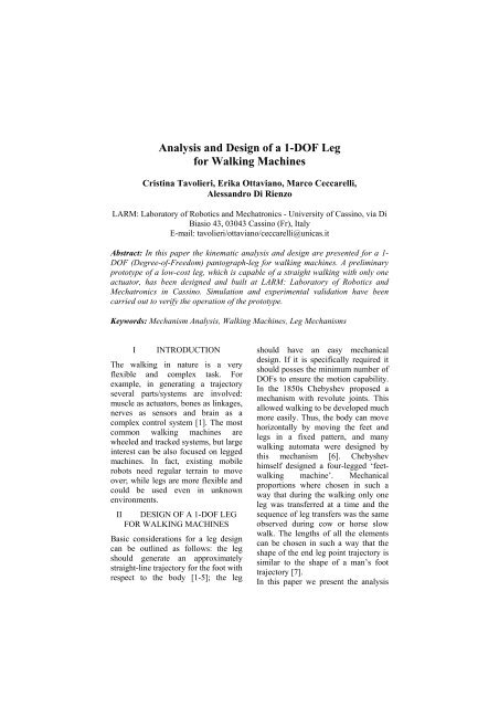
Abstract: In this paper the kinematic analysis <strong>and</strong> design are presented <strong>for</strong> a 1-<br />
<strong>DOF</strong> (Degree-<strong>of</strong>-Freedom) pantograph-leg <strong>for</strong> walking machines. A preliminary<br />
prototype <strong>of</strong> a low-cost leg, which is capable <strong>of</strong> a straight walking with only one<br />
actuator, has been designed <strong>and</strong> built at LARM: Laboratory <strong>of</strong> Robotics <strong>and</strong><br />
Mechatronics in Cassino. Simulation <strong>and</strong> experimental validation have been<br />
carried out to verify the operation <strong>of</strong> the prototype.<br />
Keywords: Mechanism <strong>Analysis</strong>, <strong>Walking</strong> <strong>Machines</strong>, <strong>Leg</strong> Mechanisms<br />
I INTRODUCTION<br />
The walking in nature is a very<br />
flexible <strong>and</strong> complex task. For<br />
example, in generating a trajectory<br />
several parts/systems are involved:<br />
muscle as actuators, bones as linkages,<br />
nerves as sensors <strong>and</strong> brain as a<br />
complex control system [1]. The most<br />
common walking machines are<br />
wheeled <strong>and</strong> tracked systems, but large<br />
interest can be also focused on legged<br />
machines. In fact, existing mobile<br />
robots need regular terrain to move<br />
over; while legs are more flexible <strong>and</strong><br />
could be used even in unknown<br />
environments.<br />
II DESIGN OF A 1-<strong>DOF</strong> LEG<br />
FOR WALKING MACHINES<br />
Basic considerations <strong>for</strong> a leg design<br />
can be outlined as follows: the leg<br />
should generate an approximately<br />
straight-line trajectory <strong>for</strong> the foot with<br />
respect to the body [1-5]; the leg<br />
should have an easy mechanical<br />
design. If it is specifically required it<br />
should posses the minimum number <strong>of</strong><br />
<strong>DOF</strong>s to ensure the motion capability.<br />
In the 1850s Chebyshev proposed a<br />
mechanism with revolute joints. This<br />
allowed walking to be developed much<br />
more easily. Thus, the body can move<br />
horizontally by moving the feet <strong>and</strong><br />
legs in a fixed pattern, <strong>and</strong> many<br />
walking automata were designed by<br />
this mechanism [6]. Chebyshev<br />
himself designed a four-legged ‘feetwalking<br />
machine’. Mechanical<br />
proportions where chosen in such a<br />
way that during the walking only one<br />
leg was transferred at a time <strong>and</strong> the<br />
sequence <strong>of</strong> leg transfers was the same<br />
observed during cow or horse slow<br />
walk. The lengths <strong>of</strong> all the elements<br />
can be chosen in such a way that the<br />
shape <strong>of</strong> the end leg point trajectory is<br />
similar to the shape <strong>of</strong> a man’s foot<br />
trajectory [7].<br />
In this paper we present the analysis
<strong>and</strong> design <strong>of</strong> a leg, which is composed<br />
by a Chebyshev mechanism <strong>and</strong><br />
pantograph. Its main characteristic is<br />
to posses only 1-<strong>DOF</strong>, with many<br />
advantages in terms <strong>of</strong> cost <strong>and</strong><br />
operation.<br />
A leg design has been proposed to be<br />
low-cost <strong>and</strong> easy in operation <strong>and</strong> it<br />
has been also improved in its<br />
mechanical design by adding two<br />
articulated parallelograms that make<br />
the foot <strong>of</strong> the robot always parallel<br />
with respect to the ground.<br />
III A KINEMATIC ANALYSIS<br />
A Kinematic analysis has been carried<br />
out in order to evaluate <strong>and</strong> simulate<br />
per<strong>for</strong>mances <strong>and</strong> operations <strong>of</strong> the leg<br />
system. A fixed reference system CXY<br />
has been considered attached at point<br />
C, as shown in Fig. 1. The position <strong>of</strong><br />
point B with respect to CXY frame can<br />
be evaluated as a function <strong>of</strong> the input<br />
crank angle α <strong>and</strong> kinematic<br />
parameters <strong>of</strong> the Chebyshev<br />
mechanism LEBDC in the <strong>for</strong>m<br />
X B = – a + m cosα + (c+f) cosα<br />
Y B = – m sinα – (c+f) sinθ (1)<br />
in which<br />
2 2 2 1/2<br />
−1<br />
senα − (sen α + B − D )<br />
θ = 2tan<br />
B + D<br />
(2)<br />
Coefficients B <strong>and</strong> D can be obtained<br />
by considering the closure equation <strong>of</strong><br />
the five-bar linkage CDBGM in Fig. 1.<br />
Thus, one can obtain φ 2 <strong>and</strong> φ 3 angles<br />
in the <strong>for</strong>m<br />
⎛<br />
2 ⎞<br />
−1<br />
⎜ L1<br />
− 4L1L3<br />
⎟<br />
ϕ2<br />
= tan ⎜−<br />
L2<br />
−<br />
⎟<br />
2L1<br />
⎝<br />
⎠<br />
⎛<br />
2 ⎞<br />
−1<br />
⎜ K1<br />
− 4K1K3<br />
⎟<br />
ϕ3<br />
= tan ⎜−<br />
K2<br />
−<br />
⎟<br />
2K1<br />
⎝<br />
⎠ (3)<br />
where<br />
Figure 1<br />
A kinematic scheme <strong>for</strong> the 1-<strong>DOF</strong> leg<br />
L 1 = 2 X B z 2 – 2 X M z 2 + X 2 B + X 2 M +<br />
z 2 2 + Y 2 B + Y 2 M – z 2 3 – 2 X B X M –<br />
2 Y B Y M<br />
L 2 = – 4 Y B z 2 +4 Y M z 2 (4)<br />
L 3 = – 2 X B z 2 +2 X M z 2 + X 2 B + X 2 M +<br />
z 2 2 + Y 2 2<br />
B + Y M<br />
K 1 = – 2 X B z 3 +2 X M z 3 + X B 2 + X M 2 +<br />
z 3 2 + Y B 2 + Y M 2 – z 2 2 – 2 X B X M –<br />
2 Y B Y M<br />
K 2 = – 4 Y B z 3 +4 Y M z 3 (5)<br />
K 3 = 2 X B z 3 – 2 X M z 3 + X B 2 + X M 2 +<br />
z 3 2 + Y B 2 + Y M<br />
2<br />
Consequently, the transmission angles<br />
γ <strong>and</strong> γ 2 shown in Fig. 1 can be<br />
evaluated as γ =θ+φ 2 , <strong>and</strong> γ 2 =φ 2 +φ 3 .<br />
The position <strong>of</strong> A with respect to the<br />
fixed frame can be given as<br />
X A = X B – (z 2 +z 4 ) cosφ 2 + (z 3 +z 5 ) cosφ 3<br />
Y A = Y B – (z 2 +z 4 ) sinφ 2 – (z 3 +z 5 ) sinφ 3<br />
(6)
Figure 2 shows a numerical simulation<br />
<strong>for</strong> trajectories <strong>of</strong> points A <strong>and</strong> B as<br />
function <strong>of</strong> the LE input crank angle.<br />
The velocity <strong>of</strong> point A can be<br />
evaluated as<br />
X<br />
A = X<br />
B + ϕ<br />
2 (z 2 + z 4 ) sin ϕ2<br />
+<br />
− ϕ<br />
3 (z 3 + z 5 ) sin ϕ3<br />
Y<br />
A = Y<br />
B − ϕ<br />
2 (z 2 + z 4 ) cos ϕ2<br />
+<br />
− ϕ<br />
3 (z 3 + z 5 ) cos ϕ3<br />
(7)<br />
in which the velocity <strong>of</strong> point B can be<br />
obtained by differentiating Eq. (1) with<br />
respect to time.<br />
The acceleration <strong>of</strong> point A, with<br />
respect to the fixed frame can be<br />
obtained as<br />
2<br />
X<br />
A = X<br />
B + ϕ<br />
2 (z 2 + z 4 ) cos ϕ2<br />
+<br />
+ ϕ<br />
(z + z ) sin ϕ +<br />
− ϕ<br />
− ϕ<br />
2<br />
2<br />
3<br />
3<br />
(z<br />
(z<br />
2<br />
2<br />
3<br />
2<br />
3<br />
3<br />
4<br />
5<br />
+ z ) sin ϕ<br />
5<br />
2<br />
+ z ) cos ϕ +<br />
2<br />
Y<br />
A = Y<br />
B + ϕ<br />
2 (z 2 + z 4 ) sin ϕ2<br />
+<br />
− ϕ<br />
(z + z ) cos ϕ +<br />
2<br />
4<br />
3<br />
3<br />
2<br />
(8)<br />
+ ϕ<br />
(z 3 + z 5 ) sin ϕ3<br />
+<br />
− ϕ<br />
3 (z 3 + z 5 ) cos ϕ3<br />
(9)<br />
The proposed analysis has been<br />
considered <strong>for</strong> numerical simulations.<br />
In particular, numerical results have<br />
been obtained without considering the<br />
leg’s interaction with the ground.<br />
Figures 3 <strong>and</strong> 4 show numerical results<br />
when the design parameters are given<br />
in Table 1.<br />
It is worth to note that an amplification<br />
factor equal to 2 has been chosen to<br />
reproduce a suitable foot trajectory, as<br />
shown in Fig. 2.<br />
In particular, Fig. 3 shows numerical<br />
results <strong>for</strong> the transmission angles<br />
evaluated as functions <strong>of</strong> the input<br />
crank angle α. Figure 4 shows results<br />
<strong>of</strong> the numerical simulation <strong>for</strong> the<br />
velocity <strong>of</strong> point A that has been<br />
obtained when the angular velocity ω<br />
<strong>of</strong> the input crank is chosen with a<br />
constant value equal to 2.3 rad/s.<br />
Table 1<br />
<strong>Design</strong> parameters in mm <strong>for</strong> the kinematic<br />
model <strong>of</strong> Fig. 1<br />
c=f=d=62.5 a=z 2 =50.0<br />
b 1 =75.0 b 2 =150.0<br />
m=25.0 h=230.0<br />
z 2 =50.0 z 3 =z 6 =110.0<br />
z 4 =220.0 z 5 =z 7 =100.0<br />
Figure 2<br />
Numerical simulation <strong>for</strong> trajectories <strong>of</strong> points A<br />
<strong>and</strong> B <strong>of</strong> the leg when design parameters are<br />
given in Table 1<br />
(a)<br />
(b)<br />
Figure 3<br />
Numerical simulation <strong>for</strong> the transmission<br />
angles in degrees: a) angle γ 1 ; b) angle γ 2
(a)<br />
(b)<br />
Figure 4<br />
Numerical simulation <strong>for</strong> the leg: a) velocity<br />
X A Y <br />
; b) velocity A<br />
Figure 5 shows numerical simulation<br />
<strong>of</strong> the acceleration <strong>of</strong> point A when a<br />
constant angular velocity has been<br />
considered.<br />
(a)<br />
(b)<br />
Figure 5<br />
Simulation <strong>for</strong> the walking characteristics <strong>of</strong> the<br />
X<br />
proposed 1-<strong>DOF</strong> leg: a) acceleration<br />
A ;<br />
Y<br />
b) acceleration A .<br />
IV<br />
BUILT PROTOTYPES<br />
Prototypes <strong>of</strong> low-cost legs have been<br />
built at LARM: Laboratory <strong>of</strong><br />
Robotics <strong>and</strong> Mechatronics in Cassino,<br />
as based on the proposed 1-<strong>DOF</strong><br />
kinematic scheme. The built<br />
prototypes are shown in Figs. 6 <strong>and</strong> 7.<br />
Experimental tests have been carried<br />
out with the leg. It has been tested by<br />
considering two operation modes,<br />
‘walker’ <strong>and</strong> ‘ostrich’ modes [8],<br />
which can be obtained by a counterclockwise<br />
motion <strong>of</strong> the input crank,<br />
<strong>and</strong> by a clockwise motion <strong>of</strong> the input<br />
crank.<br />
The prototype in Fig. 7 has been<br />
obtained by considering a double<br />
articulated parallelogram <strong>and</strong> passive<br />
prismatic guides, which allow keeping<br />
the foot <strong>of</strong> the robot always parallel<br />
with the ground. Current development<br />
<strong>of</strong> this work is the enhancement <strong>of</strong> a<br />
biped walking robot built at LARM [9,<br />
10] <strong>and</strong> shown in Fig. 8.
(a)<br />
(a)<br />
(b)<br />
Figure 6<br />
Built prototype <strong>of</strong> the leg based on the scheme<br />
<strong>of</strong> Fig. 1: a) the design; b) a prototype<br />
(b)<br />
Figure 7<br />
Built prototype <strong>of</strong> the leg with the double<br />
parallelogram: a) the design; b) a prototype
Figure 8<br />
Prototype <strong>of</strong> a biped walking robot at LARM<br />
Conclusion<br />
In this paper a kinematic analysis <strong>and</strong><br />
the design are presented <strong>for</strong> a 1-<strong>DOF</strong><br />
leg <strong>for</strong> walking machines. Numerical<br />
simulations are reported to show the<br />
feasibility <strong>of</strong> the mechanical design<br />
<strong>and</strong> leg operation. Two prototypes <strong>of</strong><br />
the leg have been built <strong>and</strong> tested at<br />
LARM. Current development <strong>of</strong> this<br />
work is to design <strong>and</strong> build a new lowcost,<br />
easy operation biped walking<br />
machine.<br />
References<br />
[1] Morecki A.: Biomechanical<br />
Modeling <strong>of</strong> Human <strong>Walking</strong>, 9 th<br />
World Congr. on the Theory <strong>of</strong><br />
Mach. <strong>and</strong> Mech., Milan, Vol. 3,<br />
1995, pp. 2400-2403<br />
[2] Karsten Berns web page:<br />
www.fzi.de/ids/WMC/walking_<br />
machines_katalog/walking_mach<br />
ines_katalog.html<br />
[3] Hirose S., Kunieda O.:<br />
Generalized St<strong>and</strong>ard Foot<br />
Trajectory <strong>for</strong> a Quadruped<br />
<strong>Walking</strong> Vehicle, The Int. Jnl. <strong>of</strong><br />
Rob. Research, Vol. 10, No. 1,<br />
1991, pp. 3-12<br />
[4] Yoneda K.: <strong>Design</strong> <strong>of</strong> Non-Bio-<br />
Mimetic Walker with Fewer<br />
Actuators, 4 th CLAWAR,<br />
Karlsruhe, 2001, pp. 115-126<br />
[5] Song S. M., Lee J. K, Waldron K.<br />
J.: Motion Study <strong>of</strong> Two <strong>and</strong><br />
Three Dimensional Pantograph<br />
Mechanisms, Mech. <strong>and</strong> Mach.<br />
Theory, 1987<br />
[6] M. H. Raibert: <strong>Leg</strong>ged Robots<br />
That Balance. MIT Press, 1986,<br />
pp. 3-14<br />
[7] F. Pfeiffer, T. Zielinska:<br />
<strong>Walking</strong>: Biological <strong>and</strong><br />
Technological Aspects,<br />
International Centre <strong>for</strong><br />
Mechanical Sciences Courses <strong>and</strong><br />
Lectures n. 467, Springer Wien<br />
New York, 2004, pp. 1-29<br />
[8] Di Rienzo A.: Numerical <strong>and</strong><br />
Experimental Analyses <strong>of</strong><br />
Mechanisms <strong>for</strong> Mobile Robots,<br />
Master Thesis, LARM,<br />
University <strong>of</strong> Cassino, Cassino,<br />
2005 (in Italian)<br />
[9] Tavolieri C.: <strong>Design</strong>, Simulation<br />
<strong>and</strong> Construction <strong>of</strong> a Biped<br />
<strong>Walking</strong> Robot, Master Thesis,<br />
LARM, University Cassino,<br />
Cassino, 2004 (in Italian)<br />
[10] Ottaviano E., Ceccarelli M.,<br />
Tavolieri C.: Kinematic <strong>and</strong><br />
Dynamic Analyses <strong>of</strong> a<br />
Pantograph-<strong>Leg</strong> <strong>for</strong> a Biped<br />
<strong>Walking</strong> Machine, 7 th CLAWAR,<br />
Madrid 2004, pp. 561-568