Basic Concrete w/Poured Beams - BlazeFrame
Basic Concrete w/Poured Beams - BlazeFrame
Basic Concrete w/Poured Beams - BlazeFrame

Create successful ePaper yourself
Turn your PDF publications into a flip-book with our unique Google optimized e-Paper software.
Project Submittal –<strong>Basic</strong> <strong>Concrete</strong> w/<strong>Poured</strong> <strong>Beams</strong><br />
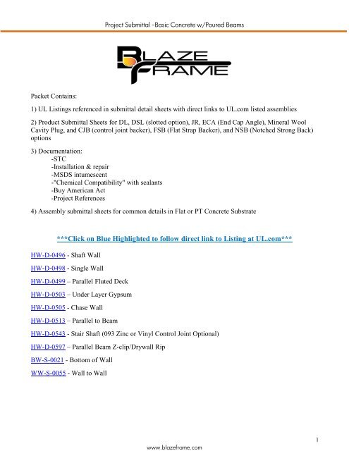
Packet Contains:<br />
1) UL Listings referenced in submittal detail sheets with direct links to UL.com listed assemblies<br />
2) Product Submittal Sheets for DL, DSL (slotted option), JR, ECA (End Cap Angle), Mineral Wool<br />
Cavity Plug, and CJB (control joint backer), FSB (Flat Strap Backer), and NSB (Notched Strong Back)<br />
options<br />
3) Documentation:<br />
-STC<br />
-Installation & repair<br />
-MSDS intumescent<br />
-"Chemical Compatibility" with sealants<br />
-Buy American Act<br />
-Project References<br />
4) Assembly submittal sheets for common details in Flat or PT <strong>Concrete</strong> Substrate<br />
***Click on Blue Highlighted to follow direct link to Listing at UL.com***<br />
HW-D-0496 - Shaft Wall<br />
HW-D-0498 - Single Wall<br />
HW-D-0499 – Parallel Fluted Deck<br />
HW-D-0503 – Under Layer Gypsum<br />
HW-D-0505 - Chase Wall<br />
HW-D-0513 – Parallel to Beam<br />
HW-D-0543 - Stair Shaft (093 Zinc or Vinyl Control Joint Optional)<br />
HW-D-0597 – Parallel Beam Z-clip/Drywall Rip<br />
BW-S-0021 - Bottom of Wall<br />
WW-S-0055 - Wall to Wall<br />
www.blazeframe.com<br />
1
Project Submittal –<strong>Basic</strong> <strong>Concrete</strong> w/<strong>Poured</strong> <strong>Beams</strong><br />
Product Submittal<br />
PS1 - “DL” (Deep Leg) Profiles with two solid legs<br />
Composite Fire Stop/Framing for use in up to 3 hr rated wall assemblies. Provides 100% unencumbered joint<br />
protection accommodates up to 3" overall movement with level III (seismic) certification. Minimum G40 (25ga)<br />
and G60 (18ga and heavier) coating with two solid legs supporting “free floating” studs per listed assemblies in<br />
UL Fire Resistance Directory.<br />
(I)<br />
(L)<br />
Widths (W)<br />
250 (2 1/2")<br />
362 (3 5/8")<br />
400 (4")<br />
600 (6")<br />
800 (8")<br />
Mil (Ga)<br />
.018 (25)<br />
.030 (20)<br />
.033 (20)<br />
.043 (18)<br />
.054 (16)<br />
.068 (14)<br />
Part Identification<br />
Example: 400DL2 - 30<br />
400 DL 2 - 30<br />
Track Width<br />
Profile<br />
Series<br />
Gauge<br />
1 - Series (Fire Stop One Side) 2 - Series (Fire Stop Both Sides)<br />
(W)<br />
(W)<br />
(L) (L) (L) (L)<br />
Profile<br />
DLE<br />
DL<br />
DLW<br />
DLX<br />
DLZ<br />
Leg Length<br />
(L)<br />
Strip Width<br />
(I)<br />
Slot Height<br />
(S)<br />
Joint<br />
Protection<br />
2.00" .75" N/A<br />
.50"<br />
2.00"<br />
2.00"<br />
2.50"<br />
3.00"<br />
1.00"<br />
1.25"<br />
1.75"<br />
2.25"<br />
N/A<br />
N/A<br />
N/A<br />
N/A<br />
.75"<br />
1.00"<br />
1.50"<br />
2.00"<br />
N/A 3.00"<br />
DLY 4.00" 3.25"<br />
UL, ASTM & Code Standards<br />
Leed Points<br />
UL2079 & ULC S115-M95<br />
MR 2.1 & 2.2 - Construction Waste: up to 2pts<br />
ASTM E814, E1966, E2837<br />
MR 4.1 & 4.2 - Recycled Content: up to 2 pts<br />
A1003, A653, A924, C645, C754, C955 MR 5.1 & 5.2 - Regional Proximity<br />
AISI 2004 NAS<br />
EQ 4.1 - Low Emitting Materials<br />
2009 IBC & 2010 CBC EQ 9 - Enhanced Acoustical<br />
Phone: (425) 869-2811 Fax: (425) 869-2300<br />
www.blazeframe.com<br />
2
Project Submittal –<strong>Basic</strong> <strong>Concrete</strong> w/<strong>Poured</strong> <strong>Beams</strong><br />
Product Submittal<br />
PS7 - “DSL” (Slotted Both Sides) Profiles with two slotted legs<br />
Composite Fire Stop/Framing for use in up to 3 hr rated wall assemblies. Provides 100% unencumbered joint<br />
protection accommodates up to 1 1/2” overall movement with level III (seismic) certification. Minimum G40<br />
(25ga) and G60 (18ga and heavier) coating two legs with slots spaced 1” O/C for attachment of studs per listed<br />
assemblies in UL Fire Resistance Directory.<br />
(I)<br />
(S)<br />
(L)<br />
Widths (W)<br />
250 (2 1/2")<br />
362 (3 5/8")<br />
400 (4")<br />
600 (6")<br />
800 (8")<br />
1.00" .25"<br />
Mil (Ga)<br />
.018 (25)<br />
.030 (20)<br />
.033 (20)<br />
.043 (18)<br />
.054 (16)<br />
.068 (14)<br />
Fastener mid-height<br />
of exposed slot<br />
Part Identification<br />
Example:<br />
362<br />
Track Width<br />
Profile<br />
362DSL2-30<br />
DSL<br />
2<br />
Series<br />
- 30<br />
Gauge<br />
1 - Series (Fire Stop One Side) 2 - Series (Fire Stop Both Sides)<br />
(W)<br />
(W)<br />
(L) (L) (L) (L)<br />
Profile<br />
DSLE<br />
Leg Length<br />
(L)<br />
2.00"<br />
Strip Width<br />
(I)<br />
.75"<br />
Slot Height<br />
(S)<br />
1.00"<br />
Joint<br />
Protection<br />
.50"<br />
DSL<br />
DSLW<br />
DSLX<br />
3.00"<br />
3.00"<br />
4.00"<br />
1.00"<br />
1.25"<br />
1.75"<br />
1.50"<br />
1.50"<br />
2.00"<br />
.75"<br />
1.00"<br />
1.50"<br />
UL, ASTM & Code Standards<br />
Leed Points<br />
UL2079 & ULC S115-M95<br />
MR 2.1 & 2.2 - Construction Waste: up to 2pts<br />
ASTM E814, E1966, E2837<br />
MR 4.1 & 4.2 - Recycled Content: up to 2 pts<br />
A1003, A653, A924, C645, C754, C955 MR 5.1 & 5.2 - Regional Proximity<br />
AISI 2004 NAS<br />
EQ 4.1 - Low Emitting Materials<br />
2009 IBC & 2010 CBC EQ 9 - Enhanced Acoustical<br />
www.blazeframe.com<br />
3
Project Submittal –<strong>Basic</strong> <strong>Concrete</strong> w/<strong>Poured</strong> <strong>Beams</strong><br />
Phone: (425) 869-2811 Fax: (425) 869-2300<br />
Product Submittal<br />
PS27 - <strong>BlazeFrame</strong> “JR” profiles with one short (front) and one long (back) leg<br />
Composite Fire Stop/Framing for use in up to 3 hr rated shaft wall assemblies. Provides 100% unencumbered<br />
joint protection accommodating up to 1 1/2" overall movement with level III (seismic) certification. Minimum<br />
G40 (20ga) and G60 (18ga and heavier) coating with one leg (front) having intumescent per listed assemblies in<br />
UL Fire Resistance Directory.<br />
(I)<br />
(FL)<br />
(BL)<br />
Widths (W)<br />
250 (2 1/2")<br />
400 (4")<br />
600 (6")<br />
Gauge<br />
.030 (20)<br />
.033 (20)<br />
.043 (18)<br />
.054 (16)<br />
Pat. Pend<br />
Part Identification<br />
Example: 400JR1 - 30<br />
400 JR1 - 30<br />
Track Width Profile Gauge<br />
JR1 - Series (Fire Stop "short leg")<br />
(W)<br />
(I) (FL)<br />
(FL) (BL)<br />
(BL)<br />
Profile Front Leg Back Leg Strip Width Joint<br />
JRE1 2.00" 3.00"<br />
(I)<br />
.75"<br />
Protection<br />
.50"<br />
JR1<br />
JRW1<br />
JRX1<br />
2.00"<br />
2.00"<br />
2.00"<br />
3.00"<br />
3.00"<br />
3.00"<br />
1.00"<br />
1.25"<br />
1.75"<br />
.75"<br />
1.00"<br />
1.50"<br />
UL, ASTM & Code Standards<br />
Leed Points<br />
UL2079 & ULC S115-M95<br />
MR 2.1 & 2.2 - Construction Waste: up to 2pts<br />
ASTM E814, E1966, E2837<br />
MR 4.1 & 4.2 - Recycled Content: up to 2 pts<br />
A1003, A653, A924, C645, C754, C955 MR 5.1 & 5.2 - Regional Proximity<br />
AISI 2004 NAS<br />
EQ 4.1 - Low Emitting Materials<br />
2009 IBC & 2010 CBC EQ 9 - Enhanced Acoustical<br />
www.blazeframe.com<br />
4
Project Submittal –<strong>Basic</strong> <strong>Concrete</strong> w/<strong>Poured</strong> <strong>Beams</strong><br />
Phone: (425) 869-2811 Fax: (425) 869-2300<br />
Product Profile Dimensions<br />
Product Submittal<br />
PS42 - “ECA” (End Cap Angle) to Cap Track Ends<br />
Composite Fire Stop/Framing for use in up to 3 hr rated wall assemblies. Provides 100%<br />
unencumbered joint protection accommodates up to 3” overall movement with level III (seismic)<br />
certification. Minimum G40 (20ga) and G60 (18ga and heavier) coating installed in end of track<br />
profiles (exterior corners) with fire stop facing outward towards rated joints.<br />
(I)<br />
(L)<br />
Pat. Pend.<br />
3.00"<br />
(L)<br />
(I)<br />
(W)<br />
.25" .25"<br />
Width (W)<br />
362<br />
400<br />
600<br />
800<br />
Gauge<br />
.030 (20)<br />
.043 (18)<br />
.054 (16)<br />
Part Identification<br />
Example: 362ECA-30<br />
Width<br />
362 ECA - 30<br />
Profile<br />
Gauge<br />
Profile Leg Length<br />
(L)<br />
Strip Width<br />
(I)<br />
Slot Height<br />
(S)<br />
Joint<br />
Protection<br />
ECA 2.00" 1.00" N/A .75"<br />
ECAW<br />
ECAX<br />
ECAZ<br />
2.00"<br />
2.50"<br />
3.00"<br />
1.25"<br />
1.75"<br />
2.25"<br />
N/A<br />
N/A<br />
N/A<br />
1.00"<br />
1.50"<br />
2.00"<br />
ECAY 4.00" 3.25" N/A 3.00"<br />
UL, ASTM & Code Standards<br />
Leed Points<br />
UL2079 & ULC S115-M95<br />
MR 2.1 & 2.2 - Construction Waste: up to 2pts<br />
ASTM E814, E1966, E2837<br />
MR 4.1 & 4.2 - Recycled Content: up to 2 pts<br />
A1003, A653, A924, C645, C754, C955 MR 5.1 & 5.2 - Regional Proximity<br />
AISI 2004 NAS<br />
EQ 4.1 - Low Emitting Materials<br />
2009 IBC & 2010 CBC EQ 9 - Enhanced Acoustical<br />
Phone: (425) 869-2811 Fax: (425) 869-2300<br />
www.blazeframe.com<br />
5
Project Submittal –<strong>Basic</strong> <strong>Concrete</strong> w/<strong>Poured</strong> <strong>Beams</strong><br />
Product Submittal<br />
PS37 - Shaft Wall Cavity Plugs – Preformed Mineral Wool<br />
Mineral Wool preformed to wall cavity widths for protection of joints with a 4.0 lbs/ft3 density. Profiles are used<br />
to fill and protect joints occurring in shaft wall cavities.<br />
Stock Lengths: 24"<br />
SWCP-250<br />
SWCP-400<br />
SWCP-600<br />
3.50" 5.50"<br />
3.50"<br />
4.00"<br />
4.00"<br />
2.00"<br />
www.blazeframe.com<br />
6
Project Submittal –<strong>Basic</strong> <strong>Concrete</strong> w/<strong>Poured</strong> <strong>Beams</strong><br />
Product Product Profile Submittal Dimensions<br />
PS44 - “CJB” profiles for Protection of Control Joints<br />
Composite Fire Stop/Control Joint Backer Profiles for use to protect Architectural design joints (optional<br />
control joint over gap) for up to 2 hr rated assemblies. Profile sections are fabricated from hot-dipped<br />
galvanized steel complying with ASTM A653 with a minimum G40 (25ga). Profiles comply with ASTM<br />
C645 and provide a metal profile which support intumescent materials located inside and spanning gap<br />
between opposing drywall edges at control joint locations.<br />
1.00"<br />
Intumescent<br />
1.25" .75" 1.25"<br />
Part #<br />
Intumescent<br />
Width<br />
Profile<br />
Width<br />
Gauge<br />
CJB-18 1.25" 3.25" .018<br />
UL, ASTM & Code Standards<br />
Leed Points<br />
UL263, E814,<br />
MR 2.1 & 2.2 - Construction Waste: up to 2pts<br />
A1003, A653, A924, C645, C754, C955 MR 4.1 & 4.2 - Recycled Content: up to 2 pts<br />
AISI 2004 NAS<br />
MR 5.1 & 5.2 - Regional Proximity<br />
2006 & 2009 IBC EQ 4.1 - Low Emitting Materials<br />
2010 CBC EQ 9 - Enhanced Acoustical<br />
Phone: (425) 869-2811 Fax: (425) 869-2300<br />
www.blazeframe.com<br />
7
Project Submittal –<strong>Basic</strong> <strong>Concrete</strong> w/<strong>Poured</strong> <strong>Beams</strong><br />
Product Submittal<br />
PS20 - “FSB” profiles for Protection of Reveal and Control Joints<br />
Composite Fire Stop/Flat strap Profiles for use to protect Architectural design joints (drywall reveal mold or<br />
control joint over gap) for up to 2 hr rated assemblies. Profile sections are fabricated from hot-dipped galvanized<br />
steel complying with ASTM A653 with a minimum G40 (20ga) and G60 (18ga and heavier) coating. Profiles<br />
comply with ASTM C645 and provide a flat strap metal supporting fire stop materials.<br />
"IW"<br />
"FSW"<br />
Pat. Pend.<br />
Part #<br />
Intumescent<br />
Width "IW"<br />
Flat Strap<br />
Width "FSW"<br />
Gauge<br />
"FSW"<br />
"IW"<br />
FSB075<br />
FSB100<br />
0.75"<br />
1.00"<br />
3.00"<br />
3.00"<br />
.030<br />
.030<br />
FSB125 1.25"<br />
3.00"<br />
.030<br />
UL, ASTM & Code Standards<br />
Leed Points<br />
UL2079, E814, E1966, ULC S115-M95<br />
MR 2.1 & 2.2 - Construction Waste: up to 2pts<br />
ASTM E814, E1966<br />
MR 4.1 & 4.2 - Recycled Content: up to 2 pts<br />
A1003, A653, A924, C645, C754, C955 MR 5.1 & 5.2 - Regional Proximity<br />
AISI 2004 NAS<br />
EQ 4.1 - Low Emitting Materials<br />
2009 IBC & 2010 CBC EQ 9 - Enhanced Acoustical<br />
Phone: (425) 869-2811 Fax: (425) 869-2300<br />
www.blazeframe.com<br />
8
Project Submittal –<strong>Basic</strong> <strong>Concrete</strong> w/<strong>Poured</strong> <strong>Beams</strong><br />
Product Submittal<br />
www.blazeframe.com<br />
9
Project Submittal –<strong>Basic</strong> <strong>Concrete</strong> w/<strong>Poured</strong> <strong>Beams</strong><br />
Product Submittal<br />
www.blazeframe.com<br />
10
Project Submittal –<strong>Basic</strong> <strong>Concrete</strong> w/<strong>Poured</strong> <strong>Beams</strong><br />
Product Submittal<br />
www.blazeframe.com<br />
11
[Type text]<br />
Project Submittal –<strong>Basic</strong> <strong>Concrete</strong> w/<strong>Poured</strong> <strong>Beams</strong><br />
<strong>BlazeFrame</strong> Benefits<br />
Intumescent "gasket" Joint Protection<br />
Direct Attachment - No Caulk at Substrate<br />
Reduced Sound Transfer - No Exposed Steel<br />
Exposed Head of Wall and Deflection Gaps<br />
Level III Dynamic Cycle (seismic) Rated<br />
No Joint Fatigue - Lifetime Indefinite<br />
Protection<br />
NVLAP accredited -ASTM E90-04<br />
Western Electro- Acoustic Laboratory<br />
Reports Available Upon Request<br />
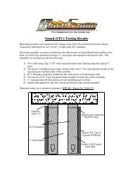
<strong>BlazeFrame</strong> Tested Wall Assemblies<br />
1/2" to 3/4" Exposed Deflection Gaps<br />
5/8" Type X Gypsum Sheathing<br />
3 1/2" Fiberglass Insulation Cavity Fill<br />
STC - 52<br />
Unbalanced - (Report # TL 13-223)<br />
STC - 56<br />
Balanced - (Report #TL 13-229)<br />
STC - 66<br />
Unbalanced - (Report #TL 13-229)<br />
STC - 67<br />
Balanced - (Report #TL 13-230)<br />
www.blazeframe.com<br />
12
AC23 - Installation and Manufacturer Recommendations<br />
Project Submittal –<strong>Basic</strong> <strong>Concrete</strong> w/<strong>Poured</strong> <strong>Beams</strong><br />
Installation/Training, Recommendations, and Repair<br />
Installation/Training<br />
1) Select and install profile to accommodate overall movement and wall framing requirements<br />
2) Attach with approved power actuated or mechanical fasteners per Engineer of Record<br />
3) Profiles (intersecting or aligned) in continuous contact with one another<br />
4) Overlap intumescent with sheathing per UL Listings or <strong>BlazeFrame</strong> "constructability" designs<br />
5) "Chase wall" conditions, locate intumescent in direction of "finished" side of wall<br />
6) Training provided to installer of Blaze Frame product, a onsite review with installers will be<br />
conducted by <strong>BlazeFrame</strong> prior to installation<br />
Recommendations<br />
1) Store <strong>BlazeFrame</strong> products in dry covered area<br />
2) Avoid exposure to excessive heat<br />
3) Install according to UL Listed Assemblies or <strong>BlazeFrame</strong> Constructability designs<br />
4) Compatible with non-solvent based products (caulks, paints, coatings, fire proofing, drywall<br />
"mud")<br />
5) Provide protection of areas adjacent to Blazeframe profile using UL classified applications<br />
6) Penetrations through <strong>BlazeFrame</strong> intumescent must be sealed per UL:<br />
- "non-solvent" mastic materials/caulks may be overlapped onto <strong>BlazeFrame</strong> intumescent<br />
7) Voids adjacent intumescent (deck surface, seams, or embossments and <strong>BlazeFrame</strong>) may be<br />
sealed with a sliver of mineral wool or mastic/caulks per UL to maintain listed L-ratings:<br />
- gaps up to 1/4" (alternate to sliver of mineral wool) mastic/caulks to fill entire gap and<br />
may be overlapped onto <strong>BlazeFrame</strong> intumescent<br />
- gaps greater than 1/4" insert min. 4 pcf mineral wool compressed 33% into and fill void<br />
Repair and Installation Gaps<br />
1) Bare locations on metal profiles where intumescent damaged/torn off:<br />
-clean metal profile "squaring" edges of opposing remaining intumescent<br />
-field apply to match strip width (intumescent provided by <strong>BlazeFrame</strong>)<br />
-apply intumescent covering all surfaces between opposing "squared" edges<br />
2) Gaps 1/8" or smaller between profiles:<br />
-apply UL certified caulk filling gap between opposing edges of intumescent<br />
-alternate: cover gap overlapping both sides min. 1/2" (intumescent by <strong>BlazeFrame</strong>)<br />
3) Gaps up to 1/4" or smaller between profiles:<br />
-cover gap overlapping both sides min. 1/2" (intumescent by <strong>BlazeFrame</strong>)<br />
4) Gaps wider than 1/4":<br />
-install patch per <strong>BlazeFrame</strong> document AC20, AC13, or AC14<br />
www.blazeframe.com<br />
13
AC24 - Intumescent Properties<br />
Project Submittal –<strong>Basic</strong> <strong>Concrete</strong> w/<strong>Poured</strong> <strong>Beams</strong><br />
1. Product Description<br />
A strip of highly intumescent<br />
fire stop material affixed to metal profiles<br />
When exposed to heat, this product<br />
expands and forms a hard char to seal<br />
off joint (gap) preventing passage of flames,<br />
temperature pass through, and hot gases.<br />
2. Material Properties<br />
Asbestos Fillers: None<br />
Solvents: None<br />
Hazardous Ingredients: None<br />
Thickness: 2 mm<br />
Width: Per <strong>BlazeFrame</strong> Profile<br />
Activation of Intumescence:<br />
3. Testing Data<br />
It has been tested as a dynamic and static<br />
joint protection fire stop sealant to ASTM E-<br />
814, UL 1479, and UL 2079. Complies to<br />
Required Environmental Exposure Testing<br />
of Accelerated Aging and High Humidity as<br />
per UL 1479 Fire Test of Through-<br />
Penetration Firestops.<br />
Degree of intumescence per DIN standard<br />
≥18x with weight imposed<br />
≥ 37x free intumescing<br />
ASTM E 84, UL 723 Tunnel Test<br />
Flame Spread 5<br />
Smoke Index 5<br />
Expansion Begins 375 ˚F (190˚C)<br />
Expansion Greatest 575 ˚ (302˚ C)<br />
to 1100˚ F (593˚ C)<br />
Color: Black<br />
Exposed Surface: Poly Coating<br />
Freeze-Thaw: Excellent<br />
www.blazeframe.com<br />
14
Project Submittal –<strong>Basic</strong> <strong>Concrete</strong> w/<strong>Poured</strong> <strong>Beams</strong><br />
AC27 - Chemical Compatibility - Sealants<br />
AC27 - Chemical Compatibility with Sealants<br />
<strong>BlazeFrame</strong> steel/intumescent composite joint framing/protection profiles are produced<br />
using a cured intumescent acting as the "fill, void, cavity" materials with a polyester outer<br />
coating. The intumescent portion of the composite profile is chemically compatible with<br />
"non-solvent" based materials (i.e. caulks, mud, paints, fire proofing, etc..) and as such<br />
will be unaffected and not degrade where contact may occur.<br />
Current sealant manufacturer's products verified as non-solvent and compatible with<br />
<strong>BlazeFrame</strong> profiles are:<br />
Rectorseal:<br />
Metacaulk - 1000, 350i, MC 150+, 950, 1100, 1200, 1500<br />
Biostop - 500+, 350i, BF 150+, 700, 750, 800<br />
Flamesafe - FS1900, FS 900+, FS3000<br />
United States Gypsum (USG):<br />
Type AS<br />
Other brand names may be acceptable based on individual manufacturer of specific brand<br />
providing verification of materials being "non-solvent" and will allow/warranty use of<br />
them in applicable conditions.<br />
www.blazeframe.com<br />
15
Project Submittal –<strong>Basic</strong> <strong>Concrete</strong> w/<strong>Poured</strong> <strong>Beams</strong><br />
AC26 - Buy American Act Certification<br />
<strong>BlazeFrame</strong> steel/intumescent composite joint framing/protection profiles are manufactured and<br />
assembled in US facilities:<br />
<br />
<br />
<br />
<br />
<br />
<br />
<br />
Auburn WA.<br />
Bristol, CT<br />
Warren, OH<br />
Dallas, TX<br />
Riverside, CA<br />
Stockton, CA<br />
Baltimore, MD<br />
Profiles include:<br />
1. Steel (approx. 95% weight of composite profiles) having min 32% recycle content and sourced<br />
100% from combination of following US mills:<br />
USS-Posco Industries - Pittsburg, CA<br />
SteelScape - Kalama, WA or Rancho Cucamonga, CA<br />
California Steel Industries (CSI) - Fontana, CA<br />
2. Intumescent (approx. 5% weight of composite profiles) joint protection material is 100%<br />
manufactured in Houston, TX<br />
Additional information covering <strong>BlazeFrame</strong> Industries and all product, certification, and related<br />
information can be accessed at www.blazeframe.com.<br />
www.blazeframe.com<br />
16
Project Submittal –<strong>Basic</strong> <strong>Concrete</strong> w/<strong>Poured</strong> <strong>Beams</strong><br />
Project References East Coast<br />
Project: CUNY/CCNY Advanced Sciences Research Center<br />
Owner: City University of New York (CUNY)<br />
Architect: KPF – Kohn, Pedersen, Fox<br />
GC/Contractor: Skanska Construction – Donaldson Organization<br />
Project: St. Joseph’s Regional Medical/Children’s Addition – (Paterson, NJ)<br />
Owner: St. Joseph’s<br />
Architect: Francis Cauffman Architects<br />
GC/Contractor: Sterling Barnett Little, Inc. – Sloan and Company<br />
Project: Credit Suisse Data Center – (Clifton, NJ)<br />
Owner: Russo Development<br />
Architect: Russo<br />
GC/Contractor: Component Assembly<br />
Project: The Green at Florham Park _ (Florham Park, NJ)<br />
Owner: The Rockefeller Group<br />
Architect: KPF Architects<br />
GC/Contractor: Sloan and Company<br />
Project: International Gem Tower – (New York, NY)<br />
Owner: Extell Development Co.<br />
Architect: Skidmore, Owings & Merrill, LLP<br />
GC/Contractor: Tishman Construction Corp. – Pabco Construction<br />
Project: Mercer County Courthouse – (Trenton, NJ)<br />
Owner: Mercer County<br />
Architect: Vitetta<br />
GC/Contractor: Ernest Bock & Sons – Sloan and Company<br />
Project: JFK Airport Expansion – (New York, NY)<br />
Owner: Port Authority of New York<br />
Architect: Gensler<br />
GC/Contractor: Component Assembly Systems<br />
Project: Campus Center SUNY Farmingdale State College – (Farmingdale, NY)<br />
Owner: SUNY Farmingdale State College<br />
Architect: Kevin Hom & Andrew Goldman Architects<br />
GC/Contractor: Kokolakis Construction – Pabco Construction<br />
www.blazeframe.com<br />
17
Project Submittal –<strong>Basic</strong> <strong>Concrete</strong> w/<strong>Poured</strong> <strong>Beams</strong><br />
Project References West Coast<br />
Project: 7 th & Fig mall Renovation – (Los Angeles, CA)<br />
Owner: Brookfield Properties<br />
Architect: Gensler<br />
GC/Contractor: Turner Construction<br />
Project: Camp Pendleton Naval Hospistal - (San Diego, CA)<br />
Owner: US Marine Corp – Camp Pendleton<br />
Architect: HKS<br />
GC/Contractor: Clark/McCarthy – Component West<br />
Project: Torrance Memorial Center New Tower – (Los Angeles, CA)<br />
Owner: Torrance Memorial Medical Center<br />
Architect: HMC Architects<br />
GC/Contractor: McCarthy Building Cos. Inc. – Capparelli/KHS&S<br />
Project: 2201 Westlake – (16 story residential condominium tower) – (Seattle, WA)<br />
Owner: Vulcan Real Estate<br />
Architect: Callison<br />
GC/Contractor: Expert Drywall<br />
Project: Hyatt Regency – (20 story hotel addition) – (Bellevue,WA)<br />
Owner: Kemper Development<br />
Architect: Sclater Partners<br />
GC/Contractor: Anning Johnson<br />
Project: Amazon.com Headquarters (5 story blocks & 2-12 story towers) – (Seattle, WA)<br />
Owner: Vulcan Real Estate<br />
Architect: Callison<br />
GC/Contractor: Expert Drywall & Anning Johnson<br />
Project: Oregon State Hospital (Replacement, Remodel, and Addition) – (Salem, OR)<br />
Owner: State of Oregon<br />
Architect: KMD Architects<br />
GC/Contractor: Performance Contracting Inc.<br />
Project: New Long Beach Courthouse/Gov George Deukmejian Courthouse<br />
Owner: State of California<br />
Architect: AECOM<br />
GC/Contractor: KHS&S<br />
www.blazeframe.com<br />
18
Project Submittal –<strong>Basic</strong> <strong>Concrete</strong> w/<strong>Poured</strong> <strong>Beams</strong><br />
DT1 - Wall Perpendicular Flange Penetration Deflection Joint at Base<br />
Joint Movement Capabilities (MC) / Profile Series design based on UL: HW-D-0498 & 0543<br />
¾” MC - (Stock Series) 1” MC - ("W" Series) 1 1/2” MC - ("X" Series)<br />
2” MC - ("Z" Series) 3" MC - ("Y" Series)<br />
3 4<br />
5<br />
1 2<br />
1. Installed Gap:<br />
- (compression only) = movement capability (MC) of profile<br />
- (compress + extension) = ½ movement capability (MC) of profile<br />
2. <strong>BlazeFrame</strong> profile attach to substrate with approved fastener<br />
3. Drywall installed per U400 or V400 UL designs (same above and below <strong>BlazeFrame</strong>)<br />
4. Min. 25ga stud and track framing installed at gypsum board edges<br />
-span between <strong>BlazeFrame</strong> and deck greater than 24" add vertical stud framing a max 24" O/C<br />
5. Seal edges of gypsum to substrate above <strong>BlazeFrame</strong><br />
-<strong>BlazeFrame</strong> profile or UL approved caulk (static joint no movement required)<br />
UL, ASTM & Code Standards<br />
Leed Points<br />
UL2079 & ULC S115-M95<br />
MR 2.1 & 2.2 - Construction Waste: up to 2pts<br />
ASTM E814, E1966, E2837<br />
MR 4.1 & 4.2 - Recycled Content: up to 2 pts<br />
A1003, A653, A924, C645, C754, C955 MR 5.1 & 5.2 - Regional Proximity<br />
AISI 2004 NAS<br />
EQ 4.1 - Low Emitting Materials<br />
2009 IBC & 2010 CBC EQ 9 - Enhanced Acoustical<br />
Phone: (425) 869-2811 Fax: (425) 869-2300<br />
www.blazeframe.com<br />
19
Project Submittal –<strong>Basic</strong> <strong>Concrete</strong> w/<strong>Poured</strong> <strong>Beams</strong><br />
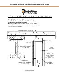
DT2 - Wall Parallel and next to Beam<br />
Joint Movement Capabilities (MC) / Profile Series design based on UL: HW-D-0498 & 0513<br />
¾” MC - (Stock Series) 1” MC - ("W" Series) 1 1/2” MC - ("X" Series)<br />
2” MC - ("Z" Series) 3" MC - ("Y" Series)<br />
Fastener Attachment 24" O/C max.<br />
"Double Tee"<br />
<strong>Concrete</strong> Deck<br />
Installed Gap<br />
(See Notes)<br />
<strong>BlazeFrame</strong> Composite<br />
Track/Fire Stop<br />
1" to 4"<br />
(See Notes)<br />
5/8" Type X<br />
Gypsum Wallboard<br />
Fastener below Flange<br />
Obstruction (max. 24")<br />
(when exists)<br />
Steel Stud<br />
Max 24" O/C<br />
1.Installed Gap (compression only) = movement capability (MC) of profile<br />
2. Installed Gap (compress + extension) = ½ movement capability (MC) of profile<br />
3. Attach to substrate with approved fastener max 24” O.C or per E.O.R.<br />
4. Do not screw drywall or stud to <strong>BlazeFrame</strong> solid leg profile studs "free float"<br />
5. “Slotted” profile metal framing fastener installed center of slot (min. one side)<br />
6. Drywall fasteners 1” to 4" below <strong>BlazeFrame</strong> to accommodate MC or at bottom of obstruction<br />
UL, ASTM & Code Standards<br />
Leed Points<br />
UL2079 & ULC S115-M95<br />
MR 2.1 & 2.2 - Construction Waste: up to 2pts<br />
ASTM E814, E1966, E2837<br />
MR 4.1 & 4.2 - Recycled Content: up to 2 pts<br />
A1003, A653, A924, C645, C754, C955 MR 5.1 & 5.2 - Regional Proximity<br />
AISI 2004 NAS<br />
EQ 4.1 - Low Emitting Materials<br />
2009 IBC & 2010 CBC EQ 9 - Enhanced Acoustical<br />
Phone: (425) 869-2811 Fax: (425) 869-2300<br />
www.blazeframe.com<br />
20
Project Submittal –<strong>Basic</strong> <strong>Concrete</strong> w/<strong>Poured</strong> <strong>Beams</strong><br />
DT3 - Wall Centered Under Beam Overlap Mineral Wool<br />
Joint Movement Capabilities (MC) / Profile Series design based on UL: HW-D-0498 & 0499<br />
1/2” up to 4" MC - (Stock Series)<br />
"Double Tee"<br />
<strong>Concrete</strong> Deck<br />
Fastener Attachment 24" O/C max.<br />
<strong>BlazeFrame</strong> Composite<br />
Track/Fire Stop<br />
Inverted between Substrate<br />
and Deflection Track<br />
Min. 4 pcf Mineral Wool<br />
Compress 33% between<br />
<strong>Concrete</strong> Flange and <strong>BlazeFrame</strong><br />
Deflection Track<br />
1" to 4"<br />
(See Notes)<br />
5/8" Type X<br />
Gypsum Wallboard<br />
Steel Stud<br />
Max 24" O/C<br />
1. Deflection (compression only) = Install gypsum to cover <strong>BlazeFrame</strong> profile<br />
2. Deflection (compress + extension) = Install gypsum ½ of MC requirement above <strong>BlazeFrame</strong><br />
3. Attach to substrate with approved fastener max 24” O.C or per E.O.R.<br />
4. Do not screw drywall or stud to <strong>BlazeFrame</strong> profile<br />
5. Min. 4 pcf mineral wool compressed 33% between substrate flange and <strong>BlazeFrame</strong><br />
6. Drywall fasteners 1” to 4" below Deflection Track to accommodate MC<br />
UL, ASTM & Code Standards<br />
Leed Points<br />
UL2079 & ULC S115-M95<br />
MR 2.1 & 2.2 - Construction Waste: up to 2pts<br />
ASTM E814, E1966, E2837<br />
MR 4.1 & 4.2 - Recycled Content: up to 2 pts<br />
A1003, A653, A924, C645, C754, C955 MR 5.1 & 5.2 - Regional Proximity<br />
AISI 2004 NAS<br />
EQ 4.1 - Low Emitting Materials<br />
2009 IBC & 2010 CBC EQ 9 - Enhanced Acoustical<br />
Phone: (425) 869-2811 Fax: (425) 869-2300<br />
www.blazeframe.com<br />
21
Project Submittal –<strong>Basic</strong> <strong>Concrete</strong> w/<strong>Poured</strong> <strong>Beams</strong><br />
DT4 - Wall Cantilevered Under Beam Drywall Rips<br />
Joint Movement Capabilities (MC) / Profile Series design based on UL: HW-D-0498 & 0503<br />
¾” MC - (Stock Series) 1” MC - ("W" Series) 1 1/2” MC - ("X" Series)<br />
2” MC - ("Z" Series) 3" MC - ("Y" Series)<br />
"Double Tee"<br />
<strong>Concrete</strong> Deck<br />
Fastener Attachment<br />
24" O/C max. 5/8" drywall rips<br />
Installed Gap<br />
(See Notes)<br />
<strong>BlazeFrame</strong> Composite<br />
Track/Fire Stop<br />
5/8" Type X<br />
Gypsum Wallboard<br />
1" to 4"<br />
(See Notes)<br />
Steel Stud<br />
Max 24" O/C<br />
1. Installed Gap (compression only) = movement capability (MC) of profile<br />
2. Installed Gap (compress + extension) = ½ movement capability (MC) of profile<br />
3. Attach to substrate with approved fastener max 24” O.C or per E.O.R.<br />
4. Do not screw drywall or stud to <strong>BlazeFrame</strong> solid leg profile studs "free float"<br />
5. “Slotted” profile metal framing fastener installed center of slot (min. one side)<br />
6. Drywall fasteners 1” to 4" below <strong>BlazeFrame</strong> to accommodate MC or at bottom of obstruction<br />
UL, ASTM & Code Standards<br />
Leed Points<br />
UL2079 & ULC S115-M95<br />
MR 2.1 & 2.2 - Construction Waste: up to 2pts<br />
ASTM E814, E1966, E2837<br />
MR 4.1 & 4.2 - Recycled Content: up to 2 pts<br />
A1003, A653, A924, C645, C754, C955 MR 5.1 & 5.2 - Regional Proximity<br />
AISI 2004 NAS<br />
EQ 4.1 - Low Emitting Materials<br />
2009 IBC & 2010 CBC EQ 9 - Enhanced Acoustical<br />
Phone: (425) 869-2811 Fax: (425) 869-2300<br />
www.blazeframe.com<br />
22
Project Submittal –<strong>Basic</strong> <strong>Concrete</strong> w/<strong>Poured</strong> <strong>Beams</strong><br />
DT5 - Cantilevered Envelope Under Beam Drywall Rips<br />
Joint Movement Capabilities (MC) / Profile Series design based on UL: HW-D-0597<br />
¾” MC - (Stock Series) 1” MC - ("W" Series) 1 1/2” MC - ("X" Series)<br />
2” MC - ("Z" Series) 3" MC - ("Y" Series)<br />
<strong>BlazeFrame</strong> Composite<br />
Track/Fire Stop<br />
1" to 4"<br />
(See Notes)<br />
Fastener Attachment<br />
16" O/C max.<br />
5/8" drywall rips<br />
Steel Stud<br />
Max 24" O/C<br />
<strong>BlazeFrame</strong> "ISA" Profile<br />
min. 16ga angle<br />
Installed Gap<br />
(See Notes)<br />
5/8" Type X<br />
Gypsum Wallboard<br />
1. Installed Gap (compression only) = movement capability (MC) of profile<br />
2. Installed Gap (compress + extension) = ½ movement capability (MC) of profile<br />
3. Attach to substrate with approved fastener max 24” O.C or per E.O.R.<br />
4. Do not screw drywall or stud to <strong>BlazeFrame</strong> solid leg profiles studs "free float"<br />
5. “Slotted” profiles metal framing fastener installed center of slot (min. one side)<br />
6. Drywall fasteners 1” to 4" below <strong>BlazeFrame</strong> to accommodate MC or at bottom of obstruction<br />
UL, ASTM & Code Standards<br />
Leed Points<br />
UL2079 & ULC S115-M95<br />
MR 2.1 & 2.2 - Construction Waste: up to 2pts<br />
ASTM E814, E1966, E2837<br />
MR 4.1 & 4.2 - Recycled Content: up to 2 pts<br />
A1003, A653, A924, C645, C754, C955 MR 5.1 & 5.2 - Regional Proximity<br />
AISI 2004 NAS<br />
EQ 4.1 - Low Emitting Materials<br />
2009 IBC & 2010 CBC EQ 9 - Enhanced Acoustical<br />
Phone: (425) 869-2811 Fax: (425) 869-2300<br />
www.blazeframe.com<br />
23
Project Submittal –<strong>Basic</strong> <strong>Concrete</strong> w/<strong>Poured</strong> <strong>Beams</strong><br />
DT6 - Wall Intersection between <strong>Beams</strong><br />
Joint Movement Capabilities (MC) / Profile Series design based on UL: HW-D-0498 & 0543<br />
¾” MC - (Stock Series) 1” MC - ("W" Series) 1 1/2” MC - ("X" Series)<br />
2” MC - ("Z" Series) 3" MC - ("Y" Series)<br />
Do not attach gypsum<br />
to <strong>BlazeFrame</strong><br />
"Double Tee"<br />
<strong>Concrete</strong> Deck<br />
Fastener Attachment 24" O/C max.<br />
<strong>BlazeFrame</strong> Composite<br />
Track/Fire Stop<br />
1" to 4"<br />
(See Notes)<br />
Steel Stud<br />
Max 24" O/C<br />
5/8" Type X<br />
Gypsum Wallboard<br />
1. Installed Gap (compression only) = movement capability (MC) of profile<br />
2. Installed Gap (compress + extension) = ½ movement capability (MC) of profile<br />
3. Attach to substrate with approved fastener max 24” O.C or per E.O.R.<br />
4. Do not screw drywall or stud to <strong>BlazeFrame</strong> solid leg profile studs "free float"<br />
5. “Slotted” profile metal framing fastener installed center of slot (min. one side)<br />
6. Drywall fasteners 1” to 4" below <strong>BlazeFrame</strong> to accommodate MC or at bottom of obstruction<br />
UL, ASTM & Code Standards<br />
Leed Points<br />
UL2079 & ULC S115-M95<br />
MR 2.1 & 2.2 - Construction Waste: up to 2pts<br />
ASTM E814, E1966, E2837<br />
MR 4.1 & 4.2 - Recycled Content: up to 2 pts<br />
A1003, A653, A924, C645, C754, C955 MR 5.1 & 5.2 - Regional Proximity<br />
AISI 2004 NAS<br />
EQ 4.1 - Low Emitting Materials<br />
2009 IBC & 2010 CBC EQ 9 - Enhanced Acoustical<br />
Phone: (425) 869-2811 Fax: (425) 869-2300<br />
www.blazeframe.com<br />
24
Project Submittal –<strong>Basic</strong> <strong>Concrete</strong> w/<strong>Poured</strong> <strong>Beams</strong><br />
DT7 - Shaft Wall Under Beam<br />
Joint Movement Capabilities (MC) / Profile Series design based on UL: HW-D-0496<br />
¾” MC - (Stock) 1” MC - ("W" Series) 1 1/2” MC - ("X" Series) 2” MC - ("Z" Series)<br />
"Double Tee"<br />
<strong>Concrete</strong> Deck<br />
Min. 4 pcf Mineral Wool<br />
Compress 33%<br />
Fastener Attachment<br />
24" O/C max.<br />
<strong>BlazeFrame</strong> Composite<br />
Track/Fire Stop<br />
Min. 4 pcf Mineral Wool<br />
Compress 33%<br />
5/8" Type X<br />
Gypsum Wallboard<br />
Steel Shaft Stud<br />
Max 24" O/C<br />
1. Finished side gypsum extend past top of <strong>BlazeFrame</strong> (up to 3 hour rating with 3 layers)<br />
2. Installed Gap (compress + extension) = ½ movement capability (MC) of profile<br />
3. Attach to substrate with approved fastener max 24” O.C or per E.O.R.<br />
4. Do not screw drywall or stud to <strong>BlazeFrame</strong> solid leg profile studs "free float"<br />
5. Drywall fasteners 1” to 2" below <strong>BlazeFrame</strong> to accommodate MC<br />
UL, ASTM & Code Standards<br />
Leed Points<br />
UL2079 & ULC S115-M95<br />
MR 2.1 & 2.2 - Construction Waste: up to 2pts<br />
ASTM E814, E1966, E2837<br />
MR 4.1 & 4.2 - Recycled Content: up to 2 pts<br />
A1003, A653, A924, C645, C754, C955 MR 5.1 & 5.2 - Regional Proximity<br />
AISI 2004 NAS<br />
EQ 4.1 - Low Emitting Materials<br />
2009 IBC & 2010 CBC EQ 9 - Enhanced Acoustical<br />
Phone: (425) 869-2811 Fax: (425) 869-2300<br />
www.blazeframe.com<br />
25
Project Submittal –<strong>Basic</strong> <strong>Concrete</strong> w/<strong>Poured</strong> <strong>Beams</strong><br />
DT8 - Shaft Wall Parallel Beam<br />
Joint Movement Capabilities (MC) / Profile Series design based on UL: HW-D-0496 & 0513<br />
¾” MC - (Stock) 1” MC - ("W" Series) 1 1/2” MC - ("X" Series) 2” MC - ("Z" Series)<br />
Fastener Attachment 24" O/C max.<br />
"Double Tee"<br />
<strong>Concrete</strong> Deck<br />
Installed Gap<br />
(See Notes)<br />
<strong>BlazeFrame</strong> Composite<br />
Track/Fire Stop<br />
Min. 4 pcf Mineral Wool<br />
Compressed min. 33%<br />
5/8" Type X<br />
Gypsum Wallboard<br />
Steel Shaft Stud<br />
Max 24" O/C<br />
Fastener below "TEE"<br />
Obstruction (max 24")<br />
(when exists)<br />
1. Finished side gypsum (up to 3 hour rating with 3 layers)<br />
2. Installed Gap (compress + extension) = ½ movement capability (MC) of profile<br />
3. Attach to substrate with approved fastener max 24” O.C or per E.O.R.<br />
4. Do not screw drywall or stud to <strong>BlazeFrame</strong> solid leg profile studs "free float"<br />
5. Drywall fasteners 1” to 2" below <strong>BlazeFrame</strong> to accommodate MC or at bottom of obstruction<br />
UL, ASTM & Code Standards<br />
Leed Points<br />
UL2079 & ULC S115-M95<br />
MR 2.1 & 2.2 - Construction Waste: up to 2pts<br />
ASTM E814, E1966, E2837<br />
MR 4.1 & 4.2 - Recycled Content: up to 2 pts<br />
A1003, A653, A924, C645, C754, C955 MR 5.1 & 5.2 - Regional Proximity<br />
AISI 2004 NAS<br />
EQ 4.1 - Low Emitting Materials<br />
2009 IBC & 2010 CBC EQ 9 - Enhanced Acoustical<br />
Phone: (425) 869-2811 Fax: (425) 869-2300<br />
www.blazeframe.com<br />
26
Project Submittal –<strong>Basic</strong> <strong>Concrete</strong> w/<strong>Poured</strong> <strong>Beams</strong><br />
DT9 - Shaft Wall Perpendicular Beam<br />
Joint Movement Capabilities (MC) / Profile Series design based on UL: HW-D-0496<br />
¾” MC - (Stock) 1” MC - ("W" Series) 1 1/2” MC - ("X" Series) 2” MC - ("Z" Series)<br />
"Double Tee"<br />
<strong>Concrete</strong> Deck<br />
<strong>BlazeFrame</strong> J-Runner Profile<br />
Follow Contour of "Double Tee"<br />
Shaft Wall Assembly<br />
1. Finished side gypsum (up to 3 hour rating with 3 layers)<br />
2. Installed Gap (compress + extension) = ½ movement capability (MC) of profile<br />
3. Attach to substrate with approved fastener max 24” O.C or per E.O.R.<br />
4. Do not screw drywall or stud to <strong>BlazeFrame</strong> solid leg profile studs "free float"<br />
5. Drywall fasteners 1” to 2" below <strong>BlazeFrame</strong> to accommodate MC<br />
UL, ASTM & Code Standards<br />
Leed Points<br />
UL2079 & ULC S115-M95<br />
MR 2.1 & 2.2 - Construction Waste: up to 2pts<br />
ASTM E814, E1966, E2837<br />
MR 4.1 & 4.2 - Recycled Content: up to 2 pts<br />
A1003, A653, A924, C645, C754, C955 MR 5.1 & 5.2 - Regional Proximity<br />
AISI 2004 NAS<br />
EQ 4.1 - Low Emitting Materials<br />
2009 IBC & 2010 CBC EQ 9 - Enhanced Acoustical<br />
Phone: (425) 869-2811 Fax: (425) 869-2300<br />
www.blazeframe.com<br />
27
Project Submittal –<strong>Basic</strong> <strong>Concrete</strong> w/<strong>Poured</strong> <strong>Beams</strong><br />
DT10 - Wall Perpendicular Penetration - Profile Wrap<br />
Joint Movement Capabilities (MC) / Profile Series design based on UL: HW-D-0498<br />
¾” MC - (Stock Series) 1” MC - ("W" Series) 1 1/2” MC - ("X" Series)<br />
2” MC - ("Z" Series) 3" MC - ("Y" Series)<br />
Front View<br />
A<br />
Section A-A<br />
1<br />
2<br />
3<br />
A<br />
1. Installed Gap:<br />
- (compression only) = movement capability (MC) of profile<br />
- (compress + extension) = ½ movement capability (MC) of profile<br />
2. <strong>BlazeFrame</strong> profile attach to substrate with approved fastener (continuous)<br />
3. Drywall installed per U400 or V400 UL designs (same above and below <strong>BlazeFrame</strong>)<br />
UL, ASTM & Code Standards<br />
Leed Points<br />
UL2079 & ULC S115-M95<br />
MR 2.1 & 2.2 - Construction Waste: up to 2pts<br />
ASTM E814, E1966, E2837<br />
MR 4.1 & 4.2 - Recycled Content: up to 2 pts<br />
A1003, A653, A924, C645, C754, C955 MR 5.1 & 5.2 - Regional Proximity<br />
AISI 2004 NAS<br />
EQ 4.1 - Low Emitting Materials<br />
2009 IBC & 2010 CBC EQ 9 - Enhanced Acoustical<br />
Phone: (425) 869-2811 Fax: (425) 869-2300<br />
www.blazeframe.com<br />
28
Project Submittal –<strong>Basic</strong> <strong>Concrete</strong> w/<strong>Poured</strong> <strong>Beams</strong><br />
DT11 - Wall Centered Under Beam<br />
Joint Movement Capabilities (MC) / Profile Series design based on UL: HW-D-0498<br />
1/2” up to 4" MC - (Stock Series)<br />
<strong>Concrete</strong> Floor<br />
Assembly<br />
5/8" Type X<br />
Gypsum Wallboard<br />
Steel Stud<br />
Max 24" O/C<br />
1. Deflection (compression only) = Install gypsum to cover <strong>BlazeFrame</strong> profile<br />
2. Deflection (compress + extension) = Install gypsum ½ of MC requirement above <strong>BlazeFrame</strong><br />
3. Attach to substrate with approved fastener max 24” O.C or per E.O.R.<br />
4. Do not screw drywall or stud to <strong>BlazeFrame</strong> profile<br />
5. Drywall fasteners 1” to 4" below Deflection Track to accommodate MC<br />
UL, ASTM & Code Standards<br />
Leed Points<br />
UL2079 & ULC S115-M95<br />
MR 2.1 & 2.2 - Construction Waste: up to 2pts<br />
ASTM E814, E1966, E2837<br />
MR 4.1 & 4.2 - Recycled Content: up to 2 pts<br />
A1003, A653, A924, C645, C754, C955 MR 5.1 & 5.2 - Regional Proximity<br />
AISI 2004 NAS<br />
EQ 4.1 - Low Emitting Materials<br />
2009 IBC & 2010 CBC EQ 9 - Enhanced Acoustical<br />
Phone: (425) 869-2811 Fax: (425) 869-2300<br />
www.blazeframe.com<br />
29
Project Submittal –<strong>Basic</strong> <strong>Concrete</strong> w/<strong>Poured</strong> <strong>Beams</strong><br />
DT12 - Shaft Wall Perpendicular "Beam" - J-Runner Wrap<br />
Joint Movement Capabilities (MC) / Profile Series design based on UL: HW-D-0496<br />
¾” MC - (Stock) 1” MC - ("W" Series) 1 1/2” MC - ("X" Series) 2” MC - ("Z" Series)<br />
Front View<br />
A<br />
Section A-A<br />
1<br />
2<br />
3<br />
A<br />
1. Installed Gap:<br />
- (compression only) = movement capability (MC) of profile<br />
- (compress + extension) = ½ movement capability (MC) of profile<br />
2. <strong>BlazeFrame</strong> profile attach to substrate with approved fastener (continuous)<br />
3. Drywall installed per U400 or V400 UL designs (same above and below <strong>BlazeFrame</strong>)<br />
UL, ASTM & Code Standards<br />
Leed Points<br />
UL2079 & ULC S115-M95<br />
MR 2.1 & 2.2 - Construction Waste: up to 2pts<br />
ASTM E814, E1966, E2837<br />
MR 4.1 & 4.2 - Recycled Content: up to 2 pts<br />
A1003, A653, A924, C645, C754, C955 MR 5.1 & 5.2 - Regional Proximity<br />
AISI 2004 NAS<br />
EQ 4.1 - Low Emitting Materials<br />
2009 IBC & 2010 CBC EQ 9 - Enhanced Acoustical<br />
Phone: (425) 869-2811 Fax: (425) 869-2300<br />
www.blazeframe.com<br />
30
Project Submittal –<strong>Basic</strong> <strong>Concrete</strong> w/<strong>Poured</strong> <strong>Beams</strong><br />
Vertical & Miscellaneous<br />
Submittal Detail - Exterior Corner ECA Profile<br />
VM21 – “ECA” End Cap Angle Exterior Corner<br />
Joint Protection (JP) / Profile Series design based on UL Listing:<br />
HW-D-0498<br />
¾” MC - (Stock Series) 1” MC - ("W" Series) 1 1/2” MC - ("X" Series)<br />
2” MC - ("Z" Series) 3" MC - ("Y" Series)<br />
Top View<br />
Insert ECA into track<br />
Top View<br />
Side View<br />
Insert ECA into track<br />
ECA inside track<br />
attached with fastener<br />
Intersecting wall<br />
"fresh piece" of<br />
<strong>BlazeFrame</strong> butted<br />
against intumescent<br />
1. Installed Gap (compression only) = movement capability (MC) of profile<br />
2. Installed Gap (compress + extension) = ½ movement capability (MC) of profile<br />
3. Insert ECA profile into end of <strong>BlazeFrame</strong> Track profiles<br />
4. Intumescent strip of ECA and Track profiles in butted contact<br />
5. Attach ECA profile with same fasteners used for track a max 24” O/C<br />
6. Do not screw drywall or stud to <strong>BlazeFrame</strong> track or ECA profile<br />
UL, ASTM & Code Standards<br />
Leed Points<br />
UL2079, E814, E1966, ULC S115-M95<br />
MR 2.1 & 2.2 - Construction Waste: up to 2 pts<br />
A1003, A653, A924, C645, C754, C955 MR 4.1 & 4.2 - Recycled Content : up to 2 pts<br />
AISI 2004 NAS<br />
MR 5.1 & 5.2 - Regional Proximity<br />
2006 & 2009 IBC EQ 4.1 - Low Emitting Materials<br />
2007 CBC & CBC 2010 EQ 9 - Enhanced Acoustical<br />
Phone: (425) 869-2811 Fax: (425) 869-2300<br />
www.blazeframe.com<br />
31
Project Submittal –<strong>Basic</strong> <strong>Concrete</strong> w/<strong>Poured</strong> <strong>Beams</strong><br />
Submittal Detail - Vertical Cavity MEP Bypass<br />
Vertical & Miscellaneous<br />
VM15 – Inside Angle Bypass Cavity Obstruction<br />
Joint Protection (JP) / Profile Series design based on UL Listing:<br />
HW-D-0498<br />
¾” MC - (Stock Series) 1” MC - ("W" Series) 1 1/2” MC - ("X" Series)<br />
2” MC - ("Z" Series) 3" MC - ("Y" Series)<br />
Side View<br />
Top View Cast in Place Bypass<br />
<strong>Concrete</strong><br />
Wall Cavity Penetration<br />
(i.e. conduit/pipe)<br />
<strong>BlazeFrame</strong> Profile<br />
<strong>BlazeFrame</strong> "ISAF or IANF" Profile<br />
Wall Cavity Penetration<br />
(i.e. conduit/pipe)<br />
<strong>BlazeFrame</strong> Profile<br />
<strong>BlazeFrame</strong> "ISAF" or<br />
"IANF" Profile<br />
<strong>BlazeFrame</strong> Profile<br />
1. Installed Gap (compression only) = movement capability (MC) of profile<br />
2. Installed Gap (compress + extension) = ½ movement capability (MC) of profile<br />
3. Install Inside Angle overlapping opposing <strong>BlazeFrame</strong> profiles min. 1" each side<br />
4. Attach Inside Angle with fastener to Overhead max 12" O/C<br />
6. Do not screw drywall or stud to <strong>BlazeFrame</strong> track or Inside Angle profile<br />
UL, ASTM & Code Standards<br />
Leed Points<br />
UL2079 & ULC S115-M95<br />
MR 2.1 & 2.2 - Construction Waste: up to 2pts<br />
ASTM E814, E1966, E2837<br />
MR 4.1 & 4.2 - Recycled Content: up to 2 pts<br />
A1003, A653, A924, C645, C754, C955 MR 5.1 & 5.2 - Regional Proximity<br />
AISI 2004 NAS<br />
EQ 4.1 - Low Emitting Materials<br />
2009 IBC & 2010 CBC EQ 9 - Enhanced Acoustical<br />
Phone: (425) 869-2811 Fax: (425) 869-2300<br />
www.blazeframe.com<br />
32
Project Submittal –<strong>Basic</strong> <strong>Concrete</strong> w/<strong>Poured</strong> <strong>Beams</strong><br />
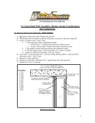
Submittal Detail - <strong>BlazeFrame</strong> "CJB" (Control Joint Backer)<br />
<strong>BlazeFrame</strong> "CJB" (Control Joint Backer<br />
Certified to ASTM E-119 Standards - (WFCi - Report #12033)<br />
Up to 2 Hour Fire Rated Protection<br />
Install Before or After Cavity Obstructions<br />
Eliminate Drywall Rips/Mineral Wool and Extra Stud<br />
Eliminate Fire Caulking of Penetrations through Cavity Drywall Rips<br />
Zinc or Vinyl Architectural Control Joint (optional)<br />
1.00"<br />
Intumescent<br />
Part #<br />
1.25" .75" 1.25"<br />
Intumescent<br />
Width<br />
Profile<br />
Width<br />
Gauge<br />
CJB-18 1.25" 3.25" .018<br />
www.blazeframe.com<br />
33
Project Submittal –<strong>Basic</strong> <strong>Concrete</strong> w/<strong>Poured</strong> <strong>Beams</strong><br />
Installation:<br />
-Locate first flange of CJB between wall "stud" and wall sheathing<br />
-Fasten CJB max. 8" O/C utilizing wall sheathing fasteners for attachment<br />
-Span wall sheathing from adjacent "stud" and attach to second CJB flange<br />
-Edges of wall sheathing align with edges of intumescent material<br />
Rated 1 hour - Top View CJB at Stud/Jamb (Single Side & Back to Back)<br />
Rated 2 Hour - Top View CJB at Stud/Jamb (Single Side & Back to Back)<br />
Profiles are manufactured with 25ga galvanized steel complying with ASTM A653 having a minimum<br />
G40 coating. Profiles comply with ASTM C645 and are installed behind joints in wall sheathing where<br />
control joints (Zinc or Vinyl 093) are installed to prevent face cracking.<br />
www.blazeframe.com<br />
34
Project Submittal –<strong>Basic</strong> <strong>Concrete</strong> w/<strong>Poured</strong> <strong>Beams</strong><br />
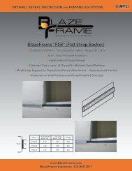
Submittal Detail - <strong>BlazeFrame</strong> "FSB" (Flat Strap Backer)<br />
Certified to ASTM E-119 Standards - (WFCi - Report #12142)<br />
Up to 2 Hour Fire Rated Protection<br />
Install Behind Drywall Reveal Moldings<br />
Eliminate "Extra Layer" of Drywall to Maintain Rated Partition<br />
Metal Strap Support for Drywall and Reveal Attachment - Horizontal and Vertical<br />
Zinc or Vinyl Architectural Reveal Molding Installed Over Gap<br />
Part #<br />
Intumescent<br />
Width "IW"<br />
Flat Strap<br />
Width "FSW"<br />
Gauge<br />
"FSW"<br />
"IW"<br />
FSB075<br />
FSB100<br />
0.75"<br />
1.00"<br />
3.00"<br />
3.00"<br />
.030<br />
.030<br />
FSB125 1.25"<br />
3.00"<br />
.030<br />
www.blazeframe.com<br />
35
Project Submittal –<strong>Basic</strong> <strong>Concrete</strong> w/<strong>Poured</strong> <strong>Beams</strong><br />
Submittal Detail - <strong>BlazeFrame</strong> "FSB" (Flat Strap Backer)<br />
Installation:<br />
-Locate FSB taught between "stud(s)" and wall sheathing<br />
-Edges of wall sheathing align with edges of intumescent material<br />
-Fasten Sheathing Edges max. 8" O/C use sheathing fasteners for attachment<br />
-Install Reveal Moulding over Gap - (1/2" deep profile)<br />
Horizontal - Side View FSB (One and Two Hour)<br />
Vertical - Top View FSB with Stud Backer (One and Two Hour)<br />
FSB Profiles are manufactured with 20ga galvanized steel complying with ASTM A653 having a<br />
minimum G40 coating. Profiles comply with ASTM C645 and are installed behind joints in wall<br />
sheathing where reveal molding (Zinc or Vinyl) are installed.<br />
www.blazeframe.com<br />
36