Sound (STC) Testing Results - BlazeFrame
Sound (STC) Testing Results - BlazeFrame
Sound (STC) Testing Results - BlazeFrame
- No tags were found...

You also want an ePaper? Increase the reach of your titles
YUMPU automatically turns print PDFs into web optimized ePapers that Google loves.
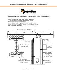
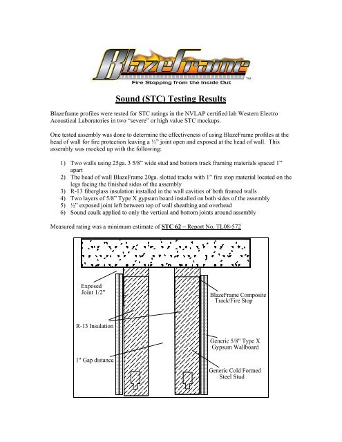
<strong>Sound</strong> (<strong>STC</strong>) <strong>Testing</strong> <strong>Results</strong>Blazeframe profiles were tested for <strong>STC</strong> ratings in the NVLAP certified lab Western ElectroAcoustical Laboratories in two “severe” or high value <strong>STC</strong> mockups.One tested assembly was done to determine the effectiveness of using <strong>BlazeFrame</strong> profiles at thehead of wall for fire protection leaving a ½” joint open and exposed at the head of wall. Thisassembly was mocked up with the following:1) Two walls using 25ga. 3 5/8” wide stud and bottom track framing materials spaced 1”apart2) The head of wall <strong>BlazeFrame</strong> 20ga. slotted tracks with 1” fire stop material located on thelegs facing the finished sides of the assembly3) R-13 fiberglass insulation installed in the wall cavities of both framed walls4) Two layers of 5/8” Type X gypsum board installed on both sides of the assembly5) ½” exposed joint left between top of wall sheathing and overhead6) <strong>Sound</strong> caulk applied to only the vertical and bottom joints around assemblyMeasured rating was a minimum estimate of <strong>STC</strong> 62 – Report No. TL08-572ExposedJoint 1/2"<strong>BlazeFrame</strong> CompositeTrack/Fire StopR-13 InsulationGeneric 5/8" Type XGypsum Wallboard1" Gap distanceGeneric Cold FormedSteel Stud
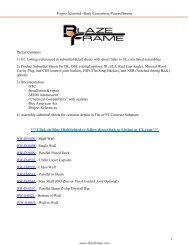
A second tested assembly was measured to determine the effectiveness of using <strong>BlazeFrame</strong> RCTand RCB profiles at the top and bottom respectively of the wall assembly leaving ½” gaps openand exposed at both top and bottom of wall. This assembly was mocked up with the flowing:1) One single wall using 25ga. 3 5/8” wide stud2) Top track was 20ga. <strong>BlazeFrame</strong> RCT profile having slots one side and solid leg/1/2”return on opposing side with 1” fire stop material located on the legs facing the finishedsides of the assembly3) Bottom track was 20ga. <strong>BlazeFrame</strong> RCB profile having 1 ¼” legs and ½” return on oneside with 1” fire stop material located on the legs facing the finished sides of theassembly4) R-13 fiberglass insulation installed in the wall cavity5) Generic resilient channel installed 24” O/C on side of wall with track extended beyondstud having ½” returns6) Two layers of 5/8” Type X gypsum board installed on side of wall opposite the RC-17) One layer of 5/8” Type X gypsum board installed over and attached to the RC17) ½” exposed joint left between top of wall sheathing and overhead8) ½” exposed joint left between bottom of wall sheathing and floor9) <strong>Sound</strong> caulk applied to the vertical joints onlyMeasured rating was <strong>STC</strong> 52 – Report No. TL08-574RCT (Top Track RC-1 Wall)RCB (Bottom Track RC-1 Wall)
Fire Rated Wall Assembly Detail (RC-1 <strong>Sound</strong> Wall)Exposed Joint 1/2"<strong>BlazeFrame</strong> CompositeRCT Track/Fire Stop5/8" Type XGypsum WallboardResilient Channel1/2" distance fromstud to drywallCold FormedSteel StudR-13 FiberglassInsulation<strong>BlazeFrame</strong> CompositeRCB Track/Fire StopExposed Joint 1/2"