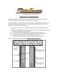
Basic Metal Deck - BlazeFrame
Basic Metal Deck - BlazeFrame
Basic Metal Deck - BlazeFrame
- No tags were found...

You also want an ePaper? Increase the reach of your titles
YUMPU automatically turns print PDFs into web optimized ePapers that Google loves.
<strong>BlazeFrame</strong> Ind.8805 NE 148 th Ave NERedmond, WA425-869-2811www.blazeframe.com
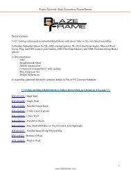
<strong>Basic</strong> Submittal – Bare <strong>Deck</strong>Packet Contains:1. UL Listings referenced in submittal detail sheets with direct links to UL.com listed assemblies2. Product Submittal Sheets for DL, DSL (slotted), ODL, ODSL (slotted), JR, OJR, FC (FluteCover), Mineral Wool Flute/Shaft Cavity, and CJB (control joint backer) options3. Documentation:a. Installation & repairb. MSDS intumescentc. <strong>BlazeFrame</strong> LEED Informationd. Compatibility with Fire Proofinge. "Chemical Compatibility" with sealantsf. Buy American Actg. Project References4. Assembly submittal sheets for common details in Corrugated <strong>Metal</strong> <strong>Deck</strong> (uncoated)/StructuralSteel (Red Iron with fire proofed protection)***Ctrl + Click on Blue Highlighted to follow direct link to Listing at UL.com***HW-D-0495 - Beam PenetrationHW-D-0496 - Shaft WallHW-D-0498 - Standard Wall Flat ConcreteHW-D-0499 - Centered Under Valley ParallelHW-D-0502 - Parallel Edge Overlap Under BeamHW-D-0504 - Shaft Wall Parallel Beam Unprotected <strong>Deck</strong>HW-D-0506 - Under Fluted <strong>Metal</strong> <strong>Deck</strong> (Chase Wall)HW-D-0513 - Perpendicular Unprotected <strong>Deck</strong> w/Stuff and Spray Flute FillHW-D-0543 - Stair Shaft (093 Zinc or Vinyl Control Joint Optional)HW-D-0544 - Parallel under Flute (Flute Cover Plate)HW-D-0588 - Offset Leg through Fire ProofingHW-D-0597 - Parallel Beam Z-clip/drywall ripHW-D-0631 - Shaft Wall Cantilevered Edge of BeamBW-S-0021 - Bottom of WallWW-S-0055 - Vertical Wall to Wall Jointwww.blazeframe.com 1
<strong>Basic</strong> Submittal – Bare <strong>Deck</strong>Product SubmittalPS1 - “DL” (Deep Leg) Profiles with two solid legsComposite Fire Stop/Framing for use in up to 3 hr rated wall assemblies. Provides 100% unencumbered jointprotection accommodates up to 3" overall movement with level III (seismic) certification. Minimum G40 (20ga)and G60 (18ga and heavier) coating with two solid legs supporting “free floating” studs per listed assemblies inUL Fire Resistance Directory.(I)(L)Pat. PendWidths (W) Mil (Ga) Part Identification250 (2 1/2") .030 (20) Example: 400DL2 - 30362 (3 5/8") .033 (20)400 DL400 (4") .043 (18)2 - 30600 (6") .054 (16)800 (8")Track Width Series.068 (14)Profile Gauge1 - Series (Fire Stop One Side)(W)2 - Series (Fire Stop Both Sides)(W)(L) (L) (L) (L)ProfileDLDLWDLXDLZLeg Length(L)2.00"2.00"2.50"3.00"Strip Width(I)1.00"1.25"1.75"2.25"DLY 4.00" 3.25"Slot Height(S)N/AN/AN/AN/AJointProtection.75"1.00"1.50"2.00"N/A 3.00"UL, ASTM & Code StandardsLeed PointsUL2079 & ULC S115-M95MR 2.1 & 2.2 - Construction Waste: up to 2ptsASTM E814, E1966, E2837MR 4.1 & 4.2 - Recycled Content: up to 2 ptsA1003, A653, A924, C645, C754, C955 MR 5.1 & 5.2 - Regional ProximityAISI 2004 NASEQ 4.1 - Low Emitting Materials2009 IBC & 2010 CBC EQ 9 - Enhanced AcousticalPhone: (425) 869-2811 Fax: (425) 869-2300www.blazeframe.com 2
<strong>Basic</strong> Submittal – Bare <strong>Deck</strong>Product SubmittalPS7 - “DSL” (Slotted Both Sides) Profiles with two slotted legsComposite Fire Stop/Framing for use in up to 3 hr rated wall assemblies. Provides 100% unencumbered jointprotection accommodates up to 1 1/2” overall movement with level III (seismic) certification. Minimum G40(20ga) and G60 (18ga and heavier) coating two legs with slots spaced 1” O/C for attachment of studs per listedassemblies in UL Fire Resistance Directory.(I)(S)(L)1.00" .25"Fastener mid-heightof exposed slotWidths (W) Mil (Ga) Part Identification250 (2 1/2") .030 (20) Example: 362DSL2-30362 (3 5/8") .033 (20)400 (4") .043 (18) 362 DSL 2 - 30600 (6") .054 (16)800 (8") .068 (14) Track Width SeriesProfile Gauge1 - Series (Fire Stop One Side) 2 - Series (Fire Stop Both Sides)(W)(W)(L) (L) (L) (L)ProfileDSLDSLWDSLXLeg Length(L)3.00"3.00"4.00"Strip Width(I)1.00"1.25"1.75"Slot Height(S)1.50"1.50"2.00"JointProtection.75"1.00"1.50"UL, ASTM & Code StandardsLeed PointsUL2079 & ULC S115-M95MR 2.1 & 2.2 - Construction Waste: up to 2ptsASTM E814, E1966, E2837MR 4.1 & 4.2 - Recycled Content: up to 2 ptsA1003, A653, A924, C645, C754, C955 MR 5.1 & 5.2 - Regional ProximityAISI 2004 NASEQ 4.1 - Low Emitting Materials2009 IBC & 2010 CBC EQ 9 - Enhanced AcousticalPhone: (425) 869-2811 Fax: (425) 869-2300www.blazeframe.com 3
<strong>Basic</strong> Submittal – Bare <strong>Deck</strong>Product SubmittalPS10 - “ODL” (Offset Deep Leg) Profiles with two offset solid legsComposite Fire Stop/Framing “offset step” accommodates fireproofing in head of wall and wall to wall (column)assemblies. Provides 100% unencumbered joint protection accommodates up to 3” overall movement with levelIII (seismic) certification. Minimum G40 (20ga) and G60 (18ga and heavier) coating with two solid legs per ULlisted assemblies.(D)(I)(L)Widths (W) Mil (Ga)Pat. Pend362 (3 5/8") .030 (20)Part Identification400 (4") .033 (20)600 (6") .043 (18) Example: 362ODL2150-30800 (8") .054 (16)362 ODL 2 150 - 30Depth (D)Track Width SeriesGauge.75"1.25"Profile "Upper leg"Depth1.50"1 - Series "Deep Leg" (Fire Stop One Side) 2 - Series "Deep Leg" (Fire Stop Both Sides)(W)(W)(D).75".75"(L)(D).75".75"(L)Profile Lower Leg Length Strip Width Slot Height Joint(L)(I) (S) ProtectionODLODLWODLXODLZ2.00"2.00"2.50"3.00"1.00"1.25"1.75"2.25"N/AN/AN/AN/A.75"1.00"1.50"2.00"ODLY 3.75"3.25" N/A 3.00"UL, ASTM & Code StandardsLeed PointsUL2079, E814, E1966, ULC S115-M95MR 2.1 & 2.2 - Construction Waste: up to 2ptsASTM E814, E1966MR 4.1 & 4.2 - Recycled Content: up to 2 ptsA1003, A653, A924, C645, C754, C955 MR 5.1 & 5.2 - Regional ProximityAISI 2004 NASEQ 4.1 - Low Emitting Materials2009 IBC & 2010 CBC EQ 9 - Enhanced AcousticalPhone: (425) 869-2811 Fax: (425) 869-2300www.blazeframe.com 4
<strong>Basic</strong> Submittal – Bare <strong>Deck</strong>Product SubmittalPS11 - “ODSL” (Offset Slotted Leg) Profiles with two offset slotted lower legsComposite Fire Stop/Framing with “offset step” accommodates fireproofing in head of wall and wall to wall(column) assemblies. Provides 100% unencumbered joint protection accommodating up to 1 1/2” overallmovement with level III (seismic) UL certification. Minimum G40 (20ga) and G60 (18ga and heavier) coatingtwo legs with slots spaced 1” O/C for permanent attachment of studs per UL listed assemblies.(D)(I)(S)(L)Widths (W)362 (3 5/8")400 (4")600 (6")800 (8")Depth (D).75"1.25"1.50"(D)1.00" .25"Mil (Ga).030 (20).033 (20).043 (18).054 (16).75"Track WidthFastener mid-heightof exposed slotODSL1 - "Slotted Leg" (Fire Stop One Side)(W).75"Pat. PendPart IdentificationExample: 362ODSL2150-30362 ODSL 2 150 - 30ProfileSeries(L)"Upper leg"DepthGaugeODSL2 - "Slotted Leg" (Fire Stop Both Sides)(W)(D).75".75"(L)ProfileODSLODSLWODSLXLower Leg Length(L)3.00"3.00"4.00"Strip Width(I)1.00"1.25"1.75"Slot Height(S)1.50"1.50"2.00"JointProtection.75"1.00"1.50"UL, ASTM & Code StandardsLeed PointsUL2079, E814, E1966, ULC S115-M95MR 2.1 & 2.2 - Construction Waste: up to 2ptsASTM E814, E1966MR 4.1 & 4.2 - Recycled Content: up to 2 ptsA1003, A653, A924, C645, C754, C955 MR 5.1 & 5.2 - Regional ProximityAISI 2004 NASEQ 4.1 - Low Emitting Materials2009 IBC & 2010 CBC EQ 9 - Enhanced AcousticalPhone: (425) 869-2811 Fax: (425) 869-2300www.blazeframe.com 5
<strong>Basic</strong> Submittal – Bare <strong>Deck</strong>Product SubmittalPS27 - <strong>BlazeFrame</strong> “JR” profiles with one short (front) and one long (back) legComposite Fire Stop/Framing for use in up to 3 hr rated shaft wall assemblies. Provides 100% unencumberedjoint protection accommodating up to 1 1/2" overall movement with level III (seismic) certification. MinimumG40 (20ga) and G60 (18ga and heavier) coating with one leg (front) having intumescent per listed assemblies inUL Fire Resistance Directory.(I)(FL)(BL)Pat. PendWidths (W) Gauge250 (2 1/2") .030 (20)400 (4") .033 (20) Part Identification600 (6") .043 (18) Example: 400JR1 - 30.054 (16)400 JR1 - 30Track Width Profile GaugeJR1 - Series (Fire Stop "short leg")(W)(BL)(I) (FL)(FL) (BL)Profile Front Leg Back Leg Strip Width JointJR1JRW1JRX12.00"2.00"2.00"3.00"3.00"3.00"(I)1.00"1.25"1.75"Protection.75"1.00"1.50"UL, ASTM & Code StandardsLeed PointsUL2079 & ULC S115-M95MR 2.1 & 2.2 - Construction Waste: up to 2ptsASTM E814, E1966, E2837MR 4.1 & 4.2 - Recycled Content: up to 2 ptsA1003, A653, A924, C645, C754, C955 MR 5.1 & 5.2 - Regional ProximityAISI 2004 NASEQ 4.1 - Low Emitting Materials2009 IBC & 2010 CBC EQ 9 - Enhanced AcousticalPhone: (425) 869-2811 Fax: (425) 869-2300www.blazeframe.com 6
<strong>Basic</strong> Submittal – Bare <strong>Deck</strong>Product SubmittalPS12 - “OJR” (Offset J-Runner) with one 2” and one 3” solid legsComposite Fire Stop/Framing with “offset step” accommodates fireproofing in shaft wall assemblies. Provides100% unencumbered joint protection accommodating up to 1 1/2” overall movement with level III (seismic)certification. Minimum G40 (20ga) and G60 (18ga and heavier) coating with one 2” and one 3” solid lower legsper listed assemblies in UL Fire Resistance Directory.(D)(FL)(BL)Widths (W)400 (4")600 (6")Depth (D).75"1.25"1.50"Mil (Ga).030 (20).033 (20).043 (18).054 (16)Pat. Pend"D"(I)OJR - "J-Runner" (Fire Stop Short Leg)(W).75".75"(BL)Part IdentificationExample: 400OJR150-30400 OJR 150 - 30ProfileGaugeTrack Width "Upper leg"DepthProfileOJROJRWOJRXFront Leg Back Leg(FL) (BL)2.00" 3.00"2.00" 3.00"2.00" 3.00"Strip Width Joint(I) Protection1.00" .75"1.25" 1.00"1.75" 1.50"UL, ASTM & Code StandardsLeed PointsUL2079, E814, E1966, ULC S115-M95MR 2.1 & 2.2 - Construction Waste: up to 2ptsASTM E814, E1966MR 4.1 & 4.2 - Recycled Content: up to 2 ptsA1003, A653, A924, C645, C754, C955 MR 5.1 & 5.2 - Regional ProximityAISI 2004 NASEQ 4.1 - Low Emitting Materials2009 IBC & 2010 CBC EQ 9 - Enhanced AcousticalPhone: (425) 869-2811 Fax: (425) 869-2300www.blazeframe.com 7
<strong>Basic</strong> Submittal – Bare <strong>Deck</strong>Product SubmittalPS15 - “FC” (Flute Cover) profilesCorrugated Strap for horizontal use to span fluted areas of unprotected or protected metal decks in up to 2 hr ratedassemblies. Profile attached to deck “valley” surfaces a max 16” O/C on both sides. Profile sections arefabricated from hot-dipped galvanized steel complying with ASTM A653 with a minimum G40 (20ga) and G60(18ga and heavier) coating. Profiles comply with ASTM C645 and provide a surface area for attachment of headof wall partition track profiles centered or offset underneath and parallel to deck fluted areas..563"Width Varies to MatchFlute Opening(W)1.5" .875" .875" 1.5"Widths (W)350 (3 1/2")550 (5 1/2")750 (7 1/2")950 (9 1/2")Gauge.030 (20)Part IdentificationExample: FC750 - 30FC 750 - 30ProfileFluteOpeningGaugeUL, ASTM & Code StandardsLeed PointsUL2079 & ULC S115-M95MR 2.1 & 2.2 - Construction Waste: up to 2ptsASTM E814, E1966, E2837MR 4.1 & 4.2 - Recycled Content: up to 2 ptsA1003, A653, A924, C645, C754, C955 MR 5.1 & 5.2 - Regional ProximityAISI 2004 NASEQ 4.1 - Low Emitting Materials2009 IBC & 2010 CBC EQ 9 - Enhanced AcousticalPhone: (425) 869-2811 Fax: (425) 869-2300www.blazeframe.com 8
<strong>Basic</strong> Submittal – Bare <strong>Deck</strong>Product SubmittalPS34 - <strong>Deck</strong> Plugs – Preformed Mineral WoolMineral Wool preformed to contour of metal deck profiles with a 7.0 lbs/ft3 density. Profiles are used to fill andprotect fluted areas above wall partitions.Preformed Mineral Wool Plugs1 1/2" <strong>Deck</strong> DepthDP-245554.50"3" <strong>Deck</strong> DepthDP-4686.00"2.00"5.50"4.00"8.00"2" <strong>Deck</strong> DepthDP-3686.00"3" <strong>Deck</strong> DepthDP-4787.00"3.00"4.00"8.00" 8.00"Phone: (425) 869-2811 Fax: (425) 869-2300www.blazeframe.com 9
<strong>Basic</strong> Submittal – Bare <strong>Deck</strong>Product SubmittalPS37 - Shaft Wall Cavity Plugs – Preformed Mineral WoolMineral Wool preformed to wall cavity widths for protection of joints with a 4.0 lbs/ft3 density. Profiles are usedto fill and protect joints occurring in shaft wall cavities.Stock Lengths: 24"Box Qty: SWCP-250 - 72ea. - (144 lft)SWCP-400 - 39ea. - (78 lft)SWCP-600 - 24 ea. - (48 lft)SWCP-400SWCP-6003.50" 5.50"SWCP-2503.50"4.00"4.00"2.00"Phone: (425) 869-2811 Fax: (425) 869-2300www.blazeframe.com 10
<strong>Basic</strong> Submittal – Bare <strong>Deck</strong>Product SubmittalPS44 - “CJB” profiles for Protection of Control JointsComposite Fire Stop/Control Joint Backer Profiles for use to protect Architectural design joints (optional controljoint over gap) for up to 2 hr rated assemblies. Profile sections are fabricated from hot-dipped galvanized steelcomplying with ASTM A653 with a minimum G40 (25ga). Profiles comply with ASTM C645 and provide ametal profile which support intumescent materials located inside and spanning gap between opposing drywalledges at control joint locations.1.00"1.25" .75" 1.25"IntumescentIntumescent ProfilePart #GaugeWidth WidthCJB-18 1.25" 3.25" .018UL, ASTM & Code StandardsLeed PointsUL263, E814,MR 2.1 & 2.2 - Construction Waste: up to 2ptsA1003, A653, A924, C645, C754, C955 MR 4.1 & 4.2 - Recycled Content: up to 2 ptsAISI 2004 NASMR 5.1 & 5.2 - Regional Proximity2006 & 2009 IBC EQ 4.1 - Low Emitting Materials2010 CBC EQ 9 - Enhanced AcousticalPhone: (425) 869-2811 Fax: (425) 869-2300www.blazeframe.com 11
<strong>Basic</strong> Submittal – Bare <strong>Deck</strong>Installation/Training, Recommendations, and RepairInstallation/Training1) Select and install profile to accommodate overall movement and wall framing requirements2) Attach with approved power actuated or mechanical fasteners per Engineer of Record3) Profiles (intersecting or aligned) in continuous contact with one another4) Overlap intumescent with sheathing per UL Listings or <strong>BlazeFrame</strong> "constructability" designs5) "Chase wall" conditions, locate intumescent in direction of "finished" side of wall6) Training provided to installer of Blaze Frame product, a onsite review with installers will beconducted by <strong>BlazeFrame</strong> prior to installationRecommendations1) Store <strong>BlazeFrame</strong> products in dry covered area2) Avoid exposure to excessive heat3) Install according to UL Listed Assemblies or <strong>BlazeFrame</strong> Constructability designs4) Compatible with non-solvent based products (caulks, paints, coatings, fire proofing, drywall"mud")5) Provide protection of areas adjacent to Blazeframe profile using UL classified applications6) Penetrations through <strong>BlazeFrame</strong> intumescent must be sealed per UL:- "non-solvent" mastic materials/caulks may be overlapped onto <strong>BlazeFrame</strong> intumescent7) Voids adjacent intumescent (deck surface, seams, or embossments and <strong>BlazeFrame</strong>) may besealed with a sliver of mineral wool or mastic/caulks per UL to maintain listed L-ratings:- gaps up to 1/4" (alternate to sliver of mineral wool) mastic/caulks to fill entire gap andmay be overlapped onto <strong>BlazeFrame</strong> intumescent- gaps greater than 1/4" insert min. 4 pcf mineral wool compressed 33% into and fill voidRepair and Installation Gaps1) Bare locations on metal profiles where intumescent damaged/torn off:-clean metal profile "squaring" edges of opposing remaining intumescent-field apply to match strip width (intumescent provided by <strong>BlazeFrame</strong>)-apply intumescent covering all surfaces between opposing "squared" edges2) Gaps 1/8" or smaller between profiles:-apply UL certified caulk filling gap between opposing edges of intumescent-alternate: cover gap overlapping both sides min. 1/2" (intumescent by <strong>BlazeFrame</strong>)3) Gaps up to 1/4" or smaller between profiles:-cover gap overlapping both sides min. 1/2" (intumescent by <strong>BlazeFrame</strong>)4) Gaps wider than 1/4":-install patch per <strong>BlazeFrame</strong> document AC20, AC13, or AC14www.blazeframe.com 12
<strong>Basic</strong> Submittal – Bare <strong>Deck</strong>1. Product DescriptionA strip of highly intumescentfire stop material affixed to metal profilesWhen exposed to heat, this productexpands and forms a hard char to sealoff joint (gap) preventing passage of flames,temperature pass through, and hot gases.2. Material PropertiesAsbestos Fillers: NoneSolvents: NoneHazardous Ingredients: NoneThickness: 2 mmWidth: Per <strong>BlazeFrame</strong> ProfileActivation of Intumescence:3. Testing DataIt has been tested as a dynamic and staticjoint protection fire stop sealant to ASTM E-814, UL 1479, and UL 2079. Complies toRequired Environmental Exposure Testingof Accelerated Aging and High Humidity asper UL 1479 Fire Test of Through-Penetration Firestops.Degree of intumescence per DIN standard≥18x with weight imposed≥ 37x free intumescingASTM E 84, UL 723 Tunnel TestFlame Spread 5Smoke Index 5Expansion Begins 375 ˚F (190˚C)Expansion Greatest 575 ˚ (302˚ C)to 1100˚ F (593˚ C)Color: BlackExposed Surface: Poly CoatingFreeze-Thaw: Excellentwww.blazeframe.com 13
<strong>Basic</strong> Submittal – Bare <strong>Deck</strong>LEED (Leadership in Energy and Environmental Design)The following information is provided to assist Architects and Persons responsible for obtaining a U.S.Green Building Council (USGBC) Certification.<strong>BlazeFrame</strong> composite steel/intumescent profiles are manufactured in Auburn, WA and consist of a ratioof steel to intumescent (by weight) of approximately 90% and 10% respectively. Our product profilesqualify for the following credit requirements:Steel:Credit MR 2.1 & 2.2 - Construction Waste Management: up to 2 pointsCredit MR 4.1/4.2 – Recycled Content RequirementsSteel used in the manufacture of our steel profiles contains approximately 32.3% recycled steelconsisting of 25.5% Post-Consumer and 6.8% Pre-Consumer.Credit MR 5.1/5.2 – Regional Materials Requirements (Applies for some projects)Steel used in the manufacture of our steel profiles is purchased from sources within 500 miles of ourmanufacturing facility (Auburn, WA). Steel may contain local materials and recycled content, not all ofthe steel content generally comes from local sources.Intumescent:Credit EQ 4.1 – Low Emitting Materials: Adhesives & SealantsCured intumescent and adhesives used in the manufacture of our profiles contain less than 10 g/l volatileorganic compounds (VOC) and comply with limits established by the South Coast Air QualityManagement District (SCAMQD) Rule #1168, and the Bay Area Air Quality Management DistrictRegulation 8, Rule 51.Credit EQ 9 – Enhanced AcousticalWhy is there no LEED Certification on the product label?According to USGBC: “USGBC certifies buildings, not the materials that are used to construct thebuildings. Only USGBC can use the LEED logo. All others violate USGBC’s registered trademarkrights.”www.blazeframe.com 14
<strong>Basic</strong> Submittal – Bare <strong>Deck</strong>AC25 - Compatibility with Fire Proofing Materials<strong>BlazeFrame</strong> profiles are third party certified and listed by Underwriter's Laboratory to becompatible with fire-proofed substrates listed in UL Fire Resistance Directory.Application requirements of fire proofing materials (covered by individual assemblylistings), Manufacturer, and brand names of fire proofing materials can be found in D700/D900, P700/P900, and P800 series assemblies.(Example) - UL Listing D902 certification includes:ISOLATEK INTERNATIONAL — Type D-C/F, HP, Type II, Type EBS or TypeISOLATEK INTERNATIONAL — Type 280.ISOLATEK INTERNATIONAL — Types 800, M-II or TG. Types 800, M-II and TGInvestigated for exterior use.NEWKEM PRODUCTS CORP — Types M-II or TG. Types M-II and TG Investigatedfor exterior use.LUCKY CORE INSULATING MATERIAL MANUFACTURING L L C — TypesM-II or TG. Types M-II and TG Investigated for exterior use.BERLIN CO LTD — Types 300, 300ES, 300N or SB.ISOLATEK INTERNATIONAL — Type 300, Type 300ES, Type 300N, or Type SB.NEWKEM PRODUCTS CORP — Type 300, Type 300ES, Type 300N, or Type SB.ISOLATEK INTERNATIONAL — Type 300TW, Type 400.NEWKEM PRODUCTS CORP — Type 400.Etc...(Example) - UL listing D905 certification includes:ARABIAN VERMICULITE INDUSTRIES — Type MK-5.GRACE KOREA INC — Types MK-6/CBF, MK-6/ED, MK-6/HY, MK-6s, MonokoteAcoustic 1 .PYROK INC — Type LD.SOUTHWEST FIREPROOFING PRODUCTS CO — Types 4, 5, 5EF, 5GP, 5MD,7GP, 7HD, 8EF, 8GP, 8MD, 9EF, 9GP, 9MD.W R GRACE & CO - CONN — Types MK-4, MK-5, MK-6/HY, MK-6s, MonokoteAcoustic 1 , RG .Installation and use of <strong>BlazeFrame</strong> profiles in assemblies having a fire-proofed substrateare specified in individual HW-D listings. Directory of <strong>BlazeFrame</strong> UL listings withdirect link to UL listings at www.ul.com are available at www.blazeframe.comwww.blazeframe.com 15
<strong>Basic</strong> Submittal – Bare <strong>Deck</strong>AC27 - Chemical Compatibility with Sealants<strong>BlazeFrame</strong> steel/intumescent composite joint framing/protection profiles are producedusing a cured intumescent acting as the "fill, void, cavity" materials with a polyester outercoating. The intumescent portion of the composite profile is chemically compatible with"non-solvent" based materials (i.e. caulks, mud, paints, fire proofing, etc..) and as suchwill be unaffected and not degrade where contact may occur.Current sealant manufacturer's products verified as non-solvent and compatible with<strong>BlazeFrame</strong> profiles are:Rectorseal:Metacaulk - 1000, 350i, MC 150+, 950, 1100, 1200, 1500Biostop - 500+, 350i, BF 150+, 700, 750, 800Flamesafe - FS1900, FS 900+, FS3000United States Gypsum (USG):Type ASOther brand names may be acceptable based on individual manufacturer of specific brandproviding verification of materials being "non-solvent" and will allow/warranty use ofthem in applicable conditions.www.blazeframe.com 16
<strong>Basic</strong> Submittal – Bare <strong>Deck</strong>AC26 - Buy American Act Certification<strong>BlazeFrame</strong> steel/intumescent composite joint framing/protection profiles are produced inUSA at manufacturing facility located in Auburn WA. and consist of two parts:Steel (approx. 95% weight of composite profiles) having min 32% recycle content andsourced 100% from combination of following US mills:-USS-Posco Industries - Pittsburg, CA-SteelScape - Kalama, WA or Rancho Cucamonga, CA-California Steel Industries (CSI) - Fontana, CAIntumescent (approx 5% weight of composite profiles) joint protection material is 100%manufactured in Houston, TXAll <strong>BlazeFrame</strong> composite forming and assembly occurs at facility located in Auburn,WA. Materials are shipped from WA to individual project locations.Additional information covering <strong>BlazeFrame</strong> Industries and all product, certification, andrelated information can be accessed at www.blazeframe.com.www.blazeframe.com 17
<strong>Basic</strong> Submittal – Bare <strong>Deck</strong>Projects to use <strong>BlazeFrame</strong> Products - West CoastProject: 7th & Fig Mall Renovation - (Los Angeles, CA)Owner: Brookfield PropertiesArchitect: GenslerGC/Contractor: Turner Construction - Standard DrywallProject: Camp Pendleton Navy Hospital - (San Diego, CA)Owner: US Marine Corp - Camp PendletonArchitect: HKSGC/Contractor: Clark/McCarthy - Component WestProject: Torrance Memorial Center New Tower - (Los Angeles, CA)Owner: Torrance Memorial Medical CenterArchitect: HMC ArchitectsGC/Contractor: McCarthy Building Cos. Inc - Capparelli/KHS&SProject: 2201 Westlake - (16 story condo tower) - (Seattle, WA)Owner: Vulcan Real EstateArchitect: CallisonContractor: Expert DrywallProject: Hyatt Regency - (20 story hotel addition) - (Bellevue, WA)Owner: Kemper DevelopmentArchitect: Sclater PartnersContractor: Anning JohnsonProject: Camp Withycombe Armory - (Clackamas, OR)Owner: Oregon Military Dept.Architect: R.F. StearnsGC/Contractor: Hoffman - Western Partitions IncProject: Amazon.com Headquarters (5 story blocks & 2 -12 story towers) - (Seattle,WA)Owner: Vulcan Real EstateArchitect: CallisonContractor: Expert Drywall & Anning JohnsonProject: Oregon State Hospital (Replacement Remodel and Addition) - (Salem, OR)Owner: State of OregonArchitect: KMD ArchitectsContractor: Performance Contracting Inc. (PCI)www.blazeframe.com 18
<strong>Basic</strong> Submittal – Bare <strong>Deck</strong>Projects to use <strong>BlazeFrame</strong> Products - East CoastProject: St Joseph's Regional Medical/ Children's Addition - (Paterson, NJ)Owner: St Joseph'sArchitect: Francis Cauffman ArchitectsGC/Contractor: Sterling Barnett Little Inc - Sloan and CompanyProject: Credit Suisse Data Center - (Clifton, NJ)Owner: Russo DevelopmentArchitect: RussoContractor: Component AssemblyProject: The Green at Florham Park - (Florham Park, NJ)Owner: The Rockefeller GroupArchitect: KPF ArchitectsContractor: Sloan and CompanyProject: International Gem Tower - (New York, NY)Owner: Extell Development CoArchitect: Skidmore, Owings & Merrill, LLPGC/Contractor: Tishman Construction Corp. - Pabco ConstructionProject: Mercer County Courthouse - (Trenton, NJ)Owner: Mercer CountyArchitect: VitettaGC/Contractor: Ernest Bock & Sons - Sloan and CompanyProject: Novartis Pharmaceuticals - (East Hanover, New Jersey)Owner: Novartis PharmaceuticalsArchitect: GenslerContractor: BJMProject: JFK Airport Expansion - (New York, NY)Owner: Port Authority of New YorkArchitect: GenslerGC/Contractor: Component Assembly SystemsProject: Campus Center SUNY Farmingdale State College - (Farmingdale, NY)Owner: SUNY Farmingdale State CollegeArchitect: Kevin Hom & Andrew Goldman ArchitectsContractor: Kokolakis Construction - Pabco Constructionwww.blazeframe.com 19
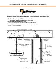
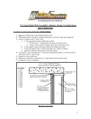
<strong>Basic</strong> Submittal – Bare <strong>Deck</strong>Submittal Detail - Perpendicular to Flute & Parallel Next to Coated BeamUD1 - Perpendicular Flute Parallel next to Structural SupportJoint Movement Capabilities (MC) / Profile Series refer to UL Listing: HW-D-0513¾” MC - (Stock Series) 1” MC - ("W" Series) 1 1/2” MC - ("X" Series)2” MC - ("Z" Series) 3" MC - ("Y" Series)Fastener Attachment 24" O/C max.Installed Gap(See Notes)Mineral WoolFlute Fill<strong>BlazeFrame</strong> CompositeTrack/Fire Stop1" to 4"(See Notes)5/8" Type XGypsum Wallboard1, 2, 3 Layersfor 1, 2, 3 Hr Rating(When Exists)Fastener below ObstructionMax 24" from O/HSteel StudMax 24" O/C1. Installed Gap (compression only) = movement capability (MC) of profile2. Installed Gap (compress + extension) = ½ movement capability (MC) of profile3. Attach to substrate with approved fastener max 24” O.C or per E.O.R.4. Do not screw drywall or stud to <strong>BlazeFrame</strong> solid leg profile studs "free float"5. “Slotted” profile metal framing fastener installed center of slot (min. one side)6. Drywall fasteners 1” to 4" below <strong>BlazeFrame</strong> to accommodate MC or at bottom of obstruction7. 1, 2, or 3 hr rating layers of 5/8” refer to UL U400 or V400 series designsUL, ASTM & Code StandardsLeed PointsUL2079 & ULC S115-M95MR 2.1 & 2.2 - Construction Waste: up to 2ptsASTM E814, E1966, E2837MR 4.1 & 4.2 - Recycled Content: up to 2 ptsA1003, A653, A924, C645, C754, C955 MR 5.1 & 5.2 - Regional ProximityAISI 2004 NASEQ 4.1 - Low Emitting Materials2009 IBC & 2010 CBC EQ 9 - Enhanced AcousticalPhone: (425) 869-2811 Fax: (425) 869-2300www.blazeframe.com 20
<strong>Basic</strong> Submittal – Bare <strong>Deck</strong>Submittal Detail - Parallel Next to Coated Beam Z-Clip & DrywallSS23 - Full Height Wall Parallel to Beam (Inside Angle/Drywall Rip)Joint Movement Capabilities (MC) / Profile Series refer to UL Listing: HW-D-0597¾” MC - (Stock Series) 1” MC - ("W" Series) 1 1/2” MC - ("X" Series)2” MC - ("Z" Series) 3" MC - ("Y" Series)Fastener Attachment 24" O/C max.Mineral WoolFastener Attachment intoZ-Clip Outrigger 16" O/C<strong>BlazeFrame</strong> CompositeTrack/Fire StopZ-Clip Outrigger(16" O/C)Installed Gap(See Notes)1" to 4"(See Notes)5/8" Type XGypsum Wallboard<strong>BlazeFrame</strong> CompositeAngle/Fire Stop"ISA" ProfileSteel StudMax 24" O/C1. Installed Gap (compression only) = movement capability (MC) of profile2. Installed Gap (compress + extension) = ½ movement capability (MC) of profile3. Z-clip outrigger max 16” O/C with approved fasteners or per E.O.R.4. Do not screw drywall or stud to <strong>BlazeFrame</strong> solid leg profile studs "free float"5. “Slotted” profile metal framing fastener installed center of slot6. Drywall fasteners 1" to 4" below <strong>BlazeFrame</strong> to accommodate MCUL, ASTM & Code StandardsLeed PointsUL2079 & ULC S115-M95MR 2.1 & 2.2 - Construction Waste: up to 2ptsASTM E814, E1966, E2837MR 4.1 & 4.2 - Recycled Content: up to 2 ptsA1003, A653, A924, C645, C754, C955 MR 5.1 & 5.2 - Regional ProximityAISI 2004 NASEQ 4.1 - Low Emitting Materials2009 IBC & 2010 CBC EQ 9 - Enhanced AcousticalPhone: (425) 869-2811 Fax: (425) 869-2300www.blazeframe.com 21
<strong>Basic</strong> Submittal – Bare <strong>Deck</strong>Submittal Detail - Parallel to Beam Cantilevered Edge Offset Leg ProfileSS28 - Edge of Structural Support with Angle (Offset Leg Profile)Joint Movement Capabilities (MC) / Profile Series design refer to UL Listing: HW-D-0502¾” MC - (Stock Series) 1” MC - ("W" Series) 1 1/2” MC - ("X" Series)2” MC - ("Z" Series) 3" MC - ("Y" Series)<strong>Metal</strong> Pan <strong>Deck</strong>Fire Proofing(Thickness by Others)Structural SteelSupportMin. 14ga strap/anglefastened to web andopposing offset legFastener Attachment16" O/C max.Installed Gap(See Notes)<strong>BlazeFrame</strong> CompositeTrack/Fire Stop"OL" - Series1" to 4"(See Notes)5/8" Type XGypsum WallboardSteel StudMax 24" O/C1. Installed Gap (compression only) = movement capability (MC) of profile2. Installed Gap (compress + extension) = ½ movement capability (MC) of profile3. Attach Strap/Angle with approved fastener max 16” O.C or per E.O.R.4. Do not screw drywall or stud to <strong>BlazeFrame</strong> solid leg profile studs "free float"5. “Slotted” profile metal framing fastener installed center of slot (min. one side)6. Drywall fasteners 1” to 4" below <strong>BlazeFrame</strong> to accommodate MCUL, ASTM & Code StandardsLeed PointsUL2079, & ULC S115-M95MR 2.1 & 2.2 - Construction Waste: up to 2ptsASTM E814, E1966MR 4.1 & 4.2 - Recycled Content: up to 2 ptsA1003, A653, A924, C645, C754, C955 MR 5.1 & 5.2 - Regional ProximityAISI 2004 NASEQ 4.1 - Low Emitting Materials2009 IBC & 2010 CBC EQ 9 - Enhanced AcousticalPhone: (425) 869-2811 Fax: (425) 869-2300www.blazeframe.com 22
<strong>Basic</strong> Submittal – Bare <strong>Deck</strong>Submittal Detail - Shaft Wall Parallel to BeamSS6 - Shaft Wall Parallel to Structural SupportJoint Movement Capabilities (MC) / Profile Series refer to UL Listing:¾” MC - (Stock Series) 1” MC - ("W" Series)HW-D-05041 ½” MC - ("X" Series) 2” MC - ("Z" Series)Fastener Attachment 24" O/C max.Mineral Wool orFire ProofingInstalled Gap(See Notes)<strong>BlazeFrame</strong> CompositeTrack/fire Stop4 pcf Mineral Woolcompressed 33%1" Shaft(When Exists)Liner BoardFastener below ObstructionMax 24" from O/HCT, CH, or IShaft Stud5/8 Type X Max 24" O/CGypsum Wallboard1. Installed Gap (compression only) = movement capability (MC) of profile2. Installed Gap (compress + extension) = ½ movement capability (MC) of profile3. Attach to substrate with approved fastener max 24” O.C or per E.O.R.4. Do not screw drywall or stud to <strong>BlazeFrame</strong> solid leg profile studs "free float"5. “Slotted” profile metal framing fastener installed center of slot (if possible)6. Drywall fasteners at bottom of beam obstruction or max. 24" from substrateUL, ASTM & Code StandardsLeed PointsUL2079, & ULC S115-M95MR 2.1 & 2.2 - Construction Waste: up to 2ptsASTM E814, E1966MR 4.1 & 4.2 - Recycled Content: up to 2 ptsA1003, A653, A924, C645, C754, C955 MR 5.1 & 5.2 - Regional ProximityAISI 2004 NASEQ 4.1 - Low Emitting Materials2009 IBC & 2010 CBC EQ 9 - Enhanced AcousticalPhone: (425) 869-2811 Fax: (425) 869-2300www.blazeframe.com 23
<strong>Basic</strong> Submittal – Bare <strong>Deck</strong>Submittal Detail - Shaft Parallel Next to Coated Beam Z-Clip & DrywallUD26 - Shaft Wall Perpendicular Z-Clip and Drywall RipJoint Movement Capabilities (MC) / Profile Series refer to UL Listing: HW-D-0597 & 0504¾” MC - (Stock Series) 1” MC - ("W" Series)1 ½” MC - ("X" Series) 2” MC - ("Z" Series)Fastener Attachment 24" O/C max.Mineral WoolFastener Attachment intoZ-Clip Outrigger 16" O/C<strong>BlazeFrame</strong> CompositeTrack/Fire StopZ-Clip Outrigger(16" O/C)Installed Gap(See Notes)1" to 4"(See Notes)5/8" Type XGypsum Wallboard<strong>BlazeFrame</strong> CompositeAngle/Fire Stop"ISA" ProfileSteel StudMax 24" O/C1. Installed Gap (compression only) = movement capability (MC) of profile2. Installed Gap (compress + extension) = ½ movement capability (MC) of profile3. Attach to substrate with approved fastener max 24” O.C or per E.O.R.4. Do not screw drywall or stud to <strong>BlazeFrame</strong> solid leg profile studs "free float"5. “Slotted” profile metal framing fastener installed center of slot (finished side)6. Drywall fasteners 1” to 4" below <strong>BlazeFrame</strong> to accommodate MC or at bottom of obstructionUL, ASTM & Code StandardsLeed PointsUL2079 & ULC S115-M95MR 2.1 & 2.2 - Construction Waste: up to 2ptsASTM E814, E1966, E2837MR 4.1 & 4.2 - Recycled Content: up to 2 ptsA1003, A653, A924, C645, C754, C955 MR 5.1 & 5.2 - Regional ProximityAISI 2004 NASEQ 4.1 - Low Emitting Materials2009 IBC & 2010 CBC EQ 9 - Enhanced AcousticalPhone: (425) 869-2811 Fax: (425) 869-2300www.blazeframe.com 24
<strong>Basic</strong> Submittal – Bare <strong>Deck</strong>Submittal Detail - Shaft Wall Parallel to Beam Cantilevered Edge Offset Leg ProfileSS29 - Edge of Structural Support with Angle (Offset Leg Shaft Profile)Joint Movement Capabilities (MC) / Profile Series design refer to UL Listing:¾” MC - (Stock Series) 1” MC - ("W" Series)HW-D-06311 ½” MC - ("X" Series) 2” MC - ("Z" Series)<strong>Metal</strong> Pan <strong>Deck</strong>Fire Proofing(Thickness by Others)Structural SteelSupportMin. 16ga anglefastened to web andupper legFastener Attachment24" O/C max.Installed Gap(See Notes)1" to 4"(See Notes)<strong>BlazeFrame</strong> CompositeTrack/Fire Stop"OL" - SeriesMin. 4pcf mineral woolCT, CH, or I-Stud5/8" Type X Max 24" O/CGypsum Wallboard1. Installed Gap (compression only) = movement capability (MC) of profile2. Installed Gap (compress + extension) = ½ movement capability (MC) of profile3. Angle to substrate and offset leg profile with approved fastener max 24” O.C or per E.O.R.4. Do not screw drywall or stud to <strong>BlazeFrame</strong> solid leg profile studs "free float"5. “Slotted” profile metal framing fastener installed center of slot (finished side)6. Drywall fasteners 1” to 4" below <strong>BlazeFrame</strong> to accommodate MCUL, ASTM & Code StandardsLeed PointsUL2079, & ULC S115-M95MR 2.1 & 2.2 - Construction Waste: up to 2ptsASTM E814, E1966MR 4.1 & 4.2 - Recycled Content: up to 2 ptsA1003, A653, A924, C645, C754, C955 MR 5.1 & 5.2 - Regional ProximityAISI 2004 NASEQ 4.1 - Low Emitting Materials2009 IBC & 2010 CBC EQ 9 - Enhanced AcousticalPhone: (425) 869-2811 Fax: (425) 869-2300www.blazeframe.com 25
<strong>Basic</strong> Submittal – Bare <strong>Deck</strong>Submittal Detail - Stair shaft Control Joint Offset Leg ProfileSS5 – By Pass Beam Edge (Offset Leg Profiles)Joint Movement Capabilities (MC) / Profile Series design based on UL: HW-D-502 & 0543¾” MC - (Stock Series) 1” MC - ("W" Series) 1 1/2” MC - ("X" Series)2” MC - ("Z" Series) 3" MC - ("Y" Series)Fire Proofing(Thickness by Others)25ga Hat Channel16" O.C. to SupportDrywall Spans Over 16"Fastener Attachment24" O/C max.Installed Gap(See Notes)1" to 4"(See Notes)5/8" Type XGypsum WallboardControl Joint(Optional)<strong>BlazeFrame</strong> CompositeTrack/Fire Stop"OL" SeriesSteel StudMax 24" O/C1. Installed Gap (compression only) = movement capability (MC) of profile2. Installed Gap (compress + extension) = ½ movement capability (MC) of profile3. Attach to substrate with approved fastener max 24” O.C or per E.O.R.4. Do not screw drywall or stud to <strong>BlazeFrame</strong> solid leg profile studs "free float"5. “Slotted” profile metal framing fastener installed center of slot (min. one side)6. Drywall fasteners 1” to 4" below <strong>BlazeFrame</strong> to accommodate MCUL, ASTM & Code StandardsLeed PointsUL2079, & ULC S115-M95MR 2.1 & 2.2 - Construction Waste: up to 2ptsASTM E814, E1966MR 4.1 & 4.2 - Recycled Content: up to 2 ptsA1003, A653, A924, C645, C754, C955 MR 5.1 & 5.2 - Regional ProximityAISI 2004 NASEQ 4.1 - Low Emitting Materials2009 IBC & 2010 CBC EQ 9 - Enhanced AcousticalPhone: (425) 869-2811 Fax: (425) 869-2300www.blazeframe.com 26
<strong>Basic</strong> Submittal – Bare <strong>Deck</strong>Submittal Detail - Beam PenetrationSS1 - Beam PenetrationJoint Movement Capabilities (MC) / Profile Series refer to UL Listing: HW-D-0495¾” MC - (Stock Series) 1” MC - ("W" Series) 1 1/2” MC - ("X" Series)2” MC - ("Z" Series) 3" MC - ("Y" Series)<strong>Metal</strong> Pan <strong>Deck</strong>Angle or Z-clipattached to beam orSteel Track Frame<strong>BlazeFrame</strong>CompositeTrack/Fire StopFire Proofing orMineral Wool onlyencompass angle or z-clipSteel StudMax 24" O/C5/8 Type XGypsum Wallboard1. Installed Gap (compression only) = movement capability (MC) of profile2. Installed Gap (compress + extension) = ½ movement capability (MC) of profile3. Attach to substrate with approved fastener max 24” O.C or per E.O.R.4. Do not screw drywall or stud to <strong>BlazeFrame</strong> solid leg profile studs "free float"5. “Slotted” profile metal framing fastener installed center of slot (min. one side)6. Drywall fasteners 1” to 4" below <strong>BlazeFrame</strong> to accommodate MCUL, ASTM & Code StandardsLeed PointsUL2079 & ULC S115-M95MR 2.1 & 2.2 - Construction Waste: up to 2ptsASTM E814, E1966, E2837MR 4.1 & 4.2 - Recycled Content: up to 2 ptsA1003, A653, A924, C645, C754, C955 MR 5.1 & 5.2 - Regional ProximityAISI 2004 NASEQ 4.1 - Low Emitting Materials2009 IBC & 2010 CBC EQ 9 - Enhanced AcousticalPhone: (425) 869-2811 Fax: (425) 869-2300www.blazeframe.com 27
<strong>Basic</strong> Submittal – Bare <strong>Deck</strong>Submittal Detail - Parallel Centered Under <strong>Deck</strong> "Flute"UD6 - Centered Under Flute Unprotected <strong>Deck</strong> “FC” (Flute Cover)Joint Movement Capabilities (MC) / Profile Series refer to UL Listing: HW-D-0544¾” MC - (Stock Series) 1” MC - ("W" Series) 1 1/2” MC - ("X" Series)2” MC - ("Z" Series) 3" MC - ("Y" Series)Fastener Attachment 16" O/C max.Fastener Attachment 24" O/C max.Installed Gap(See Notes)<strong>BlazeFrame</strong> CompositeTrack/Fire Stop<strong>BlazeFrame</strong> (FC)Flute Cover(Continuous)1" to 4"(See Notes)5/8 Type XGypsum WallboardSteel StudMax 24" O/C1. Installed Gap (compression only) = movement capability (MC) of profile2. Installed Gap (compress + extension) = ½ movement capability (MC) of profile3. Attach to substrate with approved fastener max 24” O.C or per E.O.R.4. Do not screw drywall or stud to <strong>BlazeFrame</strong> solid leg profile studs "free float"5. “Slotted” profile metal framing fastener installed center of slot (min. one side)6. Drywall fasteners 1” to 4" below <strong>BlazeFrame</strong> to accommodate MC7. Install min 3" width 4pcf mineral wool comp. 33% to fill above flute cover when "open" end(s)UL, ASTM & Code StandardsLeed PointsUL2079 & ULC S115-M95MR 2.1 & 2.2 - Construction Waste: up to 2ptsASTM E814, E1966, E2837MR 4.1 & 4.2 - Recycled Content: up to 2 ptsA1003, A653, A924, C645, C754, C955 MR 5.1 & 5.2 - Regional ProximityAISI 2004 NASEQ 4.1 - Low Emitting Materials2009 IBC & 2010 CBC EQ 9 - Enhanced AcousticalPhone: (425) 869-2811 Fax: (425) 869-2300www.blazeframe.com 28
<strong>Basic</strong> Submittal – Bare <strong>Deck</strong>Submittal Detail - Centered Under <strong>Deck</strong> "Valley"UD8 - Under Valley Unprotected <strong>Deck</strong>Joint Movement Capabilities (MC) / Profile Series refer to UL Listing: HW-D-0499¾” MC - (Stock Series) 1” MC - ("W" Series) 1 1/2” MC - ("X" Series)2” MC - ("Z" Series) 3" MC - ("Y" Series)Fastener Attachment 24" O/C max.Installed Gap(See Notes)<strong>BlazeFrame</strong> CompositeTrack/Fire Stop1" to 4"(See Notes)5/8" Type XGypsum WallboardSteel StudMax 24" O/C1. Installed Gap (compression only) = movement capability (MC) of profile2. Installed Gap (compress + extension) = ½ movement capability (MC) of profile3. Attach to substrate with approved fastener max 24” O.C or per E.O.R.4. Do not screw drywall or stud to <strong>BlazeFrame</strong> solid leg profile studs "free float"5. “Slotted” profile metal framing fastener installed center of slot (min. one side)6. Drywall fasteners 1” to 4" below <strong>BlazeFrame</strong> to accommodate MCUL, ASTM & Code StandardsLeed PointsUL2079 & ULC S115-M95MR 2.1 & 2.2 - Construction Waste: up to 2ptsASTM E814, E1966, E2837MR 4.1 & 4.2 - Recycled Content: up to 2 ptsA1003, A653, A924, C645, C754, C955 MR 5.1 & 5.2 - Regional ProximityAISI 2004 NASEQ 4.1 - Low Emitting Materials2009 IBC & 2010 CBC EQ 9 - Enhanced AcousticalPhone: (425) 869-2811 Fax: (425) 869-2300www.blazeframe.com 29
<strong>Basic</strong> Submittal – Bare <strong>Deck</strong>Submittal Detail - Shaft Wall Parallel Flute - Flute CoverUD24 - Shaft Wall Centered Under Flute (Flute Cover)Joint Movement Capabilities (MC) /Assembly based on UL Listings: HW-D-0496 & 0544¾” MC - (Stock Series) 1” MC - ("W" Series)1 ½” MC - ("X" Series) 2” MC - ("Z" Series)Fastener Attachment 16" O/C max.Fastener Attachment 24" O/C max.Nominal Gap(See Notes)1" to 4"(See Notes)<strong>BlazeFrame</strong> (FC)Flute Cover(Continuous)Mineral Woolmin. 4 pcf compressed 33%<strong>BlazeFrame</strong> CompositeComposite Track/Fire Stop5/8" Type XGypsum WallboardSteel StudMax 24" O/C1.Installed Gap (compression only) = movement capability (MC) of profile2.Installed Gap (compress + extension) = ½ movement capability (MC) of profile3. Attach to substrate with approved fastener max 24” O.C or per E.O.R.4. Do not screw drywall or stud to <strong>BlazeFrame</strong> solid leg profile studs "free float"5. “Slotted” profile metal framing fastener installed center of slot (finished side only)6. Drywall fasteners 1” to 4" below <strong>BlazeFrame</strong> to accommodate MCUL, ASTM & Code StandardsLeed PointsUL2079 & ULC S115-M95MR 2.1 & 2.2 - Construction Waste: up to 2ptsASTM E814, E1966, E2837MR 4.1 & 4.2 - Recycled Content: up to 2 ptsA1003, A653, A924, C645, C754, C955 MR 5.1 & 5.2 - Regional ProximityAISI 2004 NASEQ 4.1 - Low Emitting Materials2009 IBC & 2010 CBC EQ 9 - Enhanced AcousticalPhone: (425) 869-2811 Fax: (425) 869-2300www.blazeframe.com 30
<strong>Basic</strong> Submittal – Bare <strong>Deck</strong>Submittal Detail - Chase Wall Perpendicular to FlutesUD4 - Chase Wall Unprotected <strong>Deck</strong> (Mineral Wool Flute Fill)Joint Movement Capabilities (MC) / Profile Series refer to UL Listing: HW-D-0506¾” MC - (Stock Series) 1” MC - ("W" Series) 1 1/2” MC - ("X" Series)2” MC - ("Z" Series) 3" MC - ("Y" Series)Fastener Attachment 24" O/C max.Installed Gap(See Notes)Mineral Wool<strong>BlazeFrame</strong> CompositeTrack/Fire Stop1" to 4"(See Notes)5/8" Type X Steel StudGypsum WallboardMax 24" O/C1. Installed Gap (compression only) = movement capability (MC) of profile2. Installed Gap (compress + extension) = ½ movement capability (MC) of profile3. Attach to substrate with approved fastener max 24” O.C or per E.O.R.4. Do not screw drywall or stud to <strong>BlazeFrame</strong> solid leg profile studs "free float"5. “Slotted” profile metal framing fastener installed center of slot (min. one side)6. Drywall fasteners 1” to 4" below <strong>BlazeFrame</strong> to accommodate MCUL, ASTM & Code StandardsLeed PointsUL2079 & ULC S115-M95MR 2.1 & 2.2 - Construction Waste: up to 2ptsASTM E814, E1966, E2837MR 4.1 & 4.2 - Recycled Content: up to 2 ptsA1003, A653, A924, C645, C754, C955 MR 5.1 & 5.2 - Regional ProximityAISI 2004 NASEQ 4.1 - Low Emitting Materials2009 IBC & 2010 CBC EQ 9 - Enhanced AcousticalPhone: (425) 869-2811 Fax: (425) 869-2300www.blazeframe.com 31
<strong>Basic</strong> Submittal – Bare <strong>Deck</strong>Submittal Detail - Chase Wall Parallel Flute - Flute CoverUD25 - Chase Wall Parallel <strong>Deck</strong> (Flute Cover)Joint Movement Capabilities (MC) /Assembly based on UL Listings: HW-D-0506 & 0544¾” MC - (Stock Series) 1” MC - ("W" Series)1 ½” MC - ("X" Series) 2” MC - ("Z" Series)Fastener Attachment 16" O/C max.<strong>BlazeFrame</strong> (FC)Flute Cover(Continuous)<strong>BlazeFrame</strong> CompositeTrack/Fire StopInstalled Gap(See Notes)1" to 4"(See Notes)Steel Stud5/8 Type X Max 24" O/CGypsum Wallboard1.Installed Gap (compression only) = movement capability (MC) of profile2.Installed Gap (compress + extension) = ½ movement capability (MC) of profile3. Attach to substrate with approved fastener max 24” O.C or per E.O.R.4. Do not screw drywall or stud to <strong>BlazeFrame</strong> solid leg profile studs "free float"5. “Slotted” profile metal framing fastener installed center of slot (finished side only)6. Drywall fasteners 1” to 4" below <strong>BlazeFrame</strong> to accommodate MCUL, ASTM & Code StandardsLeed PointsUL2079 & ULC S115-M95MR 2.1 & 2.2 - Construction Waste: up to 2ptsASTM E814, E1966, E2837MR 4.1 & 4.2 - Recycled Content: up to 2 ptsA1003, A653, A924, C645, C754, C955 MR 5.1 & 5.2 - Regional ProximityAISI 2004 NASEQ 4.1 - Low Emitting Materials2009 IBC & 2010 CBC EQ 9 - Enhanced AcousticalPhone: (425) 869-2811 Fax: (425) 869-2300www.blazeframe.com 32
<strong>Basic</strong> Submittal – Bare <strong>Deck</strong>Submittal Detail - Chase Accommodate "Bracing" Under BeamSS33 - Chase Wall Diagonal Bracing in CavityJoint Movement Capabilities (MC) / Profile Series refer to UL Listing:HW-D-0506¾” MC - (Stock Series) 1” MC - ("W" Series) 1 1/2” MC - ("X" Series)2” MC - ("Z" Series) 3" MC - ("Y" Series)Min. 4 pcf mineral woolcompressed 33% fill fluteextend min 4" inwardInstalled Gap(See Notes)<strong>BlazeFrame</strong> CompositeTrack/Fire Stop1" to 4"(See Notes)5/8" Type XGypsum WallboardGusset PlateBrace StudsDiagonal BracingStructural SteelSteel StudMax 24" O/C1. Installed Gap (compression only) = movement capability (MC) of profile2. Installed Gap (compress + extension) = ½ movement capability (MC) of profile3. Attach to substrate with approved fastener max 24” O.C or per E.O.R.4. Do not screw drywall or stud to <strong>BlazeFrame</strong> solid leg profile studs "free float"5. “Slotted” profile metal framing fastener installed center of slot (min. one side)6. Drywall fasteners 1” to 4" below <strong>BlazeFrame</strong> to accommodate MCUL, ASTM & Code StandardsLeed PointsUL2079 & ULC S115-M95MR 2.1 & 2.2 - Construction Waste: up to 2ptsASTM E814, E1966, E2837MR 4.1 & 4.2 - Recycled Content: up to 2 ptsA1003, A653, A924, C645, C754, C955 MR 5.1 & 5.2 - Regional ProximityAISI 2004 NASEQ 4.1 - Low Emitting Materials2009 IBC & 2010 CBC EQ 9 - Enhanced AcousticalPhone: (425) 869-2811 Fax: (425) 869-2300www.blazeframe.com 33
<strong>Basic</strong> Submittal – Bare <strong>Deck</strong>Submittal Detail - Vertical Joint "Dissimilar" MaterialsVM3 - Wall to Wall (Gypsum to Protected Steel “I-Beam” Column)Joint Protection (JP) / Profile Series design based on UL Listing: WW-S-0055 & HW-D-0558¾” JP - (Stock Series)Fire Proof Coating(Thickness by Others)Fastener Attachment24" O/C Max.5/8" Type XGypsum WallboardStructural Steel ColumnSteel Stud 3" from<strong>BlazeFrame</strong> Profile<strong>BlazeFrame</strong> "OVT" ProfileInstalled Gapmax. 3/4" distance1. Installed Gap = joint protection (JP) of profile2. Attach to substrate with approved fastener max 24” O/C or per E.O.R.3. Do not screw stud to <strong>BlazeFrame</strong> profile4. Drywall installed per U400 or V400 UL certified wall designsUL, ASTM & Code StandardsLeed PointsUL2079, & ULC S115-M95MR 2.1 & 2.2 - Construction Waste: up to 2ptsASTM E814, E1966MR 4.1 & 4.2 - Recycled Content: up to 2 ptsA1003, A653, A924, C645, C754, C955 MR 5.1 & 5.2 - Regional ProximityAISI 2004 NASEQ 4.1 - Low Emitting Materials2009 IBC & 2010 CBC EQ 9 - Enhanced AcousticalPhone: (425) 869-2811 Fax: (425) 869-2300www.blazeframe.com 34
<strong>Basic</strong> Submittal – Bare <strong>Deck</strong>Submittal Detail - Sound or Fire Rated Bottom of WallVM18 – Bottom of WallJoint Protection Capabilities (JP) / Profile Series based on UL: BW-S-0021¾” MC - (Stock Series)Steel Studmax 24" O/C5/8" Type XGypsum WallboardInstalled Gap(See Notes)Concrete Floor<strong>BlazeFrame</strong> CompositeTrack/Fire StopFastener Attachment 24" O/C max.1. Installed Gap = joint protection (JP) of profile2. Attach to substrate with approved fastener max 24” O.C or per E.O.R3. Drywall and/or stud fastened to <strong>BlazeFrame</strong> per U400 or V400 certified wall designsUL, ASTM & Code StandardsLeed PointsUL2079 & ULC S115-M95MR 2.1 & 2.2 - Construction Waste: up to 2ptsASTM E814, E1966, E2837MR 4.1 & 4.2 - Recycled Content: up to 2 ptsA1003, A653, A924, C645, C754, C955 MR 5.1 & 5.2 - Regional ProximityAISI 2004 NASEQ 4.1 - Low Emitting Materials2009 IBC & 2010 CBC EQ 9 - Enhanced AcousticalPhone: (425) 869-2811 Fax: (425) 869-2300www.blazeframe.com 35
<strong>Basic</strong> Submittal – Bare <strong>Deck</strong>Submittal Detail - Under Beam - Z-clipsSS16 - Parallel Under Structural Support (Z-Clips)Joint Movement Capabilities (MC) / Profile Series refer to UL Listing: HW-D-0502¾” MC - (Stock Series) 1” MC - ("W" Series) 1 1/2” MC - ("X" Series)2” MC - ("Z" Series) 3" MC - ("Y" Series)<strong>Metal</strong> Pan <strong>Deck</strong>Fire Proofing(Thickness By Others)Structural Steel SupportZ-Clip Attachment Clips(16" O/C)Installed Gap(See Notes)<strong>BlazeFrame</strong> CompositeTrack/Fire StopFastener Attachment intoZ-Clips 16" O/C1" to 4"(See Notes)5/8 Type XGypsum WallboardSteel StudMax 24" O/C1. Installed Gap (compression only) = movement capability (MC) of profile2. Installed Gap (compress + extension) = ½ movement capability (MC) of profile3. Attach to substrate with approved fastener max 24” O.C or per E.O.R.4. Do not screw drywall or stud to <strong>BlazeFrame</strong> solid leg profile studs "free float"5. “Slotted” profile metal framing fastener installed center of slot (min. one side)6. Drywall fasteners 1” to 4" below <strong>BlazeFrame</strong> to accommodate MCUL, ASTM & Code StandardsLeed PointsUL2079, & ULC S115-M95MR 2.1 & 2.2 - Construction Waste: up to 2ptsASTM E814, E1966MR 4.1 & 4.2 - Recycled Content: up to 2 ptsA1003, A653, A924, C645, C754, C955 MR 5.1 & 5.2 - Regional ProximityAISI 2004 NASEQ 4.1 - Low Emitting Materials2009 IBC & 2010 CBC EQ 9 - Enhanced AcousticalPhone: (425) 869-2811 Fax: (425) 869-2300www.blazeframe.com 36
<strong>Basic</strong> Submittal – Bare <strong>Deck</strong>Submittal Detail - Under Beam - Offset Leg ProfileSS2 - Parallel Under Structural Support (Offset Leg Profile)Joint Movement Capabilities (MC) / Profile Series refer to UL Listing: HW-D-0502¾” MC - (Stock Series) 1” MC - ("W" Series) 1 1/2” MC - ("X" Series)2” MC - ("Z" Series) 3" MC - ("Y" Series)<strong>Metal</strong> Pan <strong>Deck</strong>Fire Proofing(Thickness by Others)Fastener Attachment24" O/C max.Installed Gap(See Notes)Structural Steel Support<strong>BlazeFrame</strong> CompositeTrack/Fire Stop"OL" - Series1" to 4"(See Notes)5/8" Type XGypsum WallboardSteel StudMax 24" O/C1. Installed Gap (compression only) = movement capability (MC) of profile2. Installed Gap (compress + extension) = ½ movement capability (MC) of profile3. Attach to substrate with approved fastener max 24” O.C or per E.O.R.4. Do not screw drywall or stud to <strong>BlazeFrame</strong> solid leg profile studs "free float"5. “Slotted” profile metal framing fastener installed center of slot (min. one side)6. Drywall fasteners 1” to 4" below <strong>BlazeFrame</strong> to accommodate MCUL, ASTM & Code StandardsLeed PointsUL2079, & ULC S115-M95MR 2.1 & 2.2 - Construction Waste: up to 2ptsASTM E814, E1966MR 4.1 & 4.2 - Recycled Content: up to 2 ptsA1003, A653, A924, C645, C754, C955 MR 5.1 & 5.2 - Regional ProximityAISI 2004 NASEQ 4.1 - Low Emitting Materials2009 IBC & 2010 CBC EQ 9 - Enhanced AcousticalPhone: (425) 869-2811 Fax: (425) 869-2300www.blazeframe.com 37