Integrated autopilot manual - MGL Avionics
Integrated autopilot manual - MGL Avionics
Integrated autopilot manual - MGL Avionics

Create successful ePaper yourself
Turn your PDF publications into a flip-book with our unique Google optimized e-Paper software.
<strong>MGL</strong> <strong>Avionics</strong><br />
EFIS<br />
<strong>Integrated</strong> Autopilot<br />
User and installation <strong>manual</strong><br />
Manual dated 10 March 2011<br />
This <strong>manual</strong> supersedes all previous versions and is applicable for current EFIS firmware<br />
versions<br />
Page 1
Table of Contents<br />
General........................................................................................................................................4<br />
Autopilot abilities.........................................................................................................................4<br />
External <strong>autopilot</strong> systems......................................................................................................4<br />
Internal <strong>autopilot</strong> systems.......................................................................................................4<br />
Autopilot functionality..................................................................................................................4<br />
Autopilot navigation sources.......................................................................................................4<br />
Horizontal navigation sources.................................................................................................4<br />
Vertical navigation sources.....................................................................................................5<br />
Yaw control sources................................................................................................................5<br />
Autopilot requirements................................................................................................................5<br />
Implementation differences between Enigma and Odyssey based systems.............................6<br />
Servos.........................................................................................................................................6<br />
PWM servo.............................................................................................................................6<br />
Trio <strong>Avionics</strong> Digital servo.......................................................................................................7<br />
<strong>MGL</strong> <strong>Avionics</strong> Digital servo ....................................................................................................7<br />
Other servo systems...............................................................................................................8<br />
Engaging and disengaging the <strong>autopilot</strong>.....................................................................................9<br />
Preflight check of the <strong>autopilot</strong> installation..................................................................................9<br />
Installation.................................................................................................................................10<br />
Physical installation of the servos.........................................................................................10<br />
Servo driven and undriven ranges........................................................................................11<br />
Post installation checks:........................................................................................................11<br />
Pre-installation test flight...........................................................................................................12<br />
Possible issues and suggested solutions:........................................................................13<br />
Ground based configuration of the <strong>autopilot</strong> system............................................................13<br />
Selecting <strong>MGL</strong> servos...........................................................................................................14<br />
Identifying a <strong>MGL</strong> servo........................................................................................................15<br />
Configuring the roll (bank) servo...........................................................................................17<br />
Bank servo direction.........................................................................................................17<br />
Target rate of turn.............................................................................................................17<br />
Bank servo torque............................................................................................................17<br />
Bank servo Magnitude......................................................................................................18<br />
Heading control:...............................................................................................................18<br />
Bank neutral position trim.................................................................................................18<br />
Bank left limit / Bank right limit.........................................................................................18<br />
Recommended first settings:................................................................................................19<br />
Configuring the pitch servo...................................................................................................20<br />
Pitch servo direction.........................................................................................................20<br />
Low ASI for climb (lower nose).........................................................................................20<br />
High ASI for descent (nose up)........................................................................................20<br />
Target VSI for ascent........................................................................................................21<br />
Target VSI for descent......................................................................................................21<br />
Pitch servo torque.............................................................................................................21<br />
Altitude control:.................................................................................................................21<br />
Page 2
Pitch angle control magnitude..........................................................................................21<br />
Pitch change to VSI reaction............................................................................................22<br />
Pitch up limit / Pitch down limit.........................................................................................22<br />
Recommended first settings.................................................................................................22<br />
Configuring the Yaw servo........................................................................................................23<br />
Engage mode...................................................................................................................23<br />
Yaw servo torque..............................................................................................................23<br />
Yaw servo magnitude.......................................................................................................23<br />
Yaw control.......................................................................................................................23<br />
Yaw trim is:.......................................................................................................................23<br />
Yaw left/right limit and servo center..................................................................................24<br />
First servo tests.........................................................................................................................25<br />
Example: Bank servo test and checks.............................................................................25<br />
Ground based testing of the <strong>autopilot</strong> system......................................................................25<br />
Test flight based calibration of the <strong>autopilot</strong> system.............................................................26<br />
Adjusting the bank setups................................................................................................27<br />
Adjusting the pitch setups.................................................................................................27<br />
Basic roll and pitch angle control algorithm......................................................................28<br />
Interpreting vertical aircraft movements under <strong>autopilot</strong> control......................................30<br />
Once your <strong>autopilot</strong> is matched to your aircraft................................................................30<br />
Trouble shooting and known issues.....................................................................................30<br />
Engine torque effects........................................................................................................30<br />
PWM servos.....................................................................................................................31<br />
Prerequisites.........................................................................................................................31<br />
Servos...................................................................................................................................31<br />
Autopilot messages...................................................................................................................31<br />
AP disengage – GPS AHRS.............................................................................................33<br />
Electrical installation of servos (Navaid, Trio <strong>Avionics</strong>).............................................................33<br />
Electrical installation of servos (<strong>MGL</strong> <strong>Avionics</strong>)........................................................................36<br />
<strong>MGL</strong> Servo LED indicator.....................................................................................................38<br />
Using the <strong>autopilot</strong>....................................................................................................................39<br />
Autopilot control on Voyager and Odyssey EFIS systems...................................................39<br />
Autopilot control on Enigma systems...................................................................................40<br />
The “extended keypad” menu..........................................................................................40<br />
Disengaging the <strong>autopilot</strong>.....................................................................................................40<br />
Other forms of <strong>autopilot</strong> control............................................................................................41<br />
Autopilot behavior.....................................................................................................................41<br />
Activating a GPS “Goto” when not pointing to the destination.........................................41<br />
Climbing and descending.................................................................................................41<br />
Arriving at a waypoint or arriving at the last waypoint in a route......................................42<br />
Autopilot response in turbulence......................................................................................42<br />
Engaging the <strong>autopilot</strong> if no navigation solution is selected ............................................42<br />
Engaging the <strong>autopilot</strong> if a navigation solution is active...................................................42<br />
Performing a “direct goto” or activating a route with the <strong>autopilot</strong> engaged....................43<br />
Using VOR or ILS as source for the <strong>autopilot</strong>..................................................................43<br />
Vertical guidance sources.................................................................................................43<br />
Autopilot usage requirements – safety checks and considerations..........................................43<br />
Page 3
General<br />
This <strong>manual</strong> describes the integrated <strong>autopilot</strong> functionality built into <strong>MGL</strong> <strong>Avionics</strong> EFIS<br />
systems.<br />
This functionality is available in <strong>MGL</strong> <strong>Avionics</strong> Xtreme, Enigma, Odyssey, Voyager and “iEFIS”<br />
EFIS systems.<br />
Autopilot support for Xtreme EFIS systems is not currently available but under development.<br />
Autopilot abilities<br />
External <strong>autopilot</strong> systems<br />
External <strong>autopilot</strong> systems can be controlled via NMEA interface (RS232 serial port 2) or<br />
ARINC 429 interface (GPSS steering).<br />
Capabilities depend on the external <strong>autopilot</strong> system.<br />
Internal <strong>autopilot</strong> systems<br />
The internal <strong>autopilot</strong> system can be configured as 1, 2 or 3 axis system providing bank, pitch<br />
and yaw control in any combination coupled to the EFIS internal or external navigation<br />
sources.<br />
Autopilot functionality<br />
The current release of the <strong>MGL</strong> <strong>Avionics</strong> integrated <strong>autopilot</strong> provides a one, two or three axis<br />
system intended to control ailerons, rudder and elevator.<br />
Most systems would install a servo connected to ailerons and a second servo connected to<br />
elevator. A third servo connected as Yaw stabilizer can be of advantage for some aircraft. The<br />
yaw stabilizer can be engaged independent of the remainder of the <strong>autopilot</strong> system.<br />
It is possible to use an external <strong>autopilot</strong> connected to the EFIS and use the built in yaw<br />
stabilizer at the same time.<br />
Autopilot navigation sources<br />
Available navigation sources are dependent on the type of EFIS and its installation.<br />
Horizontal navigation sources<br />
Horizontal navigation sources include the following:<br />
●<br />
●<br />
●<br />
●<br />
Magnetic compass (heading)<br />
Magnetic or true track derived from a GPS<br />
Track to a waypoint using GPS<br />
Track derived from route waypoints and followed by means of a GPS<br />
Page 4
●<br />
●<br />
●<br />
●<br />
●<br />
VOR radial<br />
GVOR radial (VOR simulated by a GPS)<br />
ILS Localizer<br />
GLS (GPS based localizer)<br />
Other sources as may be connected to the EFIS<br />
Vertical navigation sources<br />
Vertical navigation sources include the following:<br />
●<br />
●<br />
●<br />
●<br />
●<br />
Altimeter (altitude hold)<br />
Altimeter (following vertical profile as part of route)<br />
Glideslope<br />
GLS (GPS based glide slope)<br />
Other sources as may be connected to the EFIS<br />
Yaw control sources<br />
Yaw control can be coupled to the following:<br />
●<br />
●<br />
●<br />
Slip indicator – use yaw control to position the ball (normally center but can be set off<br />
center as needed for some aircraft)<br />
Yaw stabilizer based on turn rate (gyro stabilizer)<br />
Mixed slip indicator position and yaw stabilizer based on turn rate (gyro stabilizer)<br />
Autopilot requirements<br />
In order for the <strong>autopilot</strong> to function, the following items are required:<br />
Either Xtreme, Enigma, Voyager, Odyssey or “iEFIS” EFIS panel operated as master in case<br />
of a dual panel system.<br />
SP-2 or SP-6 compass. This is required if magnetic compass heading needs to be followed<br />
and no GPS fix is available. In case of a valid GPS fix, magnetic heading is calculated from<br />
GPS track for use by the <strong>autopilot</strong> as this provides a more stable heading signal.<br />
SP-4, SP-5 or SP-7 AHRS. The AHRS supplies turn rates, bank and pitch angles for use by<br />
the <strong>autopilot</strong>. The AHRS is also required if a yaw servo is to be used. The <strong>autopilot</strong> will not<br />
work without an AHRS.<br />
For PWM and Trio <strong>Avionics</strong> servos: <strong>MGL</strong> <strong>Avionics</strong> COM extender module. Using this module<br />
up to 4 Trio digital servos and 4 PWM servos can be connected. This module can also be<br />
used for other purposes requiring RS232 serial ports. This module is NOT required for <strong>MGL</strong><br />
servos, but in case of the Enigma it can be used to control <strong>MGL</strong> servos.<br />
<strong>MGL</strong> <strong>Avionics</strong> servos can also be controlled via the CAN interface on Odyssey, Voyager,<br />
Page 5
Xtreme and “iEFIS” EFIS systems. In case of Enigma systems, the <strong>MGL</strong> servos need to be<br />
controlled using a COM Extender module or using the built in RS232 port 1<br />
Implementation differences between Enigma and Odyssey based<br />
systems.<br />
Odyssey and related systems such as Voyager provide external <strong>autopilot</strong> control via ARINC<br />
steering messages. Due to this the <strong>autopilot</strong> interface can be switched between internal and<br />
external ARINC based <strong>autopilot</strong>. In case the external ARINC <strong>autopilot</strong> has been selected,<br />
some of the internal <strong>autopilot</strong> adjustments remain available and these will be used to control<br />
the external <strong>autopilot</strong>. Example: The bank setup “Heading change magnitude” will remain<br />
accessible and can be used to change the external <strong>autopilot</strong>s response to required<br />
heading/course intercept commands.<br />
For Enigma systems the internal <strong>autopilot</strong> can be either switched on or off.<br />
Please note: The provided NMEA <strong>autopilot</strong> interface via RS232 port remains completely<br />
independent from anything mentioned in this <strong>manual</strong>, it is a separate system.<br />
Servos<br />
In keeping with the <strong>MGL</strong> <strong>Avionics</strong> flexible <strong>autopilot</strong> implementation, different types of servos<br />
are supported and these can be mixed if required (but this is not generally recommended).<br />
PWM servo<br />
This types of servo uses a PWM signal (Pulse width modulation). The servo responds to a<br />
repetitive pulse (usually 50 or 100 pulses per second) and the pulse with of the servo (1 to 2<br />
milliseconds) determines the servo position.<br />
This type of servo is generally not recommended but can still be used with the <strong>MGL</strong> <strong>Avionics</strong><br />
system (up to 4 PWM servos can be controlled).<br />
PWM servos are not able to report their position to the host system so need to be engaged in<br />
a specific position. The servo setup contains setups for these positions if a PWM servo has<br />
been chosen for a particular function.<br />
Further limitations of PWM servos are that no reporting of faults, slippage etc can be reported<br />
to the host system.<br />
If a PWM servo has been selected for a particular function, a further setup entry will be<br />
available for that function to allow selection of the desired position at servo engage. This<br />
position can be adjusted in flight.<br />
Example servo setup function applicable only for a PWM servo.<br />
Page 6
Trio <strong>Avionics</strong> Digital servo<br />
This servo is based on a geared DC motor with a solenoid engage mechanism and a<br />
mechanical clutch on the output shaft. This servo has modest electrical power needs and zero<br />
system drag if not engaged. Control speed is modest and control angle is limited. Most<br />
applications will install the servo such that it is able to control approximately 50% of the<br />
available control movement.<br />
The digital servo provides feedback to the host system and the host is able to engage the<br />
servo at its current position. The servo provides feedback on clutch slippage, control limits<br />
and internal faults.<br />
<strong>MGL</strong> <strong>Avionics</strong> Digital servo<br />
This servo is based on a powerful stepper motor and provides high control speed and full<br />
range of control movement including capstan control. This servo is ideal for full authority<br />
control systems such as the <strong>MGL</strong> <strong>autopilot</strong> system. With medium power consumption it<br />
provides electronically variable torque and relatively low system drag when not engaged.<br />
The <strong>MGL</strong> servo provides position information and operational status back to the host system<br />
and can be engaged in any position. The <strong>MGL</strong> servo provides a wear free position feedback<br />
mechanism. The <strong>MGL</strong> servo is also able to measure the forces acting on the servo arm to<br />
provide automatic trim correction information or <strong>manual</strong> trim feedback.<br />
The servo is constructed using a NC machined aluminum housing, double ball bearings on<br />
the output shaft and fully integrated electronics. Threaded mounting holes are provided on the<br />
servo face as well as sides, allowing simple, bracket-less installation in many cases. This<br />
servo is able to be engaged in any position and in any range, the servo arm is not limited to<br />
any position or range.<br />
Multiple of these servos are connected to a Voyager or Odyssey EFIS system using the CAN<br />
interface bus. On Enigma systems, multiple of these servos can be connected to a single<br />
RS232 serial port either using the built in RS232 port 1 or any port on a COM Extender<br />
module.<br />
Page 7
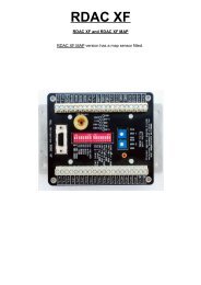
Picture of the <strong>MGL</strong> servo<br />
Other servo systems<br />
<strong>MGL</strong> provides the “<strong>MGL</strong> <strong>Avionics</strong> universal servo protocol” document to interested parties<br />
allowing special application servos to be constructed or existing servos to be modified to be<br />
able to be used with the <strong>MGL</strong> <strong>Avionics</strong> <strong>autopilot</strong> system.<br />
Page 8
Engaging and disengaging the <strong>autopilot</strong><br />
The <strong>autopilot</strong> can be engaged and disengaged in several ways:<br />
●<br />
●<br />
●<br />
Via the EFIS keypad<br />
Via <strong>autopilot</strong> engage/disengage switch (this requires fitting of an I/O extender).<br />
Via optional <strong>autopilot</strong> control panel (Planned item)<br />
The <strong>autopilot</strong> will refuse to engage if:<br />
●<br />
●<br />
●<br />
●<br />
●<br />
●<br />
The servos are interface using a <strong>MGL</strong> <strong>Avionics</strong> COM extender and no communications<br />
to this unit can be established.<br />
A digital servo is used and it reports a position beyond its control limits (Trio only)<br />
A digital servo is used and it reports a fault<br />
A digital servo is used and no information is received (RX fault)<br />
Selected navigation source does not have valid solution<br />
No AHRS is connected<br />
The <strong>autopilot</strong> will disengage if:<br />
●<br />
●<br />
●<br />
●<br />
●<br />
●<br />
●<br />
●<br />
The disengage function on the EFIS keypad is activated (button push)<br />
Engage/disengage switch is pressed (switch connected to I/O Extender)<br />
Disengage button is pressed on optional <strong>autopilot</strong> control panel<br />
A digital servo reports that it has reached its control limit<br />
A digital servo reports a slipping clutch or torque overdrive for 1 second<br />
Active navigation source has been lost<br />
Power is removed from a digital servo (causes RX fault)<br />
Connection to <strong>MGL</strong> COM Extender is lost (if this unit is required to control servos)<br />
Preflight check of the <strong>autopilot</strong> installation<br />
Menu level 2 provides a preflight check function.<br />
Each servo (excluding power control) will be moved to its extreme control limits and when<br />
complete left it its neutral position. At the same time, the display will show the action taken so<br />
servo direction can be verified.<br />
Note: This function will not be available if an active flight has been detected. Airspeed must<br />
read below 30mph. In addition, a confirmation will need to be acknowledged before this<br />
Page 9
function will commence. Under no circumstances should this function be activated in flight.<br />
The function can exited by pressing any key on the EFIS which will also disengage the<br />
servos.<br />
During the servo preflight check, verify the correct directional operation of each servo. The<br />
controls must not bind and the servos must not slip in any position. With the servos<br />
disengaged, verify that full <strong>manual</strong> control is present.<br />
If a yaw control servo is being used, the pre-flight check will confirm if you would like the Yaw<br />
servo to be activated as part of the pre-flight. If your yaw servo is connected to a nose gear<br />
steering system, the combined force required to control the yaw may exceed the ability of the<br />
servo. If this is the case with your installation, select to not engage the yaw servo.<br />
The yaw servo should be periodically tested on the ground with offending drag removed if<br />
required. On smaller aircraft this could be achieved by lifting the nose gear during the test.<br />
Installation<br />
Installation of the <strong>autopilot</strong> system consists of four steps:<br />
●<br />
●<br />
●<br />
●<br />
Obtain information from suitable sources as to best or recommended location and<br />
means for servo installation – if this is not possible, perform a test flight as outlined in<br />
the next chapter to determine suitability of the aircraft for installation of an <strong>autopilot</strong>.<br />
Physical installation of the servos, electrical and mechanical connections<br />
Ground based configuration of the <strong>autopilot</strong> system<br />
Test flight based calibration of the <strong>autopilot</strong> system<br />
Physical installation of the servos<br />
This phase starts with the identification of a suitable location for each servo. In many cases<br />
the aircraft manufacturer may have predetermined a suitable location and control linkage.<br />
Installation of the servo should be carried out by a suitably qualified aircraft technician.<br />
●<br />
●<br />
●<br />
●<br />
The servo needs to be installed on a rigid platform. It must not move under any<br />
expected mechanical load.<br />
Control linkages must be installed such that there is no play between servo bell crank<br />
and controls. Any play introduced here can seriously affect the <strong>autopilot</strong>s ability to fly<br />
the aircraft properly.<br />
Electrical wiring should be installed to aircraft standards using suitably dimensioned<br />
cable. Please consult with the servo manufacturer for recommended wire types and<br />
core dimensions.<br />
Servo power must be routed via a circuit breaker or switch easily accessible to the<br />
pilot. Servos will disengage if power to them is removed.<br />
Page 10
Servo driven and undriven ranges<br />
Applicable: Trio Gold Standard Servo<br />
The Trio servo provides about +/- 40 degrees of active driven range from neutral position.<br />
When the servo is not engaged the servo arm can move in a much larger arc.<br />
The ideal installation will coincide the undriven (large) range with the full stop-to-stop range of<br />
the control surface so that the servo, once engaged is able to drive about 50%-70% of the<br />
range of the control surface. This is particularly important for higher performance aircraft. This<br />
improves the position accuracy and resolution of the servo system when very small<br />
adjustments may be needed in flight.<br />
Further considerations:<br />
With the control surface in neutral position, the servo arm must be as close to neutral as<br />
possible. There are 4 possible positions of the arm depending on how you mount the servo<br />
arm. If none of these positions are satisfactory, consider drilling four additional arm mounting<br />
holes to allow use of the arm in an offset position.<br />
The servo arm provides three hole positions to mount the control linkage. Consider drilling a<br />
further hole in a more suitable position to lower the active driven range of the servo on the<br />
control surface if required.<br />
Post installation checks:<br />
DO NOT FLY THE AIRCAFT UNTIL THE FOLLOWING POST INSTALLATION CHECKS<br />
HAVE BEEN CARRIED OUT AND FULL AND CORRECT FUNTIONS HAVE BEEN<br />
Page 11
OBSERVED:<br />
●<br />
●<br />
●<br />
Verify that no controls are binding during any position of the flight controls<br />
Verify that the servos when not engaged will not restrict movement of any flight<br />
controls including maximum limits of the flight controls<br />
Verify that the servos, once engaged, have as close to zero tolerance as possible<br />
when moving the control surfaces. VERIFY THIS. With the <strong>autopilot</strong> engaged, move<br />
the control surfaces by hand and ensure that there is no significant play. If any play is<br />
found, recheck your control linkages and install better or more suitable parts if<br />
required. Control linkage play may seriously limit the <strong>autopilot</strong>s ability to control your<br />
aircraft, in particular where pitch control is concerned.<br />
Pre-installation test flight<br />
Unless a suitable, known good servo installation is used (for example a series built aircraft<br />
with existing <strong>autopilot</strong> installations), it is recommended to test fly the aircraft before installation<br />
as follows here. Please note that this is a guide only and may need modification to suit the<br />
particular aircraft.<br />
The main aim is to fly the aircraft <strong>manual</strong>ly in exactly the same fashion that the <strong>autopilot</strong><br />
would. If you are installing a two-axis system and want to use aileron and elevator controls<br />
without pilot assisted rudder and power input, ensure that your aircraft can actually be flown<br />
that way. If you cannot, the <strong>autopilot</strong> will not be able to do so either !<br />
Using the above example, fly the aircraft to a stable, straight and level condition, then move<br />
your feet off the rudder pedals and refrain from adjusting power. Attempt to keep the aircraft<br />
on your current heading or ground track and exactly on your current altitude using aileron and<br />
elevator control only. Important: Use only small control corrections and feed these in gently,<br />
emulating a servo as best you can. If you find you can control your aircraft this way in<br />
moderate turbulence while keeping the speed relatively constant proceed to the next step:<br />
Intercept a new heading 90 degrees from your current heading using only aileron and<br />
elevator, use a turn rate that you feel comfortable with – we suggest around 2 to 3 seconds<br />
per degree (approximately rate one turn). If you find you can perform this maneuver fine with<br />
gentle control inputs proceed to the next step:<br />
From a straight and level position, attempt a climb to a new altitude (perhaps 500 feet above<br />
where you are now). Take note of your climb rate (feet per minute) and airspeed. Decide on a<br />
climb rate that results in best climb and a good speed without you needing to adjust power.<br />
Note down your result as you will be entering this in the <strong>autopilot</strong> pitch setup.<br />
Now repeat the same for a descent. Again, take note of your speed and descent rate and<br />
choose a combination that is most suitable for your aircraft without power adjustment.<br />
Remember these values for the pitch setup.<br />
It is acceptable to climb and decend with <strong>manual</strong> power adjustments. If you choose to operate<br />
the <strong>autopilot</strong> this way, use appropirate power settings and note your climb and decent rates.<br />
You will used these as target vertical speed settings for the <strong>autopilot</strong> pitch control.<br />
Page 12
Possible issues and suggested solutions:<br />
If your aircraft does not turn well without rudder input, try turning it with rudder only – will the<br />
ailerons self-center due to aerodynamic forces If you find you can turn your aircraft well<br />
without active aileron input you may be able to connect the bank servo to the rudder rather<br />
than the ailerons.<br />
Difficulty holding altitude due to engine power effects. This can be a bothersome issue and<br />
may be related to the amount of power your engine produces at various propeller loads<br />
coupled with an uneven torque curve of the engine. Here is a typical scenario based on a<br />
particular aircraft we used during the <strong>autopilot</strong> development:<br />
You start off with a low power setting (economy cruise) and you are holding altitude. The<br />
aircraft ascends a bit and you correct by a slight nose down attitude change. The engine now<br />
has a slightly lower load and RPM increases, the engine produces more power and instead of<br />
descending back to your target altitude your speed and lift increases so you ascend even<br />
more. More nose down worsens the effect. Eventually you find some equilibrium where you<br />
can hold altitude but only at a much higher speed where drag starts to help you from<br />
increasing speed.<br />
The reverse is also true – pitch up the nose and you slow down, more engine load – slower<br />
RPM, less engine power and you might find you start descending in a nose high attitude at<br />
slow speed rather than gaining altitude, the effect you had hoped for.<br />
The above scenario is often related to two stroke engines but can also affect four stroke<br />
engines that are “lugged” by a propeller with a too high pitch.<br />
If your aircraft behaves as above, it may not be possible for a two axis <strong>autopilot</strong> to even hold<br />
altitude properly, never mind climb and descend. In this case you may need to control power<br />
<strong>manual</strong>ly to assist the <strong>autopilot</strong> – a control you may find you need to do even when flying<br />
without <strong>autopilot</strong> to remain within target speed and altitude.<br />
As an alternative, you need to install an automatic power/RPM control (governor) or select a<br />
<strong>autopilot</strong> characteristic that includes throttle control.<br />
Issues related to aircraft stability:<br />
Traditional capture and track <strong>autopilot</strong>s can only be used with any measure of success on<br />
aircraft that are neutrally stable. If you aircraft is subject to a yawing moment when<br />
proceeding through the yaw-neutral position or a pitch moment when proceeding through<br />
pitch-neutral or significant stick force reversal based on angle-of-attack or speed changes, it<br />
is unlikely that you will be able to use this type of <strong>autopilot</strong> with any satisfaction.<br />
Aircraft like this can still be flown using an <strong>autopilot</strong> but tend to need full authority systems<br />
using fast servos that can instantly and proportionally correct any attitude deviation. Often,<br />
<strong>autopilot</strong>s for these types of aircraft are purpose-build and designed for a particular aircraft.<br />
Example: B2 Stealth bomber.<br />
Ground based configuration of the <strong>autopilot</strong> system<br />
During this phase you select the <strong>autopilot</strong> character and individual servo configurations.<br />
Page 13
The <strong>autopilot</strong> setup menu is accessible via the setup menu. Please note that some functions<br />
in this menu cannot be selected if a flight is active or airspeed shows above 30 mph.<br />
For each servo select the servo type and electrical connection source.<br />
Trio <strong>Avionics</strong> digital servos are controlled using RS232 serial data connections. The <strong>MGL</strong><br />
<strong>Avionics</strong> COM Extender provides four suitable serial ports. RS232 ports available on the EFIS<br />
cannot be used for Trio servos. Only COM Extender serial ports may be used for Trio servos.<br />
Each RS232 port provides a bidirectional communications link. The TX connection sends<br />
position and other data to the servo while the RX connection receives position and status data<br />
from the servo. If <strong>MGL</strong> servos are used on the Enigma, these can be connected to either the<br />
built in RS232 serial port 1 or serial port 4 on the COM Extender. In case of <strong>MGL</strong> servos on<br />
the Enigma, multiple servos are wired to a single RS232 port.<br />
PWM servos can be connected to the <strong>MGL</strong> <strong>Avionics</strong> COM Extender. Up to four PWM servos<br />
can be controlled. PWM servos can be considered as roll, yaw, power or lift servos. PWM<br />
servos should not be considered for pitch servos as these need to be engaged at a known<br />
position and this is only possible with digital servos.<br />
<strong>MGL</strong> <strong>Avionics</strong> servos on the XTreme, Voyager, Odyssey or “iEFIS” systems must be<br />
connected to the CAN interface. If more than one CAN interface exists on the EFIS, CAN<br />
interface number one must be used.<br />
Once the servo type and connection location has been selected, a corresponding<br />
configuration menu becomes available for that servo. For example, once you have allocated a<br />
bank servo, you will be presented with the Bank control setup menu.<br />
Selecting <strong>MGL</strong> servos<br />
It is recommended that you select a single type of servo for all functions.<br />
Note: Only <strong>MGL</strong> servos can be selected as Yaw servo. XTreme and Enigma do not support a<br />
Yaw servo.<br />
It is possible to mix servos of different types but this is not supported by <strong>MGL</strong> <strong>Avionics</strong>.<br />
Page 14
On the Enigma EFIS you can select <strong>MGL</strong> servos to be controlled via the built in RS232 port 1<br />
or you can choose to use Port 4 on the COM extender module.<br />
Identifying a <strong>MGL</strong> servo<br />
If <strong>MGL</strong> servos are selected, you will enable functions that will allow you to “identify” the<br />
servos. The servos need to be configured so they know what function they are assigned to.<br />
You can identify a servo if the <strong>autopilot</strong> is not engaged and no flight is active.<br />
In order to identify a servo (assign its function), only one servo is allowed to be connected.<br />
Please temporarily disconnect all other servos. Once you have a single servo connected you<br />
can use the “identify bank or pitch servo” functions.<br />
Example: You have the bank servo connected and powered. You then send the “Identify bank<br />
servo” command by selecting the relevant function.<br />
You will receive a confirmation message. If you are satisfied that all is well, press “1” to<br />
continue.<br />
After a few seconds you will be shown a message either confirming that the servo has been<br />
successfully configured or that no data has been received. If the procedure is not successful,<br />
please check your power supply and signal wiring from the EFIS to the servo.<br />
Once successful, you can proceed with the pitch servo in similar fashion.<br />
Before you can use the <strong>MGL</strong> servos you must identify them using the procedure<br />
described here. You can repeat this procedure and reassign servos as needed.<br />
Page 15
If you change servos or re-assign servos you must perform the identification<br />
procedure and select servo positions. Servos are unique and internal position<br />
numbers vary between servos.<br />
Page 16
Configuring the roll (bank) servo<br />
<strong>MGL</strong> <strong>Avionics</strong> servo setup<br />
Trio <strong>Avionics</strong> servo setup<br />
Bank servo direction<br />
Not used for <strong>MGL</strong> servo.<br />
Here you select the servo rotation direction. This depends on your installation. The direction is<br />
identified as CW (clockwise) or CCW (counter clockwise) as specified by the servo<br />
manufacturer to achieve a right bank.<br />
The servo direction in usually selected after performing the servo preflight test and noting the<br />
control movement vs. the intended movement. If the preflight screen is showing a left bank<br />
and your controls are moving for a right bank, change this setting.<br />
Target rate of turn<br />
Select your desired target rate of turn when capturing a new heading.<br />
Typical turn rates range from 2.0 to 3.0 degrees per second. A rate of 3.0 degrees per second<br />
corresponds to a rate one turn (360 degrees in two minutes).<br />
This value is used for large heading errors, for smaller errors this value is suitably scaled<br />
down to ensure smooth track intercept and hold.<br />
For fast aircraft, it is recommended to choose lower rates of turn to avoid the bank angle from<br />
getting too steep.<br />
Bank servo torque<br />
This entry will only show if you have the <strong>MGL</strong> <strong>Avionics</strong> servo selected. Here you select the<br />
maximum torque the servo will be able to hold before slipping. 100% is the maximum possible<br />
torque. Lower this number if you need the servo to slip at a lower torque setting. You should<br />
select a setting that allows an easy override of the servo by the pilot but it should remain high<br />
enough so it will not slip during higher control force loads that may be experienced during<br />
turbulence or out-of-trim conditions.<br />
Page 17
Bank servo Magnitude<br />
This setting selects the amount of servo movement for a given bank angle error (the error<br />
between desired bank angle and actual bank angle). This value is selected during a test flight<br />
(next chapter). Set this value to “10” before the first flight. A higher value produces more servo<br />
movement. The aim is to find a value that results in rapid correction of an error without overcorrection.<br />
Typical values are from 10 to 30.<br />
Heading control:...<br />
This entry is also available if the external ARINC <strong>autopilot</strong> has been selected (Odyssey,<br />
Voyager or Explorer).<br />
Using this setting you select the amount of bank angle to apply to correct a given track error.<br />
This allows you to select a “gentle” or “forceful” intercept.<br />
Select: Slow, Medium or Fast to best suit your aircraft.<br />
Bank neutral position trim<br />
This entry will only be available if you are using a PWM servo. Here you select the servo<br />
position to be used when engaging the <strong>autopilot</strong>. This position is normally selected during a<br />
test flight, trimming out any unwanted turn. Ensure that you start with the servo engaging the<br />
ailerons in approximately neutral position and refine the setting in flight.<br />
To use this function in flight, the <strong>autopilot</strong> must not be engaged (this function will not operate if<br />
the <strong>autopilot</strong> is engaged). If you activate this function the bank servo will engage at the<br />
current servo neutral position – note that other servos will not engage.<br />
Adjust the neutral position until any tendency to turn has been tuned out. This should best be<br />
done during calm flight conditions as turbulence may mask the neutral position.<br />
The bank servo will disengage as you deselect this function or exit the menu.<br />
Bank left limit / Bank right limit<br />
You cannot use or test the <strong>MGL</strong> <strong>Avionics</strong> servos until you have completed the<br />
following procedure:<br />
These entries show if you have a <strong>MGL</strong> servo selected.<br />
These functions are used to set the left and right limits as well as the required servo direction.<br />
Move the stick to the maxiumum left bank position you would like the <strong>autopilot</strong> to fly (this may<br />
be slightly less than the maximum left bank position that can be flown). You should see the<br />
current position shown in the range of 0 to 4095 as you move the stick. Select the function<br />
when you have reached the desired position. This will copy the current position into the limit<br />
field. Repeat this procedure for the right bank position. It does not matter which side you do<br />
first and you can do this as many times as needed.<br />
Note: You need to exit all menus to permanently store these settings.<br />
If you do not see the current position field number changing with servo arm position, please<br />
check that the servo is powered and that the serial communications link has been connected<br />
correctly. Also ensure that you have selected the correct port on the COM Extender for this<br />
Page 18
servo.<br />
Recommended first settings:<br />
Target rate of Turn: Slower aircraft: 3.0, faster aircraft: 2.0<br />
Bank Servo torque: As needed to ensure pilots ability to override servo.<br />
Bank Servo magnitude: 10<br />
Heading control: Medium<br />
Page 19
Configuring the pitch servo<br />
<strong>MGL</strong> <strong>Avionics</strong> servo setup<br />
Trio <strong>Avionics</strong> servo setup<br />
Pitch servo direction<br />
This function is not available for <strong>MGL</strong> <strong>Avionics</strong> servos.<br />
Here you select the servo rotation direction. This depends on your installation. The direction is<br />
identified as CW (clockwise) or CCW (counter clockwise) as specified by the servo<br />
manufacturer to achieve a pitch up.<br />
The servo direction in usually selected after performing the servo preflight test and noting the<br />
control movement vs. the intended movement. If the preflight screen is showing a pitch up<br />
and your controls are moving for a pitch down, change this setting.<br />
Low ASI for climb (lower nose)<br />
Select the minimum allowable airspeed during a climb. The <strong>autopilot</strong> system will control the<br />
pitch gyro during a climb such that when this airspeed limit is reached, a pitch down<br />
command will be issued to regain airspeed above this value.<br />
Airspeed has priority over ascent or descent rate.<br />
Please choose this value carefully to prevent issues during climbing. Airspeed will reduce<br />
during climbs if power is not added. Choose a value that is well above stall speed but not high<br />
enough to interfere with the climb.<br />
High ASI for descent (nose up)<br />
Select the maximum allowable airspeed during a descent. The <strong>autopilot</strong> system will control<br />
the pitch gyro during descent such that when this airspeed limit is reached, a pitch up<br />
command will be issued to retain airspeed below this value.<br />
Page 20
Airspeed has priority over ascent or descent rate.<br />
Target VSI for ascent<br />
Select the desired vertical rate of climb for ascent to a new flight altitude. This rate will be<br />
used as target if the new altitude is relatively far away.<br />
Avoid the temptation to select a climb rate that is higher than what your aircraft can sustain.<br />
Target VSI for descent<br />
Select the desired vertical rate of descent to a new flight altitude. This rate will be used as<br />
target if the new altitude is relatively far away.<br />
Select a target rate of descent that is achievable using elevator control only, taking into<br />
account maximum airspeed as selected for the descent.<br />
Pitch servo torque<br />
This entry will only show if you have the <strong>MGL</strong> <strong>Avionics</strong> servo selected. Here you select the<br />
maximum torque the servo will be able to hold before slipping. 100% is the maximum possible<br />
torque. Lower this number if you need the servo to slip at a lower torque setting. You should<br />
select a setting that allows an easy override of the servo by the pilot but it should remain high<br />
enough so it will not slip during higher control force loads that may be experienced during<br />
moderate turbulence.<br />
Altitude control:...<br />
This entry is also available if the external ARINC <strong>autopilot</strong> has been selected (Odyssey,<br />
Voyager or Explorer).<br />
This setting adjust the speed that a pitch angle change may take. Higher values will result in a<br />
more aggressive change of pitch angle to follow a given vertical rate. Lower values result in a<br />
softer rate of pitch angle change.<br />
Select: Slow, Medium or Fast to best suit your aircraft.<br />
Pitch angle control magnitude<br />
This setting sets the amount of servo movement to apply for a given pitch angle change.<br />
If this setting is too low, the aircraft will take too long to change pitch angle and is not able to<br />
hold a desired pitch angle. If the value is too high, the pitch control can overreact resulting in<br />
a rapid and forceful oscillation around the pitch axis.<br />
Higher performance aircraft or aircraft that are very pitch sensitive (very small amounts of<br />
control movement result in a large pitch angle change) will need smaller settings (typically<br />
around 5-8) while slower aircraft tend to use values around 8 -15.<br />
This is the first and most critical calibration item that needs to be set as described below.<br />
Page 21
Pitch change to VSI reaction<br />
This setting informs the <strong>autopilot</strong> how long it will take for a pitch control surface change to<br />
affect the desired vertical rate change. This is related in part to the aircraft's mass and in part<br />
to the effectiveness of the aircraft's pitch control surface (elevator).<br />
Pitch up limit / Pitch down limit<br />
You cannot use or test the <strong>MGL</strong> <strong>Avionics</strong> servos until you have completed the<br />
following procedure:<br />
These entries show if you have a <strong>MGL</strong> servo selected.<br />
These functions are used to set the pitch up and down limits as well as the required servo<br />
direction. Move the stick to the maxiumum pitch up position you would like the <strong>autopilot</strong> to fly<br />
(this may be slightly less than the maximum up position that can be flown). You should see<br />
the current position shown in the range of 0 to 4095 as you move the stick. Select the function<br />
when you have reached the desired position. This will copy the current position into the limit<br />
field. Repeat this procedure for the pitch down position. It does not matter which you do first<br />
and you can do this as many times as needed.<br />
Note: You need to exit all menus to permanently store these settings.<br />
If you do not see the current position field number changing with servo arm position, please<br />
check that the servo is powered and that the serial communications link has been connected<br />
correctly. Also ensure that you have selected the correct port on the COM Extender for this<br />
servo.<br />
Recommended first settings<br />
Low ASI: Slightly above the aircraft's stall speed.<br />
High ASI: Slightly below or at the aircraft's maximum cruise speed.<br />
Target VSI for ascent: 400 ft/min or as suitable for aircraft.<br />
Target VSI for descent: 400 ft/min or as suitable for aircraft.<br />
Altitude control: Medium.<br />
Pitch Angle control magnitude: 10.<br />
Pitch change to VSI reaction: Medium.<br />
Page 22
Configuring the Yaw servo<br />
Yaw can only be supported if an <strong>MGL</strong> servo is fitted. It cannot be used with Trio or PWM<br />
servos.<br />
Engage mode<br />
This function allows you to select the desired engage mode of the yaw control.<br />
Yaw control can be disabled, set to engage and disengage with the remainder of the <strong>autopilot</strong><br />
or it can be selected to behave completely independent from the <strong>autopilot</strong> (in which case you<br />
need to engage yaw control yourself).<br />
Yaw servo torque<br />
Here you select the maximum torque the servo will be able to hold before slipping. 100% is<br />
the maximum possible torque. Lower this number if you need the servo to slip at a lower<br />
torque setting. You should select a setting that allows an easy override of the servo by the<br />
pilot but it should remain high enough so it will not slip during higher control force loads that<br />
may be experienced during moderate turbulence.<br />
Yaw servo magnitude<br />
Select the amount of rudder movement to apply for a given yaw error. A number that is too<br />
high will result in yaw instability due to over-control while a number too low will result in<br />
indifferent yaw control.<br />
Yaw control<br />
This setting should be related to the reaction time of your aircraft to rudder input.<br />
Yaw trim is:<br />
Select the slip indicator position that you would like the yaw control to target. Normally this<br />
would be “ball in center” but you have the ability to choose a position for ball left or right in<br />
Page 23
steps of 1/50 of the full range of movement. This can be of advantage to certain aircraft that<br />
exhibit yaw instability with the ball in the center.<br />
Important note: “Ball in center” relates to the actual slip indicator before any on-screen<br />
correction may have been applied (some EFIS systems allow you to “center” the ball<br />
regardless of its actual position – the yaw control uses “actual” position).<br />
Yaw left/right limit and servo center<br />
You cannot use or test the <strong>MGL</strong> <strong>Avionics</strong> servos until you have completed the<br />
following procedure:<br />
These functions are used to set the yaw left and right limits as well as the required servo<br />
direction and the yaw center (rudder center).<br />
Move the rudder to the maximum left yaw position you would like the <strong>autopilot</strong> to fly (this may<br />
be slightly less than the maximum left yaw position that can be flown). You should see the<br />
current position shown in the range of 0 to 4095 as you move the rudder. Select the function<br />
when you have reached the desired position. This will copy the current position into the limit<br />
field. Repeat this procedure for the yaw right and servo center position. It does not matter<br />
which you do first and you can do this as many times as needed.<br />
Note: You need to exit all menus to permanently store these settings.<br />
If you do not see the current position field number changing with servo arm position, please<br />
check that the servo is powered and that the serial communications link has been connected<br />
correctly.<br />
Note: Unlike the pitch and bank servos which are limited to less than 180 degrees<br />
movement of the servo arm (typical usable range tends to be 120 degrees unless a<br />
capstan servo is used) – the yaw servo may be utilized up to 340 degrees (20 degrees<br />
less than a full rotation).<br />
Page 24
First servo tests<br />
Within the system setup menu you will find the “servo test and checks” menu.<br />
Here you will find a set of functions that will allow you to engage and move the servos and<br />
also observe the data that is sent back from the servo.<br />
Example: Bank servo test and checks<br />
Use the provided functions to move the servo arm to the positions provided. Ensure that<br />
servo movement is smooth and no danger exists that could result in binding controls or<br />
jamming of control surfaces.<br />
Ensure that with the servo engaged there is no noticeable play between control surface and<br />
servo arm. Every small servo arm movement must result in a corresponding movement of the<br />
control surface.<br />
Below the selections, data received back from the servo (digital servos only) will be displayed.<br />
The <strong>autopilot</strong> will not engage if data from a digital servo is not received.<br />
You must guarantee that no reason exists that could result in servo or servo linkage to the<br />
control surface causing any form of danger to the aircraft in case of malfunction or any other<br />
cause. Ensure that the pilot will be able to take control from the servo in an emergency under<br />
any and all circumstances.<br />
Ground based testing of the <strong>autopilot</strong> system<br />
If this is your first installation using the COM extender, first ensure that the COM extender is<br />
operational. Ensure that it is connected to any one of the two USB host connectors on the<br />
back of the EFIS. Switch the EFIS on.<br />
As you switch the EFIS on, the RED LED on the COM Extender should light and stay on for<br />
Page 25
about 5 seconds. It should then start flashing twice per second. If the LED does not light at all,<br />
does not start flashing or if it flashes very fast then there is a problem. Do not proceed until<br />
you have resolved the issue.<br />
With the servos connected and the COM Extender LED flashing twice per second, apply<br />
power to the servos. The servos should not engage at this stage.<br />
Perform the <strong>autopilot</strong> preflight check. This is an automated procedure accessible from the<br />
main menu level 2.<br />
The bank and pitch servos will be activated in turn and each will move to its maximum limits<br />
and then center. During this time, the EFIS will inform you of the action it is taking, for<br />
example “Bank left”. Ensure that the control surfaces of your aircraft are moving in the correct<br />
direction. If they are not, correct this by setting the corresponding servo direction setting in the<br />
<strong>autopilot</strong> setup menu.<br />
Use the <strong>autopilot</strong> preflight check repeatedly to verify that all mechanical linkages are<br />
performing correctly and are not binding or have excessive play.<br />
While the preflight check is operating, physically move the control surfaces by hand against<br />
the servo force to locate any play. If you find significant play, please fix the cause before<br />
attempting a test flight. The <strong>autopilot</strong> cannot perform correctly if there is excessive play in the<br />
controls.<br />
This may also be the correct time to adjust the servo torque. Please refer to the <strong>manual</strong> of the<br />
servo manufacturer on how to adjust the torque. Correct torque is achieved if you can<br />
override the servo with fair ease using the control stick but it it firm enough not to cause the<br />
servo to slip in turbulent flight.<br />
The <strong>autopilot</strong> is designed to disengage if it detects a servo slipping for more than one second.<br />
This can be used as a convenient method to disengage the <strong>autopilot</strong> and it the recommended<br />
method as this results in your hand on the control as the <strong>autopilot</strong> disengages.<br />
If you have PWM servos connected, use the neutral positioning functions provided in the<br />
<strong>autopilot</strong> setup menus to set an approximate position. You will fine tune this position during<br />
flight. Please note: <strong>MGL</strong> <strong>Avionics</strong> does not recommend the use of PWM servos for pitch<br />
applications and recommends the use of digital servos for all functions.<br />
If your <strong>autopilot</strong> prelight tests have been completed satisfactory, you can consider a first test<br />
flight as outlined in the next chapter.<br />
Test flight based calibration of the <strong>autopilot</strong> system<br />
During this phase you calibrate each servos response characteristic to match your aircrafts<br />
flight dynamics and the servo control linkage to its corresponding control.<br />
While there may be more than one way to go about this, we recommend the following<br />
Page 26
for pitch as it is not possible to engage them at their current position.<br />
The first item that needs to be calibrated is the PID controller that controls the aircraft's pitch<br />
angle. For this we start by setting the Pitch angle control Magnitude to “5”. Ensure that<br />
during this calibration relatively calm flying conditions are present.<br />
Ensure that the pitch servo is enabled and that the pitch servo direction is set correctly as<br />
determined during ground testing.<br />
Engage the <strong>autopilot</strong> in “Engage, hold current altitude” mode. .<br />
Once engaged, open the Pitch setup menu again and start increasing the Pitch angle control<br />
Magnitude slowly. At some point you will notice that the pitch angle will start to oscillate<br />
(Nose moves up and down and with every cycle it gets worse). This is the point where too<br />
much control is present. Note the Magnitude number and reduce it by approximately 30%.<br />
The <strong>autopilot</strong> should now be able to hold any desired pitch angle.<br />
Example: The aircraft starts a pitch oscillation at a magnitude setting of 12. Reduce the<br />
number to 8 or 9. The <strong>autopilot</strong> should now be able to hold the pitch angle without any sign of<br />
oscillation. Reducing the number further is permissible but not lower than about 50% of the<br />
value it took to start the oscillation. If the number is too small the servo will move too slowly<br />
and the <strong>autopilot</strong> may not be able to correct pitch angle errors fast enough. This can degrade<br />
the <strong>autopilot</strong>'s responses particularly in turbulent conditions.<br />
Once a suitable value for the Pitch angle control Magnitude is found, it should not be<br />
necessary to change it again unless you change anything in the mechanical servo linkage.<br />
Disengage the <strong>autopilot</strong>.<br />
Select the altitude control as desired to “slow, medium or fast”. This controls how rapid pitch<br />
angle is allowed to change, for example if you have set the altitude bug to a new altitude and<br />
want the <strong>autopilot</strong> to follow (assuming the <strong>autopilot</strong> is enaged in “altitude hold mode”).<br />
If the control is set too low, performance will degrade and the <strong>autopilot</strong> is not able to hold<br />
altitude properly. In this case you will find a slow phugoid around the target altitude that may<br />
get worse with every cycle. This is due to the <strong>autopilot</strong> not being allowed to change pitch<br />
angle fast enough.<br />
Note for users of Trio servos:<br />
For aircraft with relatively sensitive pitch reaction it is required that the servo linkage uses one<br />
of the inner holes of the servo arm. The reason is that the servo has limited finite accuracy<br />
and tends to jitter somewhat. This may result in relatively large un-commanded movement of<br />
the elevator surface and instability of the pitch control. By using one of the inner holes you<br />
reduce this effect leading to better pitch control and better altitude holding.<br />
Note that this applies only to the Trio servo, not to the <strong>MGL</strong> servo.<br />
Basic roll and pitch angle control algorithm<br />
The desired bank angle is calculated from the current bank angle and the desired rate of turn<br />
to intercept a given heading. This bank angle is used as the flight director's bank angle. The<br />
bank angle is a calculation based on:<br />
a) The desired turn rate (calculated from the current heading error)<br />
Page 28
) The forward speed (ASI) of the aircraft.<br />
c) The currently measured bank angle.<br />
The system uses the vertical speed ascent and descent settings as guide. These settings will<br />
be used for relatively large changes in target altitude. For small changes, these settings are<br />
suitably scaled down. If you are exactly at target altitude, the <strong>autopilot</strong> will attempt to hold a<br />
vertical speed of zero feet per minute.<br />
The <strong>autopilot</strong> follows the flight director (In fact, the flight director is an integral part of the<br />
<strong>autopilot</strong>).<br />
The flight director determines the desired pitch angle to fly depending on the following factors:<br />
a) The desired vertical speed which is based on the current altitude error.<br />
b) The forward speed (ASI) of the aircraft.<br />
c) The current pitch angle.<br />
Page 29
Interpreting vertical aircraft movements under <strong>autopilot</strong> control<br />
Increasing, fast phugoid oscillations – Disengage the <strong>autopilot</strong> immediately and lower the<br />
Pitch angle control magnitude before engaging the <strong>autopilot</strong> again.<br />
Similar oscillations of the bank angle are also possible if the bank servo magnitude is set too<br />
high.<br />
Oscillations happen if the amount of servo movement is too large to correct a given pitch or<br />
bank angle error.<br />
Once your <strong>autopilot</strong> is matched to your aircraft<br />
When you are satisfied with your <strong>autopilot</strong> setups, please take some time to note down your<br />
various <strong>autopilot</strong> setups for future reference.<br />
We at <strong>MGL</strong> would be very interested in your setup values and the type of aircraft you fly and<br />
would like to share your experience with pilots of similar aircraft that may ask us for suitable<br />
starting values. Please contact us at info@mglavionics.co.za.<br />
Trouble shooting and known issues<br />
Menu level 2 contains a <strong>autopilot</strong> status viewer which gives a lot of information on what the<br />
<strong>autopilot</strong> is trying to do and current aircraft attitude measurement results.<br />
This is the list of currently know issues we are aware of:<br />
Engine torque effects<br />
Some engines may react with large power output changes related to pitch and speed<br />
changes. This may oppose the <strong>autopilot</strong>s attempts at altitude correction to a large degree.<br />
The only solution is pilot control of engine power or an <strong>autopilot</strong> that has control over the<br />
engine throttle.<br />
These effects tend to be worse with two-stroke engines.<br />
Typical effect:<br />
Aircraft is slightly above target altitude. AP lowers nose. Speed increases. Engine is unloaded<br />
allowing increased RPM and more power is produced. Instead of descending, aircraft gains<br />
altitude. Autopilot compensates with even more “nose down”. Eventually airframe drag assists<br />
and counters the increased power and the aircraft starts to intercept the target altitude again<br />
but at increased speed. Depending on the engines torque curve the engine may now maintain<br />
Page 30
an increased power setting even if throttle was not changed.<br />
The reverse of the above is also possible but can be worse as it is possible to slow the aircraft<br />
to a high nose attitude with reduced power making it impossible to regain target altitude<br />
without the pilot changing throttle position.<br />
PWM servos<br />
PWM servos cannot be monitored by the <strong>autopilot</strong>. This means they need to be engaged at a<br />
predefined position. This position can be adjusted via the setup menus. It is not possible to<br />
monitor servo slip. Generally, PWM servos are not suited for pitch control applications.<br />
Prerequisites<br />
The following prerequisites and parts are required to allow the <strong>autopilot</strong> to function correctly:<br />
SP-4, SP-5 or SP-7 AHRS in correctly installed and operating environment. Note: these units<br />
MUST be set to the 0.1 degree resolution data output mode, the <strong>autopilot</strong> will refuse to<br />
engage if the AHRS is not set to operate in this mode.<br />
SP-2, SP-6 compass (only used if GPS not operational).<br />
<strong>MGL</strong> <strong>Avionics</strong> COM Extender if using Trio servos or <strong>MGL</strong> servos on an Enigma and you<br />
cannot use the built in RS232 serial port 1.<br />
Compatible EFIS with latest software installed (check on www.<strong>MGL</strong><strong>Avionics</strong>.co.za for updates<br />
and current version numbers).<br />
Servos<br />
Compatible servos:<br />
Trio <strong>Avionics</strong> Gold standard digital servo.<br />
<strong>MGL</strong> <strong>Avionics</strong> servo.<br />
Navaid PWM servo and any other PWM servo that can accept a 100Hz PWM signal of 1-2mS<br />
pulse width at TTL levels (positive pulse).<br />
Please contact the manufacturer of a given servo for installation hardware, mounting brackets<br />
and advice for specific aircraft.<br />
Autopilot messages<br />
The <strong>autopilot</strong> can fail to engage with any of the following messages:<br />
AP fail: No AHRS<br />
No AHRS detected. The <strong>autopilot</strong> needs a AHRS like a SP-4 or SP-5 to operate.<br />
AP fail: AHRS data not compatible<br />
AHRS has been detected but is not set to produce correct data. Please ensure that you have<br />
the 0.1 degree AHRS selected in the “Horizon setup menu”.<br />
AP fail: No COM extender AP RX<br />
Page 31
COM extender not detected.<br />
AP fail: Pitch servo - no RX<br />
No data received from pitch servo – check servo power and wiring.<br />
AP fail: Bank servo - no RX<br />
No data received from bank servo – check servo power and wiring.<br />
AP fail: Yaw servo - no RX<br />
No data received from bank servo – check servo power and wiring.<br />
The <strong>autopilot</strong> can disengage with any of the following messages:<br />
AP disengage - Lost HSI<br />
No horizontal navigation signal available.<br />
AP disengage - Lost GSI<br />
No vertical navigation signal available.<br />
AP disengage - Lost AHRS<br />
Lost bank/pitch information from AHRS, AHRS not operational.<br />
AP disengage - Lost COMEX<br />
Lost connection to COM extender<br />
AP disengage - Bank limits<br />
Servo reports that maximum active control range of servo arm has been exceeded<br />
AP disengage - Bank clutch<br />
Bank servo clutch detected slipping for 1 second or longer<br />
AP disengage - Bank fault<br />
Bank servo communications fault – no response from servo<br />
AP disengage - Pitch limits<br />
Servo reports that maximum active control range of servo arm has been exceeded<br />
AP disengage - Pitch clutch<br />
Bank servo clutch detected slipping for 1 second or longer<br />
AP disengage - Pitch fault<br />
Pitch servo communications fault – no response from servo<br />
Page 32
AP disengage – GPS AHRS<br />
The EFIS system is not currently using a AHRS to measure aircraft attitude. The EFIS is<br />
using the GPS to estimate attitude based on the GPS flight path. This form of attitude cannot<br />
be used as a base to control the aircraft.<br />
Electrical installation of servos (Navaid, Trio <strong>Avionics</strong>)<br />
Servos are powered by the aircrafts power supply bus. Typically this bus supplies either 12V<br />
or 24V DC. Ensure that your servos are compatible with the DC supply available.<br />
Ensure that your aircrafts power supply is sufficient to supply your servos peak power<br />
demand. Use power cables of sufficient diameter to supply the required current without<br />
causing undue voltage loss.<br />
DANGER: Ensure that your servos supply ground is secure at all times. Loss of ground<br />
(ground fault) my cause extensive damage to connected systems. Please read notes on<br />
preventative measures related to ground faults.<br />
Servo positive power supply should be routed via a latching switch that is easily accessible by<br />
the pilot and clearly marked “Autopilot servo power: On/Off”.<br />
Page 33
The above drawing shows the installation for a Trio Gold standard digital servo and a PWM<br />
servo (in this case a Navaid servo).<br />
The communications link for the Gold standard servo is bi-directional, similar to RS232 but<br />
without negative voltage signals. In order for this to operate securely, it must be ensured that<br />
the ground of the COM-extender (available on pins 5 of each Rs232 connector) is at the same<br />
electrical potential as the servos own ground. Please ensure that you are using a sufficiently<br />
thick ground wire for the servos so the voltage potential at the servo will not be raised while<br />
the motor is operating.<br />
The <strong>autopilot</strong> is designed to disengage if it is not able to receive data from the servo.<br />
In case of PWM servos, there is no feedback from the servo back to the <strong>autopilot</strong> and the<br />
<strong>autopilot</strong> will not disengage in case of a servo fault as it is not able to detect this.<br />
It is highly recommended that 33 ohm resistors of 1/2W rating are inserted into the ground<br />
connections from each servo to the COM Extender ground as indicated in the drawing. These<br />
resistors will prevent excessive ground current from flowing from the servo though the COM<br />
extender and EFIS which could cause damage.<br />
These ground currents will occur if for some reason the servo looses its own supply ground<br />
while connected to +12V.<br />
Note: Servo communications cables must not be routed close to or alongside audio cables<br />
from an intercom system as the signals traveling in these cables may cause interference. It is<br />
advised to use shielded cable with the shield itself connected at one location only. The shield<br />
must not carry any current as this will result in the shield radiating possible interfering signals.<br />
Page 34
<strong>MGL</strong> <strong>Avionics</strong> USB COM Extender and <strong>autopilot</strong> servo interface<br />
Page 35
Electrical installation of servos (<strong>MGL</strong> <strong>Avionics</strong>)<br />
Full details on the <strong>MGL</strong> servo and its installation are published in the “Servo user <strong>manual</strong>”<br />
available for download from the <strong>MGL</strong> <strong>Avionics</strong> website.<br />
Basic electrical installation is repeated here.<br />
Installation of the <strong>MGL</strong> servo differs depending on whether the Enigma EFIS is used or any<br />
other EFIS is used. In case of the Enigma, you will be using the RS232 interface to connect to<br />
the servo. In the setup you can specify either the internal RS232 port 1 or Port 4 of a<br />
connected COM extender module.<br />
Note that it is possible to control multiple servos through a single RS232 interface.<br />
Page 36
Note the installation requirement for a 33 ohm resistor in the ground line to the EFIS. This<br />
resistor is required to avoid the possibility of a high current flow into the EFIS in case of a<br />
ground fault (loss of ground connection) of a connected servo. Note, in most cases the servo<br />
ground would be the same as the EFIS ground. In this case it is permissible NOT to wire the<br />
ground connection at all. You would only wire the RX and TX lines. This has a further<br />
advantage as no ground loop is created which in some cases may cause radio interference<br />
issues.<br />
Page 37
Installation of the <strong>MGL</strong> servo on EFIS systems supporting a CAN interface requires a single<br />
twisted cable pair to connect the servos with the EFIS CAN interface.<br />
Please note that CAN requires termination resistors to be fitted to the ends of a cable run and<br />
that any branches from the cable must be short stubs.<br />
If short cable runs are used, it is usually possible to install just a single resistor at any point in<br />
the cable.<br />
At least one resistor must be installed. This forms an essential part of the CAN interface and it<br />
does not work at all if this resistor is not fitted.<br />
Longer cable runs (in excess of a few feet) must use resistors on both ends of the cable. Do<br />
not fit more than two resistors.<br />
Typical resistor values are 120 ohms. The exact value is not very critical but the combined<br />
value (two resistors in parallel) must not be less than 60 ohms. (120 / 2).<br />
<strong>MGL</strong> Servo LED indicator<br />
Please note that the <strong>MGL</strong> servo has a red LED light.<br />
This light will flash if the servo is being addressed by the EFIS. If the LED is steady on, there<br />
are two possible causes:<br />
a) The servo has never been “identified” and is in virgin state as delivered by the factory<br />
(please perform the servo identification as outlined in this <strong>manual</strong>).<br />
b) There is no communications due to a wiring issue.<br />
Page 38
Using the <strong>autopilot</strong><br />
The <strong>autopilot</strong> can be engaged in various modes and these can be transitioned between. The<br />
following text assumes that both bank and pitch servos are fitted. In case only one servo is<br />
fitted, some functions will not be available:<br />
Autopilot control on Voyager and Odyssey EFIS systems<br />
If the <strong>autopilot</strong> is enabled and configured, select the <strong>autopilot</strong> control menu using the left array<br />
of function keys.<br />
Pressing “1” will engage the <strong>autopilot</strong> in current heading and altitude hold mode.Heading is<br />
derived from GPS heading corrected for local variation to obtain magnetic heading. This<br />
means that heading is independent of you compass installation.<br />
Altitude is derived from your altimeter and thus responds to local pressure settings. Your<br />
altitude bug is set to the nearest 50 ft boundary.<br />
Pressing “2” will engage your current navigation solution (primary “HSI”). Typical sources for<br />
your “HSI” are GPS navigation (Goto or routes), VOR, GVOR, ILS, GLS or heading bug. You<br />
select the required navigation source using the left function keys and you enable these<br />
sources for use using the relevant setup menus.<br />
Pitch control source is selected as shown:<br />
Altitude hold takes the current altitude and sets your altitude bug to this altitude.<br />
Altitude preselect takes altitude as currently selected on the altitude bug.<br />
VSI hold will attempt to hold the current vertical speed (usefull for long climbs and descents).<br />
Flightplan vertical navigation will take altitude cues from an active route containing altitude<br />
directives.<br />
Pitch attitude hold will attempt to hold your current pitch attitude. This can be used to adjust<br />
your “pitch servo magnitude” in the <strong>autopilot</strong> setup.<br />
Pressing “9” will engage the <strong>autopilot</strong> in a mode where it will attempt to hold the current<br />
altitude while reversing course. Once the reverse course has been intercepted, the mode is<br />
identical to “1” Engage, straight and level.<br />
Page 39
On the second page you will find the Yaw control if this is configured on your system. You can<br />
engage and disengage yaw control independently from the remainder of the <strong>autopilot</strong>. You<br />
can configure the yaw control in the <strong>autopilot</strong> setup to engage automatically with the <strong>autopilot</strong><br />
(but you still have independent control) or it can be set to be completely independent from the<br />
<strong>autopilot</strong>.<br />
Autopilot control on Enigma systems<br />
Autopilot control on Enigma systems is very similar to that on Odyssey/Voyager systems<br />
providing much the same functionality in a slightly different presentation.<br />
The <strong>autopilot</strong> control menu is activated using “SHIFT” followed by “Menu” and then selecting<br />
“Autopilot control”.<br />
The “extended keypad” menu<br />
As Enigma does not have a function keypad on the left side (as Odyssey/Voyager), a<br />
substitute is available by pressing “SHIFT” followed by “Menu”:<br />
This menu provides functions to select the currently active navigation solution, you can set<br />
the heading and altitude bugs by direct numeric entry and you can access the <strong>autopilot</strong><br />
control menu.<br />
Disengaging the <strong>autopilot</strong><br />
Once the <strong>autopilot</strong> is enaged, the <strong>autopilot</strong> control menus provide an option to disengage the<br />
<strong>autopilot</strong>.<br />
Typically however, the <strong>autopilot</strong> is either disengaged by the pilot taking control of the aircraft.<br />
This causes one or more servos to slip which disengages the <strong>autopilot</strong> (Not available for<br />
PWM servos)<br />
Alternatively, the circuit breaker or switch feeding power to the servos is used to remove<br />
Page 40
power from the servos. This also disengages the servos and the <strong>autopilot</strong>. In case of PWM<br />
servos removing power disenages the servos but the <strong>autopilot</strong> still needs to be disenaged<br />
using the <strong>autopilot</strong> control menu. This us due to the fact that the <strong>autopilot</strong> does not have any<br />
form of feedback from PWM servos.<br />
Other forms of <strong>autopilot</strong> control<br />
Using a <strong>MGL</strong> <strong>Avionics</strong> I/O Extender it becomes possible to configure one or more push-button<br />
switches (momentary contact switches) to engage and disengage the <strong>autopilot</strong>.<br />
This requires creation of an I/O Extender script containing instructions on which inputs to use<br />
for which functions. The Script editor for this is available as free download from the <strong>MGL</strong><br />
<strong>Avionics</strong> website (www.<strong>MGL</strong><strong>Avionics</strong>.co.za) EFIS tools page.<br />
You need as minimum release 2 of the I/O Extender script editor.<br />
The script file, once created is installed into your EFIS using the “Installation tasks” menu.<br />
Autopilot behavior<br />
This chapter explains how the <strong>autopilot</strong> will react in certain cases:<br />
Activating a GPS “Goto” when not pointing to the destination<br />
You are flying on an arbitrary heading and select a GPS “Goto” that takes you in a new<br />
direction.<br />
At the very moment of activating the “goto”, the EFIS creates a track to the destination from<br />
the exact point of activation. As you are not pointing in this direction you will be immediately<br />
off track. The <strong>autopilot</strong> will now bank towards the track and attempt to intercept the track at an<br />
angle of about 45 degrees. At some distance from intercepting the track the <strong>autopilot</strong> will start<br />
gently vectoring towards the track. This distance is affected by your <strong>autopilot</strong> setup “Track<br />
force” setting.<br />
Climbing and descending<br />
Clean intercept of a target altitude is very dependent on your aircrafts power control. It makes<br />
a big difference how your engine reacts to propeller loading or if you have a constant speed<br />
propeller fitted.<br />
Regardless of this, for a clean ascent or descent power should be adjusted to maintain<br />
airspeed as required.<br />
The <strong>autopilot</strong> will attempt to intercept and hold climb and descent rates as you have set in the<br />
<strong>autopilot</strong> setup, be aware that if minimum or maximum speeds are exceeded the <strong>autopilot</strong> will<br />
abandon all attempts at vertical speed tracking and will either raise or lower the aircraft's nose<br />
so as to prevent undesired speeds.<br />
The set rates will only apply if you are more than about 100 ft away from the target altitude, if<br />
less than this the rates will start to taper off, ever rapidly in order to intercept zero feet per<br />
minute rate at the target altitude.<br />
Page 41
When controlling power, gradually increase or decrease power as required to avoid changes<br />
in speed, unless desired.<br />
If you are climbing and leave the engine at climb power, the <strong>autopilot</strong> is likely to overshoot the<br />
target altitude. The reason for this is the additional lift created as your aircraft speeds up due<br />
to the climb flattening out. Very similar to this, you will overshoot on a descent if you do not<br />
add power due to reduced airspeed and lift. The <strong>autopilot</strong> will attempt to fix up the overshoots<br />
but the correct procedure would be to prevent them from happening.<br />
Similar to non-<strong>autopilot</strong> flight, power control during ascending and descending is required in<br />
order to obtain a clean profile.<br />
Arriving at a waypoint or arriving at the last waypoint in a route<br />
If you do not disengage the <strong>autopilot</strong> when arriving at a destination, the <strong>autopilot</strong> will either fly<br />
a circle or a figure of eight depending on wind direction in order to repeatedly intercept the<br />
waypoint.<br />
Autopilot response in turbulence<br />
The <strong>autopilot</strong> controls actual pitch and bank angles with reference to the AHRS system, this<br />
allows the <strong>autopilot</strong> to stabilize the flight profile in presence of external disturbances such as<br />
caused by turbulence and thermal activity. The response is mainly limited by the speed of the<br />
servo. Depending on which type of servo you have fitted, different levels of stabilization can<br />
be expected.<br />
The <strong>autopilot</strong> algorithm is designed to allow increasing tolerance with respect to the target<br />
altitude as turbulence increases. In calm conditions altitude tracking is typically +/-20 ft, within<br />
this band the <strong>autopilot</strong> will be “lazy” in order to prevent excessive activation of the flight<br />
controls. In the presence of turbulence this band is gradually widened up to +/-50 ft to avoid<br />
unnecessary activity. While in the band, the <strong>autopilot</strong> will only make small adjustments to<br />
capture the target altitude. When outside the band, the <strong>autopilot</strong> will make a more determined<br />
effort to get onto target altitude.<br />
Engaging the <strong>autopilot</strong> if no navigation solution is selected<br />
If you engage the <strong>autopilot</strong> without a valid navigation solution, the <strong>autopilot</strong> will engage and<br />
track the current heading and set the altimeter bug to the current altitude.<br />
The <strong>autopilot</strong> will refuse to engage if there is no vertical guidance selected. In this case<br />
please select your GSI source as “altitude bug”.<br />
If the current navigation solution is “heading bug” and you engage the <strong>autopilot</strong>, the heading<br />
bug will be set to the current heading.<br />
Please note that the <strong>autopilot</strong> will use GPS based heading (GPS true track with local variation<br />
applied).<br />
Engaging the <strong>autopilot</strong> if a navigation solution is active<br />
If you engage the <strong>autopilot</strong> with an active navigation solution (I.e. your “HSI” is set to a valid<br />
Page 42
source) and the source is not “heading bug”, then the <strong>autopilot</strong> will engage the existing<br />
solution. If the current solution is “heading bug” then the heading bug will be set to the current<br />
heading.<br />
Performing a “direct goto” or activating a route with the <strong>autopilot</strong> engaged<br />
If the <strong>autopilot</strong> is engaged and using any navigation solution and you perform a GPS “goto” or<br />
activate a route, the <strong>autopilot</strong> will use the new navigation solution directly. There is no need to<br />
change navigation sources.<br />
Using VOR or ILS as source for the <strong>autopilot</strong><br />
The <strong>autopilot</strong> follows any navigation source selected on the primary “HSI”. This is the only<br />
source for the <strong>autopilot</strong> horizontal navigation. It follows that the <strong>autopilot</strong> will simply use<br />
whatever current source has been selected on the “HSI”. This means that you can use any<br />
navigation source, regardless if this is an internal or external source.<br />
Please note that you may need to setup the available sources as selectable for the HSI. This<br />
is done in the “setup HSI/GSI indicators” and “GLS/GVOR setup”. Depending on your sources<br />
available, you may also need to configure your “ARINC setup”.<br />
Vertical guidance sources<br />
In most cases vertical guidance is taken directly from the GSI (glide slope indicator) which is<br />
also active during altitude hold (effectively a zero angle glide slope). It follows that whatever<br />
source is selected for the GSI will affect vertical tracking.<br />
In most cases the altitude bug would be the altitude target.<br />
Autopilot usage requirements – safety checks and<br />
considerations<br />
No flight that will use the <strong>autopilot</strong> will be conducted without satisfactory pre-flight check of the<br />
<strong>autopilot</strong> and its systems.<br />
Autopilot setups should be verified for correctness before flight.<br />
The <strong>autopilot</strong> algorithms require correctly calibrated and functional airspeed input. If airspeed<br />
cannot be measured in flight (for example pitot tube icing), the <strong>autopilot</strong> must not be engaged<br />
as control responses may be incorrect.<br />
It must be possible for an independent system to disengage the <strong>autopilot</strong> if required. A power<br />
switch accessible to the pilot that powers the servos is acceptable.<br />
Pilots using the <strong>autopilot</strong> must be trained in the use and limitations of this <strong>autopilot</strong> system.<br />
Installation of all parts related to the <strong>autopilot</strong> system must be carried out to acceptable<br />
aviation standards and comply with safety requirements. All components must be accessible<br />
to regular pre-flight checks. Concealed linkages or servos that cannot be inspected without<br />
major effort are not acceptable.<br />
Servo installation must adhere to airworthiness requirements and should be performed in<br />
Page 43
consultation with the manufacturer of the aircraft to ensure safety and operation of the<br />
<strong>autopilot</strong> system and airframe.<br />
The <strong>autopilot</strong> system is not intended to be used<br />
during takeoff and landing of the aircraft.<br />
Page 44