RDAC X installation manual (800 KBytes) - MGL Avionics
RDAC X installation manual (800 KBytes) - MGL Avionics
RDAC X installation manual (800 KBytes) - MGL Avionics

You also want an ePaper? Increase the reach of your titles
YUMPU automatically turns print PDFs into web optimized ePapers that Google loves.
<strong>RDAC</strong> X<br />
Technical <strong>installation</strong> document<br />
Models:<br />
A – 4TC channels<br />
B – 12TC channels<br />
C – 4TC channels plus Manifold pressure sender<br />
D – 12TC channels plus Manifold pressure sender
<strong>RDAC</strong> X – general<br />
The <strong>RDAC</strong> X consists of two parts:<br />
The baseboard. This board contains one or two rows of friction lock screw<br />
terminal connectors.<br />
This part is intended to be installed on an aircraft firewall (engine<br />
compartment side).<br />
Models A and C contain one row of connectors.<br />
Models B and D contain two rows of connectors.<br />
The <strong>RDAC</strong> module. This module plugs into the baseboard and is held in place<br />
using nylon straps or bonding material. In the event of a failure, the module is<br />
quick and easy to replace.<br />
The <strong>RDAC</strong> module comes in two versions: One version has a manifold<br />
pressure sensor with stovepipe connector, the other does not have such a<br />
sensor.
The <strong>RDAC</strong> X power supply and data cable connection<br />
<strong>RDAC</strong> X Power supply<br />
The <strong>RDAC</strong> X requires supply from a 12V DC source. Voltages such as found<br />
in typical 12V nicad or lead-acid battery based <strong>installation</strong>s are acceptable.<br />
The <strong>RDAC</strong> X is designed to operate from 8VDC to 18VDC. Should your<br />
aircraft have a 24/28V system, you need to provide a 12V preregulator.<br />
In order to achieve maximum accuracy, it is important to route the power<br />
supply wiring correctly.<br />
It is important that the black wire is routed in as sort as possible manner to the<br />
engine block. The engine block should have a connection to the negative of<br />
the battery. Normally this connection is provided in the form of a heavy duty<br />
cable to allow for the considerable currents of an electric starter motor.<br />
Should your <strong>installation</strong> not have electric start, you will still need to provide<br />
this connection.
Do not route the black wire directly to the battery minus. This can lead to false<br />
readings on some senders. The black wire must be routed to the engine<br />
block. You must have a connection from the engine block to the battery<br />
minus.<br />
The red wire is to be connected to +12VDC. This connection would normally<br />
be provided via your aircrafts master switch or instrument power supply<br />
switch. This cable should not be connected to the battery positive terminal<br />
directly without a power switch as this would result in your battery being<br />
drained when the system is not in use.<br />
<strong>RDAC</strong> X function indicator<br />
The <strong>RDAC</strong> X has a red LED that will flash in an approximate 0.5-1 second<br />
interval if power has been supplied and the <strong>RDAC</strong> is functioning.<br />
<strong>RDAC</strong> X communications link<br />
The <strong>RDAC</strong> X has a serial data communications link that is optically isolated,<br />
i.e. it has no electrical connection to the <strong>RDAC</strong> electronics itself.<br />
This prevents any form of electrical current flowing in this cable in case of an<br />
electrical wiring fault in your aircraft, in particular ground faults.<br />
Connect the wire as indicated by color code on the rear of your instrument.<br />
You have three connections:<br />
Braid – electrically connected to ground by your instrument.<br />
Blue – the data line. Inverse polarity compared to RS232.<br />
Red – connected to +12V by the instrument. Used to power a pull-up resistor<br />
on the blue wire.<br />
<strong>RDAC</strong> X jumpers<br />
The <strong>RDAC</strong> X provides several jumpers to allow you to configure your rev<br />
counter. In the current release, two jumpers are provided while a further two<br />
are permanently closed.<br />
The jumper marked “ballast” switches a 220 ohm resistor into you rev counter<br />
line to ground (12V negative rail). This ballast may be required for some<br />
engines in particular Rotax engines. You should first try without the ballast<br />
(jumper removed). If you find the RPM display unstable insert the ballast by<br />
placing the link on the ballast terminals.<br />
The jumper marked “DC” will route the rev counter signal to the <strong>RDAC</strong> with a<br />
direct current connection. Removing the link will activate an AC connection.<br />
The AC connection can provide better signal detection in case your signal has<br />
a DC offset voltage.<br />
The best setting (link removed or not) is best found by experimentation.
Installation of the <strong>RDAC</strong> X<br />
The <strong>RDAC</strong> X must be installed with the following requirements met:<br />
a) The <strong>RDAC</strong> must not be exposed to direct engine vibrations. Never<br />
mount the <strong>RDAC</strong> on the engine itself. The baseboard is intended to be<br />
mounted on the aircrafts firewall or similar suitable structure.<br />
b) The <strong>RDAC</strong> must be installed so extreme heat from the engine cannot<br />
damage it.<br />
c) The <strong>RDAC</strong> must be mounted in a position where it is protected from<br />
any engine oils or other engine fluids including water.<br />
d) If required the <strong>RDAC</strong> should be mounted inside a protected enclosure<br />
if it is otherwise not possible to protect it from environmental exposure<br />
such as rain.<br />
e) All wires to the baseboard must be secured such that it is not possible<br />
for any wire to be damaged due to chafing or that any wire can loosen<br />
itself from its connection terminal.<br />
f) If the <strong>RDAC</strong> is operated in conditions that may lead to corrosion of<br />
exposed electrical metal parts, suitable protection is a mandatory<br />
requirement.<br />
g) The <strong>RDAC</strong> includes very good protection against voltage transients on<br />
the power supply. However, in cases where severe transients<br />
containing a large amount of energy are expected, additional, external<br />
protection may be required.<br />
h) All signal connections that terminate in any of the <strong>RDAC</strong> terminals<br />
must never be allowed to contain dangerous high voltages such as can<br />
be created by ignition systems or inductive devices. In particular never<br />
route such cables alongside HT ignition leads.<br />
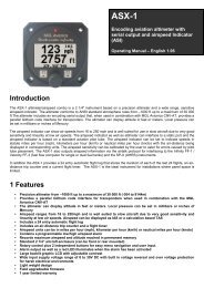
<strong>RDAC</strong> X principle wiring diagram<br />
The following diagram shows a basic connection sample for various sensors.<br />
The actual connection of sensors depends on your application and setup in<br />
the display unit (instrument).<br />
Normally, in cases of multiple EGT/CHT thermocouple sensors, EGT sensors<br />
start from TC channel 1 while the CHT channels follow.<br />
The starting channel for CHT channels depends on your instruments setup.<br />
CHT1/WTAUX3 is used for either a NTC type water temperature sender or<br />
the CHT probe of a Rotax 912/914 engine.<br />
CHT2/CarbIce/AUX4 is used for a LM335 based ice waring sensor or the<br />
second CHT probe of a Rotax 912/914 engine.
Red wire should connect to +12V via main<br />
instrument power switch<br />
RED<br />
Back wire is negative supply<br />
and must be routed VIA the<br />
engine block to the negative terminal<br />
of the battery / power supply<br />
BLACK<br />
Data cable<br />
yellow<br />
red<br />
EGT probes<br />
CHT probes<br />
2 x CHT (Rotax 912/914 engines)<br />
Additional EGT and CHT<br />
probes for 12 channel <strong>RDAC</strong><br />
Oil temperature sender<br />
Oil pressure sender<br />
In case of a two wire sender<br />
one wire connects to<br />
the engine block<br />
Fuel flow sender<br />
Fuel level senders<br />
Rev counter pickup wire<br />
Ballast resistor<br />
Variable<br />
(*1)<br />
DC<br />
Ballast<br />
Module<br />
(*1)<br />
(*1) Not provided on all models<br />
Variable setting<br />
(*1)<br />
<strong>RDAC</strong> X<br />
principle connection<br />
diagram
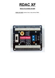
<strong>RDAC</strong> EMS unit thermocouple<br />
inputs<br />
Typical Thermocouple setup, here<br />
shown for four EGT probes. Please<br />
note that the probes are colour<br />
coded. Yellow wires must connect to<br />
the “+” terminals and the red wires<br />
must connect to the “-“ terminals.<br />
Thermocouple inputs – details<br />
The <strong>RDAC</strong> X EMS provides for up to twelve thermocouple inputs for use with<br />
EGT and CHT probes. Both K as well as J type probes can be used. K types<br />
are used for EGT probes while most CHT probes are also K types. Some<br />
makes of CHT probes are J type.<br />
Probe types are selected in the sender setup menu of your instrument.<br />
Important: Incorrect selection will lead to incorrect temperature display.<br />
The <strong>RDAC</strong> X EMS will accept both grounded and isolated thermocouple<br />
probes. Your only consideration in case of the more common grounded<br />
configurations is that you need to ensure that the thermocouple mounting<br />
position (Exhaust flange, etc) is at the same electrical potential as the<br />
negative supply line of the <strong>RDAC</strong> X (Black wire).<br />
Probe usage depends on your setup and kind of your instrument.<br />
Usage of thermocouple inputs with various display units:<br />
E2, Ultra L<br />
The first four thermocouple inputs are supported. These can be freely<br />
configured in the relevant setup menus. Normaly, thermocouple inputs from<br />
TC1 upwards are used for EGT probes, followed by CHT probes. For
example, a popular setup would be TC1 and TC2 are EGT, TC3 and TC4 are<br />
CHT. Channels TC5 to TC12 cannot be used with these instruments.<br />
Ultra X, UltraH<br />
These instruments support up to eight thermocouple inputs. You would thus<br />
use TC1 to TC8.<br />
With these instruments, EGT and CHT monitoring is configured in blocks. For<br />
example a popular configuration would be four EGT and four CHT probes.<br />
The EGT channels would start at TC1 and the CHT in this case at TC5.<br />
Channels TC9 to TC12 cannot be used with these instruments.<br />
Enigma<br />
All versions of Enigma supplied with engine monitor can support channels<br />
TC1 to TC12. Usage of these channels depends on how you configure the<br />
visual thermocouple monitors. We suggest that you use inputs TC1 and<br />
upwards for EGT probes and follow this with CHT probes. For example, for a<br />
six cylinder engine you might choose TC1 to TC6 as EGT and TC7 to TC12<br />
as CHT.<br />
RDAX X thermoucouple guidelines<br />
The thermocouple amplifier is a precision device providing full cold junction<br />
compensation and bow voltage correction. In addition the amplifier measures<br />
and corrects for its own errors. This results in very accurate measurements<br />
providing you install high quality probes. Here are some guidelines:<br />
EGT Probes: select probes that are made from 316 stainless steel and that<br />
use glass-fiber insulated conductors. Teflon insulated conductors as found in<br />
many cheap probes introduce errors as the insulation melts moving the<br />
measuring point towards the mounting bolt which transfers a lot of heat to the<br />
exhaust material. This results in under reading probes. Stay away from<br />
probes that use simple plastic heat shrink sleeving – it does not last. Choose<br />
probes that use a generous amount of stainless steel spring as strain relief.<br />
The Bolt itself should be stainless as well or it will rust very quickly.<br />
CHT probes: These are made from washers to fit spark-plug bases.<br />
Temperatures are considerably lower so most thermocouple cables will work<br />
without problems. The biggest area of concern should be the connection of<br />
the thermocouple cable to the washer. This often breaks after the spark plug<br />
has been changed a few times. Choose a probe that is suitably reinforced at<br />
this point for a long and trouble free life.<br />
EGT and CHT probes supplied by <strong>MGL</strong> <strong>Avionics</strong> are of highest quality. We<br />
recommend that you consider using our probes if at all possible.<br />
Warning: Four stroke engines produce much hotter exhaust gases compared<br />
to two stroke engines. Do not use EGT probes made from lower grade<br />
stainless steel (for example 310), these probes will not withstand the high<br />
temperatures and can fail as the metal gets very soft at <strong>800</strong> degrees C. Many
four strokes (such as the Rotax 912) will produce exhaust gases of up to 850<br />
degrees C.<br />
Important <strong>installation</strong> note:<br />
EGT and CHT probes use wire made from plain Iron and other basic metals.<br />
As a result these probes are not able to withstand much flexing of the wires<br />
due to engine vibrations. Avoid making nice looking coils or similar<br />
constructions that will result in excessive vibration or flexing of the wire. Route<br />
the cables from the probe points tightly along suitable engine mounting points<br />
eliminating any chance of unnecessary wire flexing during engine operation.
Connecting coolant temperature, oil temperature and oil<br />
pressure senders.<br />
This drawings shows the connection of a coolant temperature probe, a oil<br />
temperature probe and a oil pressure sender.<br />
Note that all of these probes require a good electrical ground connection to<br />
the engine block so they should never be installed using sealant or PTFE<br />
sealant tapes. The <strong>RDAC</strong> X black supply cable connection should also be<br />
wired to the engine block.<br />
The <strong>RDAC</strong> X supports various types of temperature senders and well as oil<br />
pressure senders. These are selected in the relevant sender setup menus of<br />
your instrument.<br />
Please note that the CHT1 and CHT2 terminals are used in case of a Rotax<br />
912 or 914 engine to interface to the two built in CHT senders. These senders<br />
are standard VDO oil temperarature senders.<br />
Coolant and oil temperature senders are mostly NTC resistors. These are<br />
resistors that vary their resistance with temperature. These senders come in a<br />
wide variety so ensure that the sender you are using is compatible with the<br />
instrument and that you have selected the correct probe type in the relevant<br />
setup menu.
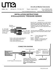
<strong>RDAC</strong> Fuel flow sender <strong>installation</strong><br />
Note: Direction of fuel flow<br />
Indicated by arrow on sender<br />
RED wire – Fuel Flow Sender Supply<br />
BLUE wire – Fuel Flow Sender signal<br />
Braid – Fuel Flow Sender Ground<br />
Braid<br />
BLUE<br />
RED<br />
Warning: Incorrect wiring can damage<br />
both the <strong>RDAC</strong> unit as well<br />
as the flow sender.<br />
The optional Fuel Flow Sender is highly<br />
recommended for use with Stratomaster<br />
instruments. It provides instantaneous<br />
readouts of hourly fuel usage, and both time and distance estimates on<br />
remaining fuel in flight. You can also verify the performance of your fuel pump<br />
during the pre-takeoff engine run up – a very valuable check !<br />
Further, it is possible to set up the instruments to calculate Fuel remaining by<br />
subtracting fuel used from a value entered when you filled your tank(s).<br />
In this case you may omit the <strong>installation</strong> of the optional fuel level sender.<br />
Please note that the <strong>installation</strong> of the Fuel Flow sender should be done in<br />
such a fashion that dirt or debris from the fuel tank cannot lodge inside the<br />
flow sender. These will not block you fuel flow but may lead to the impeller<br />
inside the sender jamming. It is usually sufficient to mount the Flow sender<br />
AFTER the fuel filter but before the fuel pump. It is a good idea to provide a<br />
small reservoir such as a primer bulb between the flow sender and the fuel<br />
pump.
Primer bulb or small reservoir<br />
Fuel filter<br />
Fuel Tank<br />
Fuel flow<br />
sender<br />
Fuel pump<br />
As indicated in the recommended fuel flow sender <strong>installation</strong> drawing, it can<br />
be of advantage to install the flow sender in such a fashion that the inlet<br />
points slightly down and the outlet points slightly up. This prevents vapor from<br />
forming a bubble inside the flow sender.<br />
We strongly recommend to mount the flow sender in such a fashion that the<br />
impreller rests on only one bearing. This is achieved if you mount the sender<br />
such that the surface with the arrow faces upwards.<br />
Mounting the sender like this results in the best performance at low flow rates<br />
as only very little friction is present.<br />
The flow sender is delivered with a small jet that can be installed in the flow<br />
sender inlet. Installation of this jet is recommended for engines with fuel flow<br />
rates lower than about 30 liters per hour. This would apply to most small two<br />
and four stroke engines.<br />
Stratomaster instruments are shipped with the Fuel sender calibration set for<br />
the jet installed. In a good <strong>installation</strong> you can expect about +/- 3% maximum<br />
flow reading error with this factor.<br />
You can calibrate the flow sender yourself to a higher degree of accuracy if<br />
you so desire.<br />
Recommended procedure to calibrate the fuel flow sender:<br />
Note: You must disable the Fuel Level sender if you have one installed first.<br />
Fill your tank exactly to a known level (for example 50 liters).<br />
Set your fuel level to 50 liters using the Main Menu. If required you may have<br />
to disable the fuel level sender first using the Mode Menu.<br />
Fly your aircraft for a period that you know will use approximately 20 liters of<br />
fuel. The exact fuel burn is not important, just burn about 20 liters of your fuel.<br />
At the end of your flight the instrument should give you a reading of how much<br />
fuel you have left – the reading should be about 30 liters left.<br />
Now place your aircraft in exactly the same position that you used when you<br />
first filled the tank and refill the tank to 50 liters using a measuring jug. You<br />
should find that you need 20 liters of fuel to refill to 50 liters.<br />
If you find that the instrument under or over reads the fuel used, you should<br />
perform a simple adjustment of the Fuel Flow sender calibration factor. This is<br />
outlined in the Owners Manual.
Example:<br />
Actual fuel used: 21.5 liters, Stratomaster fuel burn calculated 29.7 liters left in<br />
tank. This means the Stratomaster measured 50-29.7 = 20.3 liters. We are<br />
under reading by 1.2 liters.<br />
Default calibration factor in Fuel Flow setup (Basic device setup menu) =<br />
7000.<br />
Let the corrected calibration factor be X.<br />
X = (21.5 * 7000) / 20.3<br />
X = 7413.79<br />
The closest setting you can enter as factor is 7414. Enter it into the unit and<br />
you are done !<br />
Repeat the above procedure to verify that your flow sender is now reading<br />
correctly.<br />
Please note:<br />
Before you calibrate the flow sender ensure there are no problems with your<br />
<strong>installation</strong>. We find the senders are very accurate if everything is installed<br />
and working properly. If your fuel burn indication is out by a large amount you<br />
have a problem that you should not attempt to fix by fiddling with the<br />
calibration factor !<br />
Please ensure that no fuel vapor can be trapped inside the sender housing in<br />
the form of bubbles. Due to the low fuel flow rates the bubbles will prevent the<br />
tiny impeller from turning freely, You can verify the turning of the impeller. You<br />
should notice three dark spots that are just visible in the inside of the fuel flow<br />
sender. These are small magnets that are attached to the impeller. With fuel<br />
flowing you should see the magnets turning.<br />
The best defense against vapor bubbles is to install the flow sender in such a<br />
way that the bubbles can escape. The easiest way is to point the outlet<br />
slightly upwards and the inlet (with the jet) slightly downwards.<br />
Another possible problem is the fuel sender jet. When you install it, do not<br />
damage it. Use a drill bit of suitable diameter to push the jet all the way the<br />
opening of the jet must be just in front of the impeller.<br />
YOU NEED TO APPLY SOME FORCE TO INSERT THE JET ALL THE WAY.<br />
THE JET MUST BE LOCATED RIGHT IN FRONT OF THE IMPELLOR. YOU<br />
CANNOT PUSH THE JET TOO FAR.
(Fuel flow sender – continued from previous page)<br />
Using other Flow Senders<br />
It is quite possible to use Flow Senders other than the Stratomaster device. In<br />
this case ensure that the Sender outputs a 5V TTL square wave or a similar<br />
signal. The Stratomaster interface electronics will adapt to a variety of<br />
different voltages and pulse shapes as it contains a schmidt-trigger input<br />
stage. The calibration factor can be entered in a wide range making the unit<br />
particulary suited to other Flow senders.<br />
The supply output terminal for the Sender provides a positive, regulated 5 volt<br />
output. This may be used to power the Flow Sender provided the Sender will<br />
not draw more than 40 mA of current. Should your sender require a higher<br />
voltage or more current, then you must supply the sender from a different<br />
power source. Exceeding the rating on the Stratomaster Flow sender supply<br />
terminal can affect the operation on the unit negatively or even damage it.<br />
Recommended Calibration Factors for the <strong>MGL</strong> <strong>Avionics</strong> dual range flow<br />
sender:<br />
With jet installed = 7000. Recommended with flow rates below 30 liters/hour<br />
maximum.<br />
Without jet installed = 1330. Recommended with flow rates above 30<br />
liters/hour.<br />
Please refer to the leaflet included with the Flow Sender for information on<br />
pressure drop vs. flow rate, wetted materials etc.<br />
It is your responsibility to ensure that the flow sender used is<br />
compatible with the fuels you intend using. We have found the <strong>MGL</strong><br />
<strong>Avionics</strong> sender to be very compatible with automotive fuels used in<br />
South Africa, many of which contain methanol. 100LL AVGAS also<br />
appears not to harm the sender in any way. We have exposed a sender<br />
continuously to our automotive fuels for a duration of two years without<br />
any noticeable ill effect on the sender.<br />
However, despite this <strong>MGL</strong> <strong>Avionics</strong> or its appointed agents cannot<br />
assume responsibility for any incident or damage, even loss of life by<br />
whatsoever cause connected with the fuel flow sender or the<br />
Stratomaster Flight Instrument. Usage of this or other senders is your<br />
own sole responsibility.<br />
If you do not agree with the above statement you must not use the fuel<br />
flow sender.<br />
Note to Pilots: (Even though this is the <strong>installation</strong> <strong>manual</strong>)<br />
You must always have a visual indication of the fuel level available, either by<br />
means of a sight glass, direct tank observation or a known, reliable secondary<br />
fuel level gauge. Fuel level indication by means of calculated fuel burn is<br />
subject to errors both by entering incorrect starting fuel levels as well as
mechanical problems causing the flow sender impeller to turn too slowly,<br />
resulting in under reading fuel burn and thus over reading remaining fuel.<br />
As pilot in command of an aircraft it is your responsibility to ensure that you<br />
have sufficient fuel to reach your intended destination. Always ensure that you<br />
have a generous amount of reserve fuel and never use your reserve fuel<br />
except in an emergency if it is unavoidable.
<strong>RDAC</strong> Fuel injection system monitoring<br />
Fuel<br />
Injector<br />
+12V rail<br />
Join here to<br />
monitor injector<br />
Fuel injection control unit<br />
Typical low side fired<br />
fuel injection system<br />
Should you want to monitor fuel flow directly by means of measuring the fuel<br />
injector opening time, the above arrangement can be used.<br />
You can use both high or low fired injectors (most systems are low side fired<br />
as shown above).<br />
After you have connected the system as shown above you can proceed to set<br />
up the system. (don’t forget that you need a connection from the <strong>RDAC</strong><br />
ground terminal to the engine block (at the same potential as the battery<br />
negative).<br />
a) Select high or low side fired injector in the Mode Menu (InjectorH and<br />
InjectorL).<br />
b) Enable the flow sender in the Mode Menu.<br />
c) Select a suitable K-factor in the calibration menu to give you correct<br />
rate of flow. A good starting value may be in the 1500-2000 range.<br />
Increase to lower indicated flow and decrease to have a larger<br />
indicated flow.
Flow through the injectors may not be 100% linear with switching times due to<br />
various effects. However, it is possible to obtain very good performance from<br />
this flow monitoring system if you keep the following in mind:<br />
Calibrate the K-factor so flow indication is accurate during cruise, the period<br />
your engine spends most of its active time at.<br />
Ensure that you have a correctly working fuel pressure regulator. The more<br />
constant your fuel pressure, the more accurate the flow indication.<br />
Never use this or any other flow system as your only fuel level indication. This is not<br />
the intended purpose of a flow measuring system and this can be dangerous if for<br />
whatever reason incorrect flow is indicated.
Connecting fuel level sender(s)<br />
Typical float<br />
based level sender<br />
We recommend<br />
VDO senders<br />
Connect flange of sender to negative<br />
supply (ground). Dotted connection is<br />
for fuel level sender two.<br />
The Stratomaster <strong>RDAC</strong> X EMS permits the connection of one or two<br />
standard automotive fuel level senders. These senders can be obtained at<br />
automotive spares outlets at reasonable cost.<br />
When you choose a float level sender, ensure that you select a model that is<br />
sturdy and promises reliable and long lifetime. In particular, select a model<br />
that does not have any metal parts that can rust.<br />
The <strong>RDAC</strong> X EMS can interface to a large variety of these fuel level senders.<br />
It does not matter if the sender resistance increases or decreases with the<br />
fuel level as long as it changes. The calibration procedure outlined “Set fuel<br />
tank” in the owners <strong>manual</strong> describes in great detail the procedure to follow.<br />
In essence, the calibration procedure will measure the resistance of the fuel<br />
level sender at various fuel levels and then work out the readings in between<br />
those known settings.<br />
Typical fuel level senders that can be used with the <strong>RDAC</strong> X EMS have<br />
resistance ranges in the region of 100 ohms to 500 ohms.
You can connect capacitive senders as well. These generally come in two<br />
types: The first emulates a normal resistive probe and is simple to connect<br />
and use as a result.<br />
The second type has a voltage level output. These can be used if the voltage<br />
can be set to a range of about 0-4V. Higher voltage levels will result in the<br />
instrument assuming a problem.<br />
The <strong>RDAC</strong> X supports one or two fuel tank level senders. You need to enable<br />
these in the relevant setup menu of your instrument (usualy the mode setup<br />
menu).<br />
Safety Hazard ! Please read this:<br />
Be careful when installing fuel level senders into fuel tanks. Ensure that the<br />
fuel tank is completely empty when you proceed with the <strong>installation</strong>. Ensure<br />
that the fuel tank is well ventilated and does not contain any fuel vapors –<br />
these are highly explosive when mixed with air.<br />
Ensure that at all times the ground connection (the connection of the fuel level<br />
sender mounting flange) is securely connected to the aircraft frame (in case of<br />
a metal frame) and to the negative terminal of the battery. In addition the<br />
negative terminal of the battery must at all times be connected to the Supply<br />
ground terminal of the <strong>RDAC</strong> X EMS.<br />
Please note – this wiring is critical and must never break in flight. It would be<br />
possible to create electrical sparks in the fuel tank if your wiring is faulty or<br />
incorrect. The consequences of this can be imagined. This has nothing to do<br />
with the <strong>RDAC</strong> EMS itself but is a general hazard for any automotive fuel level<br />
sender <strong>installation</strong>.<br />
If you have no experience with electrical wiring, PLEASE delegate the task to<br />
a qualified automobile electrician or electronics technician.<br />
If you need to remove the <strong>RDAC</strong> X EMS, please first disconnect and secure<br />
the fuel level sender wire before disconnecting anything else.
Connecting the rev counter<br />
REV counter<br />
wire from<br />
ignition system<br />
After you have connected the rev<br />
counter terminal to the signal source you<br />
need to set the number of pulses per 10<br />
revolutions in the Calibration Menu.<br />
The calibration itself depends on your<br />
engine type and what kind of signal you<br />
are using. Typical sources are:<br />
Magneto coils (suitable signal at the kill<br />
Ballast resistor link<br />
switch).<br />
Primary (low voltage) side of ignition coil, at contact breaker or electronic<br />
ignition module.<br />
RPM counter output of electronic ignition systems (for example Bosh<br />
Motronic).<br />
RPM pickup devices such as hall-effect sensors on flywheels etc.<br />
Typical calibration settings are 10 or 20 for most engines. Other pulse counts<br />
per 10 revolutions are also possible for some engines.<br />
Note: The <strong>RDAC</strong> X EMS contains a 220 ohm ballast resistor that is in circuit if<br />
the indicated link is closed. Normally you would not need this. We have found<br />
a few Rotax engines that create a very noisy signal where you will need to<br />
use it. The problem manifests itself by several rev band regions giving<br />
unstable rev readings. Should you be unlucky enough to have one of these<br />
systems, please close the link with the supplied connector or solder the link<br />
closed.
The rev counter input on the <strong>RDAC</strong> can be used with signals from about 4Vpp<br />
to as much as 100Vpp. A noise filter is included that results in the input<br />
ignoring any noise signals as long as this is below the detection threshold of<br />
about 2.5Vpp. The input impedance of the rev counter input is approximately<br />
10Kohm. You can use series resistors as well as load resistors for<br />
applications that have unusual signals.
Rev counter pickup for Stratomaster instruments fitted to automotive engines<br />
Conventional contact breaker<br />
ingnition system<br />
Use the tacho<br />
line if your<br />
system has<br />
such a signal.<br />
Connect rev counter<br />
input on <strong>RDAC</strong> or<br />
instrument to this line.<br />
Ensure you have a<br />
connection from <strong>RDAC</strong><br />
ground or instrument<br />
ground to engine block.<br />
Electronic ignition system with conventional ignition coil<br />
Connect rev counter<br />
input on <strong>RDAC</strong> or<br />
instrument to this line.<br />
Ensure you have a<br />
connection from <strong>RDAC</strong><br />
ground or instrument<br />
ground to engine block.
Connecting the rev counter on a two<br />
stroke Rotax<br />
Typical connection in case of<br />
a Rotax two stroke engine with<br />
Ducati dual ignition.<br />
Grey wire<br />
from Rotax<br />
DCDI ignition<br />
Engine with generator<br />
such as Rotax 503,<br />
Rotax 582 etc<br />
Most instruments assume as a default that you will be connecting a Rotax<br />
with DCDI ignition system. Such a system produces 6 pulses for every<br />
revolution of the engine.<br />
Other engines can be used but you must adjust the rev counter calibration<br />
setting accordingly (Device basic setup menu).<br />
The value entered is for 10 revs. On some instruments a decimal point is<br />
shown in the setup for the rev counter calibration. If you have one of these,<br />
enter the number as pulses per revolution. For example, for the Rotax 503 or<br />
Rotax 582 you would enter 6.0.<br />
Rotax 503,582,618 DCDI - value 60 (6.0).<br />
Rotax 912,914 – value 10 (1.0).<br />
The rev counter input can be connected to a variety of different sources such<br />
as the low voltage side of a ignition coil (at the points contact breaker) or to<br />
rev counter outputs of fuel injection computers.<br />
Note: Some Rotax engines may require that the ballast resistor is in circuit.<br />
Close the relevant link on the <strong>RDAC</strong> Baseboard.
Connecting a Rotax 912
The Rotax 912/914 contains two built in NTC type CHT temperature senders.<br />
In addition oil temperature and oil pressure sender is provided as standard.<br />
Due to the fact that the 912 has two carburetors (one for each side of the<br />
engine), two EGT probes should be connected, one for each exhaust stack.<br />
You can connect four EGT probes if you like. You would use TC1 and 3 as<br />
one pair and TC2 and 4 as the other pair. Each pair monitors one side of the<br />
engine.<br />
CHT1 and CHT2 connect to the standard CHT senders, again one for each<br />
side. Connect oil pressure and oil temperature and you are done.<br />
In the Stratomaster Ultra and similar instruments, use “Engine quick select” to<br />
choose the 912 setup and then use “Engine detail setup” to change any<br />
settings to your liking.<br />
Connect the Rev counter wires (blue/yellow and white/yellow) as follows: One<br />
of the two wires needs to be connected to ground (engine block), the other to<br />
the REV counter input. For this engine we recommend that the ballast resistor<br />
is in circuit (link closed).<br />
Do not forget to set the “rev counter setup” in the “Basic setup menu” or<br />
“Calibration Menu” (depending on instrument type). Select a value of 1.0 as<br />
the engine generates one pulse for every revolution.<br />
Please note: Most of the senders are “grounded configurations” This means<br />
they connect electrically to the engine block. It is vital for good and stable<br />
readings that you connect the “Ground” terminal of the <strong>RDAC</strong> to the engine<br />
block using a short, good quality electrical connection.<br />
Never use sealant or PTFE tape on the threads of the senders. This may<br />
electically isolate the senders which will result in incorrect indications.<br />
The threads on these senders are expanding threads which are designed to<br />
create a tight metal to metal seal.
Connecting a Rotax 503 or 582<br />
This diagram shows EGT, CHT and water temperature sender locations and<br />
wiring based on a Rotax 582. This is a water cooled engine so CHT senders<br />
should be viewed as optional. For a Rotax 503 or similar aircooled <strong>installation</strong>,<br />
proceed similar but omit the water temperature sender and wiring.<br />
Please note that the ground connection (black wire) from the <strong>RDAC</strong> must be<br />
connected to the engine block as shown. Select a suitable point on your<br />
engine block for this connection.<br />
The engine block itself needs to be connected to the negative supply, in all<br />
cases this should be a direct connection to your batteries minus terminal. This<br />
should be a thick copper cable with a very low resistance and it needs to be<br />
as short as possible. This requirement is even more severe if you are using<br />
electric start as the very considerable currents required by the starter motor<br />
will be using this connection.
Connecting a Bendix magneto as RPM source<br />
AC/DC link<br />
Remove<br />
ballast resistor<br />
link<br />
The above drawing shows the connection required if you would like to connect<br />
a magneto as RPM source.<br />
Shown is a typical Bendix magneto as used on Lycoming and other aircraft<br />
engines. You should find a wire connected to a terminal on the magneto that<br />
originates from your magento kill switch (or starter switch). The terminal is<br />
often refered to as a “P-terminal”. Connect a wire as shown and connect this<br />
to the Rec counter input of the <strong>RDAC</strong>.<br />
We strongly recommend that a resistor is inserted into your wire as shown. A<br />
good value would be 10.000 ohms (10K). A normal 1/4 W resistor is just fine.<br />
The link on the <strong>RDAC</strong> for the ballast resistor should be removed (i.e. you do<br />
not want the ballast resistor in circuit).<br />
You can leave the AC/DC link resistor in circuit or you can remove it.<br />
Experiment if either option gives you better results.<br />
The above circuit can also be used on other magneto systems such as found<br />
on Jabiru and similar engines.