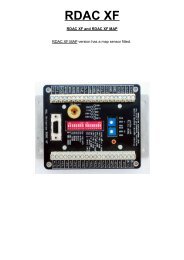
RDAC X installation manual (800 KBytes) - MGL Avionics
RDAC X installation manual (800 KBytes) - MGL Avionics
RDAC X installation manual (800 KBytes) - MGL Avionics

Create successful ePaper yourself
Turn your PDF publications into a flip-book with our unique Google optimized e-Paper software.
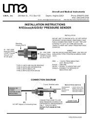
Do not route the black wire directly to the battery minus. This can lead to false<br />
readings on some senders. The black wire must be routed to the engine<br />
block. You must have a connection from the engine block to the battery<br />
minus.<br />
The red wire is to be connected to +12VDC. This connection would normally<br />
be provided via your aircrafts master switch or instrument power supply<br />
switch. This cable should not be connected to the battery positive terminal<br />
directly without a power switch as this would result in your battery being<br />
drained when the system is not in use.<br />
<strong>RDAC</strong> X function indicator<br />
The <strong>RDAC</strong> X has a red LED that will flash in an approximate 0.5-1 second<br />
interval if power has been supplied and the <strong>RDAC</strong> is functioning.<br />
<strong>RDAC</strong> X communications link<br />
The <strong>RDAC</strong> X has a serial data communications link that is optically isolated,<br />
i.e. it has no electrical connection to the <strong>RDAC</strong> electronics itself.<br />
This prevents any form of electrical current flowing in this cable in case of an<br />
electrical wiring fault in your aircraft, in particular ground faults.<br />
Connect the wire as indicated by color code on the rear of your instrument.<br />
You have three connections:<br />
Braid – electrically connected to ground by your instrument.<br />
Blue – the data line. Inverse polarity compared to RS232.<br />
Red – connected to +12V by the instrument. Used to power a pull-up resistor<br />
on the blue wire.<br />
<strong>RDAC</strong> X jumpers<br />
The <strong>RDAC</strong> X provides several jumpers to allow you to configure your rev<br />
counter. In the current release, two jumpers are provided while a further two<br />
are permanently closed.<br />
The jumper marked “ballast” switches a 220 ohm resistor into you rev counter<br />
line to ground (12V negative rail). This ballast may be required for some<br />
engines in particular Rotax engines. You should first try without the ballast<br />
(jumper removed). If you find the RPM display unstable insert the ballast by<br />
placing the link on the ballast terminals.<br />
The jumper marked “DC” will route the rev counter signal to the <strong>RDAC</strong> with a<br />
direct current connection. Removing the link will activate an AC connection.<br />
The AC connection can provide better signal detection in case your signal has<br />
a DC offset voltage.<br />
The best setting (link removed or not) is best found by experimentation.