RDAC X installation manual (800 KBytes) - MGL Avionics
RDAC X installation manual (800 KBytes) - MGL Avionics
RDAC X installation manual (800 KBytes) - MGL Avionics
You also want an ePaper? Increase the reach of your titles
YUMPU automatically turns print PDFs into web optimized ePapers that Google loves.
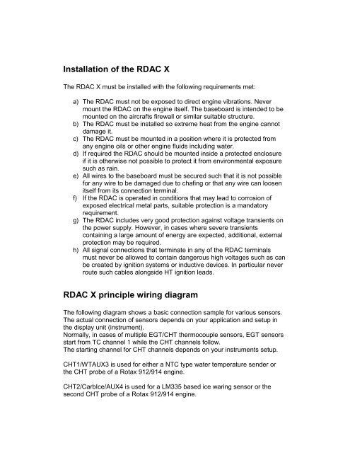
Installation of the <strong>RDAC</strong> X<br />
The <strong>RDAC</strong> X must be installed with the following requirements met:<br />
a) The <strong>RDAC</strong> must not be exposed to direct engine vibrations. Never<br />
mount the <strong>RDAC</strong> on the engine itself. The baseboard is intended to be<br />
mounted on the aircrafts firewall or similar suitable structure.<br />
b) The <strong>RDAC</strong> must be installed so extreme heat from the engine cannot<br />
damage it.<br />
c) The <strong>RDAC</strong> must be mounted in a position where it is protected from<br />
any engine oils or other engine fluids including water.<br />
d) If required the <strong>RDAC</strong> should be mounted inside a protected enclosure<br />
if it is otherwise not possible to protect it from environmental exposure<br />
such as rain.<br />
e) All wires to the baseboard must be secured such that it is not possible<br />
for any wire to be damaged due to chafing or that any wire can loosen<br />
itself from its connection terminal.<br />
f) If the <strong>RDAC</strong> is operated in conditions that may lead to corrosion of<br />
exposed electrical metal parts, suitable protection is a mandatory<br />
requirement.<br />
g) The <strong>RDAC</strong> includes very good protection against voltage transients on<br />
the power supply. However, in cases where severe transients<br />
containing a large amount of energy are expected, additional, external<br />
protection may be required.<br />
h) All signal connections that terminate in any of the <strong>RDAC</strong> terminals<br />
must never be allowed to contain dangerous high voltages such as can<br />
be created by ignition systems or inductive devices. In particular never<br />
route such cables alongside HT ignition leads.<br />
<strong>RDAC</strong> X principle wiring diagram<br />
The following diagram shows a basic connection sample for various sensors.<br />
The actual connection of sensors depends on your application and setup in<br />
the display unit (instrument).<br />
Normally, in cases of multiple EGT/CHT thermocouple sensors, EGT sensors<br />
start from TC channel 1 while the CHT channels follow.<br />
The starting channel for CHT channels depends on your instruments setup.<br />
CHT1/WTAUX3 is used for either a NTC type water temperature sender or<br />
the CHT probe of a Rotax 912/914 engine.<br />
CHT2/CarbIce/AUX4 is used for a LM335 based ice waring sensor or the<br />
second CHT probe of a Rotax 912/914 engine.


