
Create successful ePaper yourself
Turn your PDF publications into a flip-book with our unique Google optimized e-Paper software.
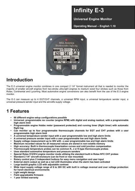
Infinity E-3Universal Engine MonitorOperating <strong>Manual</strong> – English 1.10IntroductionThe E-3 universal engine monitor combines in one compact 2 1/4” format instrument all that is needed to monitor themajority of smaller aircraft engines from two-stroke ultra-light engines to medium sized four strokes such as those fromRotax, Continental and Lycoming. Most automotive engine conversions can also benefit from the use of the E-3 enginemonitor.The E-3 can measure up to 4 EGT/CHT channels, a universal RPM input, a universal temperature sender input, auniversal pressure sender input and the aircrafts supply voltage.1 Features• 66 different engine setup configurations possible• Universal, programmable rev counter (engine RPM) with digital and analog readout, with a programmablehigh alarm limit• Programmable engine Hobbs meter (password protected) and running timer (flight timer) with automaticflight log• Can monitor up to four programmable thermocouple channels for EGT and CHT probes with a userprogrammable high alarm limit• A universal temperature sender input with a user programmable low and high alarm limits• A universal pressure sender input with a user programmable low and high alarm limits• Supply voltage measurement up to 30V with a user programmable low and high alarm limits• Maximum recorded values for all measured values are stored in non-volatile memory• High accuracy: Built in thermocouple linearization curves and cold junction compensation• Thermocouple temperature probes can be common K, J or E-type thermocouple probes• Uses standard automotive temperature and pressure senders• Special Rotax 912/914 engine monitor mode utilizing the standard built in Rotax NTC CHT probes• Standard 2 1/4” aircraft enclosure (can be front or rear mounted)• Rotary control plus 2 independent buttons for easy menu navigation and user input• External alarm output as well as a red LED illuminates when the alarm has been activated• Large backlit graphic LCD with adjustable contrast• Wide input supply voltage range of 8 to 30V DC with built in voltage reversal and over voltage protectionfor harsh electrical environments• Light weight design• Field upgradeable firmware• 1 year limited warranty
Infinity E-3 Operating <strong>Manual</strong> Page 43.2 Special Rotax 912/914 display modeIn this mode the temperature and pressure NTC inputs becomes CHT channel one and CHT channel 2 respectively. AllCHT setups must still be done under the “CHT SETUP” menu. The sender for the temperature and pressure setup mustbe set for “OFF”. A probe setting “NTC” must be selected for the probe setting in the “CHT SETUP” menu. The number ofEGT probes can be selected from 0 to 4.The reason for using the NTC inputs is that the sensors Rotax use are standard NTC temperature probes and not of athermocouple type.Maximum RPMreached markerAnalog RPM displayRPM AlarmDigital RPM readoutEGT ValueEGT alarmlimitCHT ValueMaximum valuereached indicatorMaximum valuereached indicatorCHT alarmlimitEGT groupindicatorTemperaturedisplay unitCHT groupindicator3.3 Start/Stop Flight DisplayPress the F1 key during the normal display mode to manually start/stop a flight. This key is only active if the E-3 is setupto select the manual flight option under the “FLIGHT LOG” setup menu.
Infinity E-3 Operating <strong>Manual</strong> Page 53.4 Contrast DisplayThis display can be accessed by pressing the F2 key during the normal display mode. This is a quick access key to thesame contrast menu as in the menu system.3.5 Maximum Values DisplayThis display can be accessed by rotating the rotary control clockwise during the normal display mode. Pressing the F1key will reset the maximum values to the current values. Pressing any other key will cause the E-3 to resume to thenormal display mode. To avoid false recordings, the maximum values function is only activated 10 seconds after theinstrument has powered up.Note: The permanent maximum values are stored in non-volatilememory and are recalled on power-up.3.6 Information DisplayThis display can be accessed by rotating the rotary control anti-clockwise during the normal display mode. This displayshows the current flight time, the hobbs timer and the supply voltage value. Pressing any key will cause the E-3 to resumeto the normal display mode.3.7 Maintenance TimerThe purpose of this function is to assist you in determining remaining hours until maintenance will be required. It is notintended as a replacement for the aircraft's maintenance log. It is therefore important that the aircraft's maintenance logbe maintained in the normal manner. You should further use your own discretion in performing maintenance earlier thanindicated should any aircraft performance problems arise.A maximum of 999 hours can be entered as a maintenance interval. The E-3 will deduct actual engine running time fromthe maintenance interval hours as set and will display the reminder message on startup when zero hours are remaining.The reminder message will automatically disappear after 5 seconds or if the pilot presses any key. Engine running timefor the purpose of the maintenance timer is defined as the run time where the engine RPM is greater than the preset RPMfor the Hobbs meter.
Infinity E-3 Operating <strong>Manual</strong> Page 64 Menu SystemPressing the rotary control button during the normal display mode will cause the E-3 to enter the menu system. Use theup/down keys or the rotary control to navigate through the menu system.4.1 Exit MenuPressing the rotary control on this menu item will cause the E-3 to exit the menu system. Allchanges made during navigation of the menu system will be saved in non-volatile memory on exitingthe menu system. If you remove power before exiting the menu the instrument will not save anychanges.
Infinity E-3 Operating <strong>Manual</strong> Page 74.2 Flight LogSelect whether the instrument should detect the start and end of flights automatically or if you wouldlike to do this manually. We recommend you select automatic flight detect. With automatic flightdetection, flights will start logging when the engine RPM is above the take-off limit. A flight isconsidered ended when the engine RPM is less than the RPM take-off limit for more then 30seconds.Move the highlight over the “DONE” option and press the rotary button to return to the main menu.Select this function to view the flight log. The flight log contains the duration ofeach of the last 24 logged flights. Duration is displayed in hours and minutes.Eight flights are displayed at a time. Use the up/down or the rotary control tonavigate through the log. Empty log entries are shown as “-----“.Note: You cannot select this function while a flight is in progress.Pressing the F1 key will erase all the flight log entries.Select whether you want the E-3 to automatically detect a flight or whether the pilot must press theF1 key to start/stop a flight. We recommend you select automatic flight detection.This menu option is only shown if the “DETECT” flight mode is selected. Enter the engine RPM takeoffthreshold that you want a flight log entry to start.4.3 Display SetupMove the highlight over the “DONE” menu item and press the rotary button to return to the mainmenu.Select this menu option to adjust the display contrast.Select this menu option to turn the backlight on or off.
Infinity E-3 Operating <strong>Manual</strong> Page 84.4 Hobbs MeterMove the highlight over the “DONE” menu option and press the rotary button to return to the mainmenu.Enter the RPM limit in which the Hobbs meter/maintenance timer must start counting.This function allows you to set the engine Hobbs meter to any value. Typically,you would use this function to set the Hobbs meter to the current known enginetime. Use the up/down or the rotary control to change the value. Press therotary control to accept and exit the menu option. If the Hobbs code is set toanother value beside zero, then the pilot will be prompted to enter the Hobbsaccess code before allowing him to change the Hobbs time. This feature isuseful for charted and flying school planes.This function allows you to set an engine maintenance timer. This timer is setin engine hours and it will count down to zero when the engine RPM is greaterthen the Hobbs RPM limit. A good use for this function is to set the hours untilyour next spark plug change or engine inspection. Use the up/down or therotary control to change the value. Press the rotary control to accept and exitthe menu option.Select if you would like the hour to be displayed in decimal fractions (0-99) or minutes (0-59).This setting influences the current flight time display and the flight log.This menu option allows you to change the Hobbs access code. You will first be prompted to enterthe current code followed by entering in a new code followed by re-entering the new code. If the newcode and the re-entered code is the same, then the Hobbs access code will be changed. Defaultcode is 0000.4.5 EGT (Exhaust Gas Temperature) SetupMove the highlight over the “DONE” menu option and press the rotary button to return to the mainmenu.
Infinity E-3 Operating <strong>Manual</strong> Page 9Select the number of EGT channels you want to use. Choices are from 1 to 4. The temperaturedisplay will configure itself to make best possible use of the available display size. Please note thatthe minimum number of EGT and CHT channels that can be displayed is 1 and the maximumnumber of EGT and CHT channels that can be displayed is 4.A selection between “HIGHEST” or “SCANNING” can be selected. If “HIGHEST “is selected thenthe current highest thermocouple temperature is displayed. If “SCANNING” is selected then the E-3will cycle through each thermocouple channel highlighting it as well as showing its temperature.This function sets the top end of your temperature bar graph. It has no effect on the actualtemperature range that can be displayed in the digital temperature readout. Select the range to bejust higher than the highest temperature you expect to measure using this channel.Select this function to “ON” if you want the bar graph display to show the upper half of thetemperature range only. This results in a higher resolution of the temperature range that you may beinterested in. For engine temperature measurements we recommend that you set this to “ON”.Adjust the temperature that you would like to use as an alarm limit. Any temperature above this limitwill activate the alarm. Active alarms will flash the affected channel and also activate the alarmcontact that you can use to switch a lamp on.Select whether you want to turn the alarm on or off. To avoid false activation of the alarms, thealarm function is only activated 10 seconds after the instrument has powered up.Select if you are using a K-type, J-type or E-type thermocouple probe for this channel. All probessupplied by <strong>MGL</strong> <strong>Avionics</strong> are K-Type. J-types are sometimes used with American made CHTprobes. All EGT probes are K-type. E-type probes are seldom used.Select whether you want all the temperature values to be displayed in degrees Fahrenheit (ºF) or indegrees Celsius (ºC).4.6 CHT (Cylinder Head Temperature) SetupMove the highlight over the “DONE” menu option and press the rotary button to return to the mainmenu.Select the number of CHT channels you want to use. Choices are from 1 to 4. The temperaturedisplay will configure itself to make best possible use of the available display size. Please note thatthe minimum number of EGT and CHT channels that can be displayed is 1 and the maximumnumber of EGT and CHT channels that can be displayed is 4.
Infinity E-3 Operating <strong>Manual</strong> Page 10A selection between “HIGHEST” or “SCANNING” can be selected. If “HIGHEST “is selected then thecurrent highest thermocouple temperature is displayed. If “SCANNING” is selected then the E-3 willcycle through each thermocouple channel highlighting it as well as showing its temperature.This function sets the top end of your temperature bar graph. It has no effect on the actualtemperature range that can be displayed in the digital temperature readout. Select the range to bejust higher than the highest temperature you expect to measure using this channel.Select this function to “ON” if you want the bar graph display to show the upper half of thetemperature range only. This results in a higher resolution of the temperature range that you may beinterested in. For engine temperature measurements we recommend that you set this to “ON”.Adjust the temperature that you would like to use as an alarm limit. Any temperature above this limitwill activate the alarm. Active alarms will flash the affected channel and also activate the alarmcontact that you can use to switch a lamp on.Select whether you want to turn the alarm on or off. To avoid false activation of the alarms, thealarm function is only activated 10 seconds after the instrument has powered up.Select if you are using a K-type, J-type or E-type thermocouple probe for this channel. All probessupplied by <strong>MGL</strong> <strong>Avionics</strong> are K-Type. J-types are sometimes used with American made CHTprobes. All EGT probes are K-type. E-type probes are seldom used. If the probe type is set for“NTC” and the temperature and pressure senders are disabled and 1 or 2 CHT channels areselected then the unit will enter a special Rotax 912/914 display mode.Select whether you want all the temperature values to be displayed in degrees Fahrenheit (ºF) or indegrees Celsius (ºC).4.7 RPM SetupAll the RPM related settings can be setup here.Move the highlight over the “DONE” menu option and press the rotary button to return to the mainmenu.Select the maximum value that you want the RPM analog bar graph display to show. This can giveyou increased display resolution.Select whether you want the RPM alarm to be turned on or off.
Infinity E-3 Operating <strong>Manual</strong> Page 11Enter the RPM alarm activation threshold. Any RPM value above this value will activate the alarm.Enter the number of pulses per RPM. For engines with an uneven number of cylinders like threecylinder four stroke engines you can enter values containing fractions (usually 1.5 in this example).Most four stroke engines will generate one pulse for every two revolutions per cylinder. A fourcylinder automotive four stroke engine will thus generate 2 pulses per revolution. A typical RotaxDCDI two stroke engine will generate 6 pulses per revolution. The well known Rotax 912/914 enginegenerates one pulse per revolution.PULSE: The E-3 counts pulses from the engine for ½ second period (fast frequency input).TIME: The E-3 uses the time between pulses to calculate revs (slow frequency input).Typical setups:Rotax 503,582 DCDI – Pulse (Fast frequency) (6 pulses per revolution)Rotax 503 single ignition, Rotax 912/914 – Time (Slow frequency) (one pulse per revolution)Gyro Rotor RPM with gear tooth sensor - Pulse (Fast frequency) (about 100 pulses per revolution)Gyro Rotor RPM with single hall-effect sensor – Time (Slow frequency) (one pulse per revolution)Helicopter Rotor RPM with single hall-effect sensor – Time (Slow frequency) (one pulse per revolution)The E-3 unit contains a digital filter. This filter is used to achieve a higher resolution of the digital revcounter than is available in ordinary operation. In digital rev counters, resolution is largely dependanton the amount of time given to measure RPM. The more time that is available, the higher theresolution will be. However, on the downside of this, the more sluggish the display will react tochanges in engine settings. Resolution with the E-3 is dependant on the number of pulses per revand the type of measurement method you have selected (pulse fast/slow). The update rate for the measurement is afixed, fast 0.5 seconds. The digital filter is activated whenever input revs are fairly constant and this results in a very highresolution of the digital RPM display in a short time span. The filter needs to be setup for the expected base resolution.This can be between 10 and 30 RPM for most setups. The filter has the following settings:Scale -The setting is made dependant on your scale selection from 500 to 20000 RPM. The filter factor is fixed as follows:Scale 500 – 10 RPMScale 1000 – 20 RPMScale 1500 – 30 RPMScale 2000 – 40 RPMScale 2500 – 50 RPMScale 3000 – 60 RPMScale 3500 – 70 RPMScale 4000 – 80 RPMScale 4500 – 90 RPMScale 5000 – 100 RPMScale 5500 – 110 RPMScale 6000 – 120 RPMScale 6500 – 130 RPMScale 7000 – 140 RPMScale 7500 – 150 RPMScale 8000 – 160 RPMScale 8500 – 170 RPMScale 9000 – 180 RPMScale 9500 – 190 RPMScale 10000 – 200 RPMScale 10500 – 210 RPMScale 11000 – 220 RPMScale 11500 – 230 RPMScale 12000 – 240 RPMScale 12500 – 250 RPMScale 13000 – 260 RPMScale 13500 – 270 RPMScale 14000 – 280 RPMScale 14500 – 290 RPMScale 15000 – 300 RPMScale 15500 – 310 RPMScale 16000 – 320 RPMScale 16500 – 330 RPMScale 17000 – 340 RPMScale 17500 – 350 RPMScale 18000 – 360 RPMScale 18500 – 370 RPMScale 19000 – 380 RPM
Infinity E-3 Operating <strong>Manual</strong> Page 1210,20,30,40,50,60,70,80,90,100 – The filter factor can be set to any of these values independent of your scale selection.Choose a filter setting that results in a smooth, high resolution RPM display. A filter setting too low for your setup willresult in a “jumpy” display. RPM display will change at your base resolution and no smoothing will happen. Choose thelowest setting that will result in a smooth display for greatest sensitivity of the reading.4.8 Pressure SetupThe pressure setup menu item allows the user to adjust the pressure sender properties.Move the highlight over this menu item and press the rotary button to return to the main menu.Select whether to use the pressure sender or not.Select if you are using a resistive or a linear voltage output pressure sender.Select what type of pressure sender you are using. Select “VDO” for VDO/Resistive pressuresenders or “USER” for a custom sender. This menu item is fixed on “USER” if the linear pressuretype is selected.If the “Resistive” pressure sender is selectedEnter the maximum resistance of your pressure sender. Common VDO pressure senders aretypically 180 Ohms.Enter the maximum pressure for your pressure sender. If you are using a VDO 10 bar pressuresender then enter in 10.0, if you are using a VDO 5 bar, then enter in 5.0, if you are using a VDO 2bar then enter in 2.0. Enter the maximum pressure in the selected unit VDO 10BAR = 145PSI.Select whether your pressure sender increases resistance with pressure or decreases resistancewith pressure. VDO senders normally increase resistance with pressure.If the “User” pressure sender is selectedIf the sender type is set to “USER”, then use this menu option to calibrate yourtemperature sender. See section 4.9.1 for more information.
Infinity E-3 Operating <strong>Manual</strong> Page 13Menu options for all sender typesChoose one of a selection of labels to suit your pressure input so you can identify it easily.Select whether you want to display the pressure in Bar, PSI or PSI(0.1). The PSI(0.1) is for lowrange pressure senders e.g. 7PSI.Set the range of the pressure sender. This is the maximum that the bargraph display will go to.This allows the user to zoom into the top half of the bar graph resulting in a higher display resolution.This option set to “ON” is recommended.Select whether to use the low pressure alarm.Use this to set the low pressure alarm set-point.Select whether to use the high pressure alarm.Use this to set the high pressure alarm set-point.4.9 Temperature SetupThe temperature setup menu item allows the user to adjust the temperature sender properties.Move the highlight over this menu item and press the rotary button to return to the main menu.Select whether to use the temperature sender or not.
Infinity E-3 Operating <strong>Manual</strong> Page 14Select what type of sender you are using. Select “VDO” for VDO/NTC senders, “ECHLIN” (EchlinTS920SA temperature sender), LM335 for the <strong>MGL</strong> precision temperature sender or “USER” for acustom sender. The E-3 has a built in linearization curve for a standard 50ºC to 150ºC VDO senderas used in a Rotax 912 engine.If the sender type is set to “User”If the sender type is set to “USER”, then use this menu option to calibrate yourtemperature sender. See section 4.9.1 for more information.If the sender type is set to “LM335”If the sender type is set to LM335, then use this menu option to calibrate your LM335 precisiontemperature sender. If recalibration is required then adjust the value using the up/down keys or therotary control until the temperature matches the reference ambient temperature. Please note thatthe LM335 can only be calibrated in degrees Celcius irrespective if the E-3 is setup to displaytemperature in Fahrenheit.Menu options for all sender typesChoose one of a selection of labels to suit your temperature input so you can identify it easily.Select whether you want the temperature to be displayed in degrees Celcius (ºC) or in degreesFahrenheit (ºF).Set the range of the temperature sender. This is the maximum that the bargraph display will go to.This allows the user to zoom into the top half of the bar graph resulting in a higher display resolution.This option set to “ON” is recommended.Select whether to use the low temperature alarm.Use this to set the low temperature alarm set-point.Select whether to use the high temperature alarm.
Infinity E-3 Operating <strong>Manual</strong> Page 15Use this to set the high temperature alarm set-point.4.9.1 Calibrating the user defined pressure and temperature sender1. Enter the number of points that you want to calibrate.2. Enter the display reading that you want to show when the sender is at that actual displayreading.3. Enter the ADC (analog to digital converter) reading that corresponds to this display reading.The ADC reading is shown at the top of the calibration menu if you are applying the actualstimulus from the temperature or pressure sender. You can also manually enter this value ifthe ADC value is known or pre-calculated.4. Continue entering display and ADC values until all the points have been entered.5. Verify the above calibration by checking the temperature/pressure display versus the actualapplied sender stimulus.4.10 Voltage SetupMove the highlight over this menu item and press the rotary button to return to the main menu.Select whether you want the voltage alarm to be turned on or off.Enter the low voltage set-point for when the alarm must be activated. Any voltage below this valuewill activate the alarm.Enter the high voltage set-point for when the alarm must be activated. Any voltage above this valuewill activate the alarm.
Infinity E-3 Operating <strong>Manual</strong> Page 165 Engine configurationsThe E-3 supports 66 different engine configurations. See the table below.EGTCHT1 2 3 4 1 2 3 4Pressure Temperature RPM VoltsX X XX X XX X XX X XX X XX X XX X XX X XX X X XX X X XX X X XX X X XX X X XX X X XX X XX X XX X X XX X X XX X X XX X X XX X X XX X X XX X X XX X X XX X X X XX X X X XX X X X XX X X X XX X X X XX X X X XX X X XX X X XX X X XX X X XX X X XX X X XX X X XX X X XX X X X XX X X X XX X X X XX X X X XX X X X XX X X X XX X X X XX X X X XX X X X XX X X X XX X X X XX X X X XX X X X XX X X X X
Infinity E-3 Operating <strong>Manual</strong> Page 17X X X X X XX X X X X XX X X X X XX X X X X XX X X X X XX X X X X XRotax 912/914 display modesX X X XX X X XX X X XX X X XX X X XX X X XX X X XX X X X6 Loading Factory default settingsPressing and holding the F1 and F2 keys simultaneously on power up will cause the E-3 to load preprogrammed factorydefault settings. The following screen will be displayed:7 Operating the alarmsIf the alarm is activated, the corresponding item on the display will flash. At the same time the externally available alarmswitch will close. The switch will remain closed until any button is pressed to acknowledge the alarm or until thecondition(s) that activated the alarm no longer exist. The alarm output can be used to switch an external alarm indicator.The external alarm switch is an open collector transistor switch to ground with a maximum rating of 0.5A DC. It is possibleto wire the alarm contacts of several Stratomaster instruments in parallel should this be desired. To avoid false activationof the alarms, the alarm function is only active 10 seconds after the instrument has powered up.8 CleaningThe unit should not be cleaned with any abrasive substances. The screen is very sensitive to certain cleaning materialsand should only be cleaned using a clean, damp cloth.Warning: The E-3 is not waterproof. Serious damage could occur if the unit is exposed to waterand/or spray jets.
Infinity E-3 Operating <strong>Manual</strong> Page 189 E-3 SpecificationsOperating Temperature RangeStorage Temperature RangeHumidityPower SupplyCurrent ConsumptionDisplayDimensionsEnclosureWeightAlarm contact current ratingNon-volatile memory storageRev counter input-10ºC to 50ºC (14ºF to 122ºF)-20ºC to 80ºC (-4ºF to 176ºF)
Infinity E-3 Operating <strong>Manual</strong> Page 19Pressure SenderVDO: Standard VDO pressure senders (as fitted to a Rotax 912/914 engine)VDO pressure senders used to measure fuel pressure require the fuel isolation kitavailable from VDO.Linear pressure senders: Linear types with a 0V-5V range are supported, pullupresistor in instrument is 1k5 Ohms.Pressure sensorsUser defined senders: The E-3 has a user sender calibration feature that can becustomized for senders not listed above.VDO Bar/Resistance curve for a 10 Bar pressure senderRange8 to 30V DCResolution 0.1VPressure(Bar)Supply Voltage MeasurementResistance(Ohms)0 102 514 866 1228 15210 180
Infinity E-3 Operating <strong>Manual</strong> Page 2010 Installation10.1 General Connection DiagramThe use of an external 1A fuse is recommended. Connect the supply terminals to your aircrafts power supply. The E-3can be used on both 12V and 24V without the use of any pre-regulators. Ensure that the supply voltage will not dropbelow 8V during operation as this may result in incorrect displays.
Infinity E-3 Operating <strong>Manual</strong> Page 2110.2 EGT/CHT InstallationThe E-3 provides for up to 4 thermocouple inputs for use with EGT and CHT probes. K, J as well as E type probes can beused. K types are used for EGT probes while CHT probes can either be J or K type. E-type probes are seldom used.Probe types are selected in the “EGT SETUP” and “CHT SETUP” menus of the E-3.Important: Incorrect selection of probe type will lead to an incorrect temperature display.The E-3 will accept both grounded and isolated thermocouple probes. Your only consideration in case of the morecommon grounded configurations is that you need to ensure that the thermocouple mounting position (exhaust flange,etc.) is at the same electrical potential as the negative supply line of the E-3.The thermocouple amplifier is a precision device providing full cold junction compensation. In addition the amplifiermeasures and corrects for its own errors. This results in a very accurate measurement provided that you install highquality probes. Here are some guidelines:EGT Probes: Select probes that are made from 316 stainless steel and that use glass-fiber insulated conductors. Tefloninsulated conductors as found in many cheap probes introduce errors as the insulation melts moving the measuring pointtowards the mounting bolt which transfers a lot of heat to the exhaust material. This results in under reading probes. Stayaway from probes that use simple plastic heat shrink sleeving – it does not last. Choose probes that use a generousamount of stainless steel spring as strain relief. The bolt itself should be stainless steel as well or it will rust very quickly.CHT Probes: These are made from washers to fit spark-plug bases. Temperatures are considerably lower so mostthermocouple cables will work without problems. The biggest area of concern should be the connection of thethermocouple cable to the washer. This often breaks after the spark plug has been changed a few times. Choose a probethat is suitably reinforced at this point for a long and trouble free life.EGT and CHT probes supplied by <strong>MGL</strong> <strong>Avionics</strong> are of the highest quality. We recommend that you consider using ourprobes if at all possible.Warning: Four stroke engines produce much hotter exhaust gases compared to two strokeengines. Do not use EGT probes made from lower grade stainless steel (for example 310), theseprobes will not withstand the high temperatures and can fail as the metal gets very soft at 800degrees C. Many four strokes (such as the Rotax 912) will produce exhaust gases of up to 850degrees C.Important installation note:EGT and CHT probes use wire made from iron and other basic metals. As a result these probes are not able to withstandmuch flexing of the wire due to engine vibration. Avoid making nice looking coils or similar constructions that will result inexcessive vibration or flexing of the wire. Route the cables from the probe points tightly along suitable engine mountingpoints eliminating any chance of unnecessary wire flexing during engine operation.Note: Always install EGT probes starting on Channel 1 followed by the CHTprobes without skipping any channels in between.10.3 Extending leads of thermocouple probesThermocouple leads as used with the EGT and CHT probes can be extended either with ordinary copper cable or withspecial K-Type extension cable. The choice of either depends on your desired accuracy. If it is possible in your installationto ensure that both ends of a copper extension cable will be at the same temperature (or very close), then it is quitepossible to use the copper cable. In most open-air installations this will be the case. Should this not be possible or yourequire best possible accuracy at all times, you can obtain a special K-type extension cable. This cable is made from thesame metals as your probes cable and uses ordinary plastic sleeving as insulation. In either case, ensure that the cable isnot routed close to sources of electromagnetic interference of any kind. The voltages present in this cable are very small
Infinity E-3 Operating <strong>Manual</strong> Page 22and are subject to changes applied by external fields. This can lead to false temperature indications. You can check yourinstallation by using a hand-held transmitter, such as an air band radio. If you transmit a signal, no change in temperaturereading should occur.10.4 Temperature sendersFour types of senders can be fitted:Water temperature senders (NTC types): A suitable sender with the same thread used by Rotax can be obtained from<strong>MGL</strong> <strong>Avionics</strong> (manufacturer Echlin).Water/Oil temperature senders (NTC types): A standard 50ºC to 150ºC VDO automotive sender as fitted by Rotax to912/914 engines can be used.<strong>MGL</strong> Precision senders (National Semiconductors LM335): These are senders containing a semiconductortemperature measurement device. They can be used for water or oil temperature. These senders are available in twotypes: an encapsulated version with a brass housing suitable for Rotax thread; a second uncommitted version containsonly the sensor itself. This can be conveniently mounted inside an existing sender housing after you remove the originalinsides of the sender. This is intended to give you a solution for unusual or difficult to obtain senders.Most NTC senders require a single wire connected as shown. The sender is grounded via the engine block. The groundterminal of the gauge input should be connected to the engine block. Some NTC senders have two wires. In this case it isnot required that the sender housing itself is connected to the engine block. Wire the second wire to the reference groundterminal.User defined senders: The E-3 has a user sender calibration feature that can be customized for senders not listedabove.See the temperature setup menu for more details.10.5 Pressure sendersPressure senders come in two basic varieties. The first are the automotive types (e.g. VDO), the second are theelectronic types with linear output. Most pressure senders used for engines are piezo-resistive types. These tend to havea very low resistance at low pressures and a high resistance at their maximum pressure output. The resistance isapproximately linear with pressure. The E-3 supports both increased resistance with pressure as well as decreaseresistance with pressure types. The E-3 allows you to choose the pressure sender type as described in the relevantsection of this manual. Most automotive types have resistance ranges from 10 to 400 ohms. For example: the oil pressuresender as installed in a Rotax 912/914 engine has approx. 10 Ohms at 0 Bar and 180 Ohms at 10 bars.Linear output senders that can be used with the E-3 are those types that have their maximum output voltage of 5V at theirmaximum pressure output.Senders can have either one or two wires, the two wire senders need one connection to ground. Wire them up asindicated in the drawing. Please note that two wire senders may be sensitive to polarity. One of the two wires is adedicated ground terminal that has to be connected to ground (minus of the battery or engine block).The E-3 has a user sender calibration feature that can be customized for senders not listed above.See the pressure setup menu for more details.10.6 Senders that are grounded in the engine blockMost of the senders are “grounded configurations”. This means they connect electrically to the engine block. It is vital forgood and stable readings that you connect the “Ground” terminal of the E-3 to the engine block using a short, good qualityelectrical connection. Never use sealant or PTFE tape on the threads of the senders. This may electrically isolate thesenders which will result in incorrect indications. The threads on these senders are expanding threads which aredesigned to create a tight metal to metal seal.
Infinity E-3 Operating <strong>Manual</strong> Page 23Note: Connect the ground to the engine block (and engine block to batterynegative). Do not connect the E-3 ground directly to battery negative. Thismust be routed via the engine block.10.7 RPM InstallationAfter you have connected the rev counter terminal to the signal source you need to set the number of pulses perrevolution under the “RPM SETUP” menu. The calibration itself depends on your engine type and what kind of signal youare using. Typical sources are:• Magneto coils (suitable signal at the kill switch)• Primary (low voltage) side of ignition coil, at contact breaker or electronic ignition module• RPM counter output of electronic ignition systems (for example Bosch Motronic)• RPM pickup devices such as hall-effect sensors on flywheels etc.Please see the engine connection diagrams for the RPM connection to the E-3. The E-3 input is quite universally usable.The rev counter input on the E-3 can be used with signals from about 5Vpp to as much as 100Vpp and the input is ACcoupled for easy installation. A noise filter is included that results in the input ignoring any noise signals as long as this isbelow the detection threshold of about 2.5Vpp. The input impedance of the rev counter input is approximately 10Kohm.You can use series resistors as well as load resistors for applications that have unusual signals.For installations such as with the Rotax DCDI two-stroke engines, the rev counter input is simply connected to the greyrev counter wire from the engine. These engines produce six pulses per rev (set this up in the relevant menu item). Mostengines produce 0.5, 1, 2 or 6 pulses per revolution. This needs to be setup in the “RPM SETUP” menu item.Please note: The +5V supply line is unprotected and intended only for the supply of a hall-effect, opticalor gear tooth sensors. Connecting any voltages (such as the 12V supply) to this line could destroy theinstrument. The +5V line may supply currents of up to 30mA. Should your sensor require greatercurrents you must supply it from another source.Please note: It is essential that a single wire be connected from the minus terminal of the instrument tothe engine block. This wire must not be used to share currents with other electrical users as this canaffect accuracy of readings.10.8 Adjusting RPM sensitivityThe E-3 has a RPM sensitivity adjustment trimmer asshown in the picture. Adjust this trimmer using a smallscrewdriver such that you get stable RPM readings overthe entire rev band of your engine. If your sensitivity is toohigh, you may get unstable RPM readings (usually athigher RPM as electrical noise in the ignition systemincreases). If the sensitivity is too low the RPM readingmay remain at zero. Fully clockwise = maximumsensitivity.
Infinity E-3 Operating <strong>Manual</strong> Page 2410.9 Connecting the E-3 RPM input to automotive enginesConventional contact breaker ignition systemUse the tacho lineif your system hassuch a signalConnect rev counter inputof E-3 to this line. Ensureyou have a connection fromthe E-3 ground to theengine block.Connect rev counterinput of E-3 to this line.Ensure you have aconnection from the E-3ground to the engineblock.Electronic ignition system with conventional ignition coil
Infinity E-3 Operating <strong>Manual</strong> Page 2510.10 Connecting a Bendix magneto as a RPM sourceThe above drawing shows the connection required if you would like to connect a magneto as RPM source. Shown is atypical Bendix magneto as used on Lycoming and other aircraft engines. You should find a wire connected to a terminalon the magneto that originates from your magneto kill switch (or starter switch). The terminal is often referred to as a “Pterminal”.Connect a wire as shown and connect this to the RPM input of the E-3. We strongly recommend that a resistoris inserted into your wire as shown. A good value would be 10.000 ohms (10K). A normal 1/4 W resistor is just fine. Theabove circuit can also be used on other magneto systems such as found on Jabiru and similar engines.The supplied 220 Ohm ballast resistor should not be used on the above installation.
Infinity E-3 Operating <strong>Manual</strong> Page 2710.12 Connection diagram for a Rotax 503 or 582 engineThis diagram shows EGT, CHT and water temperature sender locations and wiring based on a Rotax 582. This is a watercooled engine so CHT senders should be viewed as optional. For a Rotax 503 or similar air-cooled installation, proceedsimilar but omit the water temperature sender and wiring.
Infinity E-3 Operating <strong>Manual</strong> Page 28Please note that the ground connection (black wire) from the E-3 must be connected to the engine block as shown. Selecta suitable point on your engine block for this connection. The engine block itself needs to be connected to the negativesupply, in all cases this should be a direct connection to your batteries minus terminal. This should be a thick coppercable with a very low resistance and it needs to be as short as possible. This requirement is even more severe if you areusing electric start as the very considerable currents required by the starter motor will be using this connection.For this engine we recommend that you use the supplied 220 ohm ballast resistor. Select a value of 6.0 for pulses perrevolution under the “RPM SETUP” menu.Note: Some Rotax engines may require that a 220 ohm ballast resistor is fitted between the revcounter input and the ground terminal. This resistor should be fitted if you cannot obtain stableRPM throughout the range regardless of any setting of the rev counter sensitivity adjustment.
Infinity E-3 Operating <strong>Manual</strong> Page 2910.13 Connection diagram for a Rotax 912 or 914 engine.This installation assumes that two EGT are used (you can install up to four EGT, one for each cylinder). This installationmakes use of the two built in NTC type cylinder head temperature senders.Connect the rev counter wires (blue/yellow and white/yellow) as follows: One of the two wires needs to be connected toground (engine block), the other to the RPM counter input. For this engine we recommend that you use the supplied 220ohm ballast resistor. Select a value of 1.0 for pulses per revolution under the “RPM SETUP” menu.
Infinity E-3 Operating <strong>Manual</strong> Page 3010.14 E-3 DB9 Cable connectionsMain Connector (Bottom DB9 Connector)DB 9 Pin Color Function1 Black Ground. Connect the ground to theengine block (and engine block tobattery negative). Do not connect the E-3ground directly to battery negative. Thismust be routed via the engine block.2 Orange Temperature Sender input3 Green Pressure Sender input4 NC Airtalk communication (Not connected)Used for firmware upgrading5 Blue RPM Input6 Red 8-30Vdc power via power switch / circuitbreaker and fuse if required.7 Brown +5VDC Power Out9 White Alarm OutputThermocouple (EGT/CHT) input connector (Top DB9 connector)In case of <strong>MGL</strong> <strong>Avionics</strong> K-Type probes + = Yellow probe lead, - = Red probe leadNOTE: Your E-3 may be supplied with either a DB9 (Female) TC cable or a DB9 (Male) TC cable. Please see therelevant pinout for the cable supplied with the E-3. The color wires allocated to each channel will remain thesame irrespective of a which cable is supplied.DB9 (Male)DB9 (Female)DB9 Male DB9 Female ColorFunctionPin Pin1 5 Blue TC Channel 1 +2 4 Orange TC Channel 2 +3 3 Green TC Channel 3 +4 2 Purple TC Channel 4 +6 9 Red TC Channel 1 -7 8 Brown TC Channel 2 -8 7 Yellow TC Channel 3 -9 6 White TC Channel 4 -
Infinity E-3 Operating <strong>Manual</strong> Page 3111 WarrantyThis product carries a warranty for a period of one year from date of purchase against faulty workmanship or defectivematerials, provided there is no evidence that the unit has been mishandled or misused. Warranty is limited to thereplacement of faulty components and includes the cost of labour. Shipping costs are for the account of the purchaser.Note: Product warranty excludes damages caused by unprotected, unsuitable or incorrectly wiredelectrical supplies and/or sensors, and damage caused by inductive loads.12 DisclaimerOperation of this instrument is the sole responsibility of the purchaser of the unit. The user must make themselves familiarwith the operation of this instrument and the effect of any possible failure or malfunction.This instrument is not certified by the FAA. Fitting of this instrument to certified aircraft is subject to the rules andconditions pertaining to such in your country. Please check with your local aviation authorities if in doubt. This instrumentis intended for ultralight, microlight, homebuilt and experimental aircraft. Operation of this instrument is the soleresponsibility of the pilot in command (PIC) of the aircraft. This person must be proficient and carry a valid and relevantpilot’s license. This person has to make themselves familiar with the operation of this instrument and the effect of anypossible failure or malfunction. Under no circumstances does the manufacturer condone usage of this instrument for IFRflights.The manufacturer reserves the right to alter any specification without notice.Other instruments in the Stratomaster Infinity seriesALT-1 Precision encoding altimeter and vertical speed indicatorALT-2 Precision encoding altimeter and vertical speed indicator with a serial RS232transponder outputASI-1 Airspeed indicator (ASI) with automatic flight logASX-1 Encoding aviation altimeter with serial output and airspeed indicator (ASI)AV-1 Artificial horizon and magnetic compass indicatorBAT-1 Battery voltage and current monitorE-3 Universal engine monitorFF-1 Fuel Computer (single or dual fuel tanks)GF-1 +-10G tilt compensated dual range G-force meterMAP-1 Manifold pressure and RPM IndicatorRV-1 Universal engine RPM and rotor RPM IndicatorRV-2 Universal turbine RPM / RPM factor displayRTC-2 Aviation real time clock (RTC) and outside air temperature (OAT) displayTC-1 4-Channel thermocouple indicatorTP-1 Universal temperature and pressure gauge