XTreme EMS Manual - MGL Avionics
XTreme EMS Manual - MGL Avionics
XTreme EMS Manual - MGL Avionics

Create successful ePaper yourself
Turn your PDF publications into a flip-book with our unique Google optimized e-Paper software.
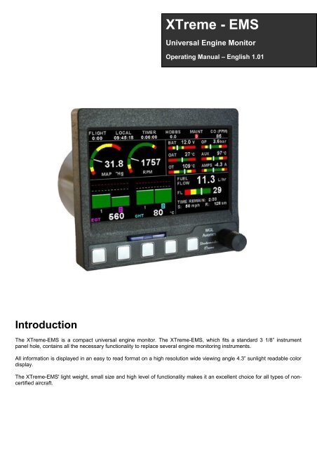
<strong>XTreme</strong> - <strong>EMS</strong><br />
Universal Engine Monitor<br />
Operating <strong>Manual</strong> – English 1.01<br />
Introduction<br />
The <strong>XTreme</strong>-<strong>EMS</strong> is a compact universal engine monitor. The <strong>XTreme</strong>-<strong>EMS</strong>, which fits a standard 3 1/8” instrument<br />
panel hole, contains all the necessary functionality to replace several engine monitoring instruments.<br />
All information is displayed in an easy to read format on a high resolution wide viewing angle 4.3” sunlight readable color<br />
display.<br />
The <strong>XTreme</strong>-<strong>EMS</strong>' light weight, small size and high level of functionality makes it an excellent choice for all types of noncertified<br />
aircraft.
<strong>XTreme</strong>-<strong>EMS</strong> Operating <strong>Manual</strong> Page 2<br />
1 Features<br />
Engine Monitoring:<br />
• 1x Engine RPM display<br />
• 1x Rotor RPM display<br />
• 1x Manifold pressure display<br />
• 1x Oil pressure display<br />
• 1x Oil temperature display<br />
• 2x Auxiliary analog channel displays (Pressure/Temperature/Current)<br />
• 12 Channel EGT/CHT display<br />
• 2x Fuel Flow display<br />
• 2x Fuel Level display<br />
• Special Rotax 912/914 engine monitor mode utilizing the standard built in Rotax NTC CHT probes<br />
• Programmable maintenance timer for scheduled routine engine maintenance<br />
• User settable Hobbs meter (password protected)<br />
• Fuel range / endurance calculated from GPS ground speed. *Note (3)<br />
• Supply Voltage display<br />
• OAT (Outside Air Temperature) display using an external OAT probe<br />
• Engine leaning feature<br />
• Stopwatch timer<br />
• Automatic / <strong>Manual</strong> flight timer<br />
• RTC (Real Time Clock)<br />
• Current monitor to measure charge/discharge currents. *Note (1)<br />
• CO Monitor. *Note (2)<br />
• Engine display screens are automatically configured to optimize screen space depending on what<br />
parameters are been displayed<br />
Hardware:<br />
• Powerful 32 bit ARM processor<br />
• 4.3” high resolution 480x272, sunlight readable, wide viewing angle, 600 nits TFT LCD display<br />
• LED backlight (brightness can be adjusted for low light flying conditions)<br />
• Fits standard 3 1/8” aircraft instrument panel hole<br />
• SD Card interface for data recording, user splash screens, checklists, graphic information pages, firmware<br />
upgrades etc<br />
• 1x RS232 communication port (CO Monitor *Note (2))<br />
• 1x <strong>MGL</strong> <strong>Avionics</strong> Airtalk communication port<br />
• 1x <strong>MGL</strong> <strong>Avionics</strong> RDAC communications port<br />
• 1x CAN communication port<br />
• Rotary control plus 5 independent buttons for easy menu navigation and user input<br />
• External alarm switch output for an external indicator lamp etc<br />
• Support for an external GPS receiver<br />
• Built in RTC (Real Time Clock)<br />
• Wide input supply voltage range of 8 to 30V DC<br />
• Built in voltage reversal and over voltage protection for harsh electrical environments<br />
• Light weight design
<strong>XTreme</strong>-<strong>EMS</strong> Operating <strong>Manual</strong> Page 3<br />
General:<br />
• Records maximum and minimum values of most displayed values<br />
• Built in black box recorder – records all engine data and GPS data to SD card. Data can be exported to<br />
Google Earth, Microsoft Excel, etc.<br />
• Includes a 1000 entry automatic flight log (Records start date&time, flight time, pilot number, Hobbs time<br />
and maintenance time)<br />
• User configurable start up (Splash) screen<br />
• Unlimited configurable checklists<br />
• Unlimited configurable graphic information displays<br />
• Automatic or manual local magnetic variation<br />
• Dual menu system for quick item selection and user setups<br />
• Sunrise/Sunset calculator<br />
• Firmware upgrades via SD Card<br />
• 1 year limited warranty<br />
(1) Requires optional <strong>MGL</strong> <strong>Avionics</strong> current monitor sensor<br />
(2) Requires optional CO Guardian CO detector<br />
(3) Requires external GPS receiver
<strong>XTreme</strong>-<strong>EMS</strong> Operating <strong>Manual</strong> Page 4<br />
2 <strong>XTreme</strong>-<strong>EMS</strong> Layout<br />
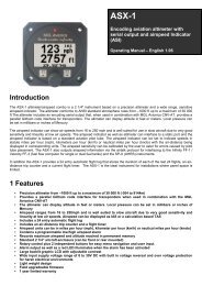
2.1 Front layout<br />
4.3” high resolution (480x272),<br />
sunlight readable, wide viewing<br />
angle, 600 nits LCD display<br />
SD card slot<br />
Rotary control. Press<br />
to access the quick<br />
select menus<br />
Press for previous<br />
display screen<br />
Soft keys<br />
Press to advance to the<br />
next display screen<br />
2.2 Rear layout<br />
Fits into a standard<br />
3 1/8” instrument<br />
Panel hole<br />
D15 Input connector<br />
(Power,Communications,<br />
OAT probe and alarm output )<br />
M4 Mounting Bolts
<strong>XTreme</strong>-<strong>EMS</strong> Operating <strong>Manual</strong> Page 5<br />
3 Display Screens<br />
Press the left or right most soft keys to cycle through the display screens.<br />
<strong>EMS</strong> DISPLAY<br />
GPS DISPLAY (External GPS receiver required)<br />
CHECKLIST/INFO DISPLAY
<strong>XTreme</strong>-<strong>EMS</strong> Operating <strong>Manual</strong> Page 6<br />
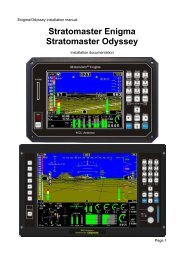
3.1 <strong>EMS</strong> Display<br />
3.1.1 Information bar<br />
FLIGHT:<br />
The flight time is automatically reset to zero when a new flight is started (manual or automatic flight detection). The “:” will<br />
flash when a flight is active. The flight timer can be started in the quick select menu (<strong>Manual</strong> flight mode).<br />
LOCAL:<br />
Local time normally includes an offset from Zulu time. The time offset can be setup in the “TIMERS SETUP” menu.<br />
TIMER:<br />
The Timer can be configured in the quick select menu.<br />
HOBBS:<br />
The <strong>XTreme</strong>-<strong>EMS</strong> contains a password protected Hobbs timer. The Hobbs time can be set to the current known engine<br />
time in the “TIMERS SETUP” menu. The Hobbs timer will only increment when the RPM is greater then the “HOBBS<br />
MINIMUM RPM”.<br />
MAINT (Maintenance Timer):<br />
This timer is set in engine hours and it will count down to zero when the engine RPM is greater then the “HOBBS<br />
MINIMUM RPM” value as set in the “TIMERS SETUP”. A good use for this function is to set the hours until your next<br />
spark plug change or engine inspection.<br />
The purpose of this function is to assist you in determining remaining hours until maintenance will be required. It is not<br />
intended as a replacement for the aircraft's maintenance log. It is therefore important that the aircraft's maintenance log<br />
be maintained in the normal manner. You should further use your own discretion in performing maintenance earlier than<br />
indicated should any aircraft performance problems arise.
<strong>XTreme</strong>-<strong>EMS</strong> Operating <strong>Manual</strong> Page 7<br />
A maximum of 999 hours can be entered as a maintenance interval. A<br />
reminder message will appear on startup when zero hours are<br />
remaining. The reminder message will automatically disappear after 10<br />
seconds or if the pilot presses any key. Engine running time for the<br />
purpose of the maintenance timer is defined as the run time where the engine RPM is greater than the “HOBBS<br />
MINIMUM RPM” value as set in the “TIMERS SETUP”.<br />
CO (PPM):<br />
This value is the carbon monoxide PPM value from the CO Monitor Detector (CO Guardian detector required).<br />
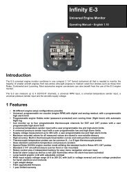
3.1.2 RPM / Rotor / MAP display section<br />
The RPM/Rotor/MAP section will maximize the space according to which parameter RPM/Rotor/MAP is enabled. The<br />
RPM,Rotor and MAP parameters can be configured in the “<strong>EMS</strong> SETUP” menu.<br />
RPM,Rotor and MAP enabled.<br />
RPM and MAP enabled.<br />
RPM only enabled<br />
MAP only enabled<br />
3.1.3 Volts, OAT, Oil Temperature/Pressure, Current and Auxiliary Analog section<br />
This section displays the supply voltage, OAT, oil temperature, oil pressure, as<br />
well as the 2 auxiliary analog channels. The oil temperature/pressure as well as<br />
the 2 auxiliary analog channels can be configured in the “<strong>EMS</strong> SETUP” menu.
<strong>XTreme</strong>-<strong>EMS</strong> Operating <strong>Manual</strong> Page 8<br />
3.1.4 Fuel display section<br />
The <strong>XTreme</strong>-<strong>EMS</strong> supports dual fuel flow and dual fuel levels. The fuel section will automatically try and maximize the<br />
display area according to the fuel parameters selected. The <strong>XTreme</strong>-<strong>EMS</strong> has 20 different fuel modes of operation. The<br />
fuel parameters can be configured in the “FUEL SETUP” menu.<br />
3.1.4.1 Single fuel flow and calculated tank level (single tank)<br />
Single fuel flow and fuel level sender (single tank)<br />
Differential fuel flow and calculated tank level (single tank)<br />
Differential fuel flow and fuel level sender (single tank)<br />
Summed fuel flow and calculated tank level (single tank)<br />
Summed fuel flow and fuel level sender (single tank)<br />
3.1.4.2 Dual fuel flow and calculated tank levels (dual tank)<br />
Dual fuel flow and dual fuel level senders (dual tank)<br />
3.1.4.3 Single fuel flow and dual fuel level senders (dual tank)<br />
Single fuel flow, single fuel level sender, single calculated tank<br />
Differential fuel flow and dual fuel level senders (dual tank)<br />
Differential flow, single fuel level sender, single calculated tank<br />
Summed fuel flow and dual fuel level senders (dual tank)<br />
Summed fuel flow, single fuel level sender, single calculated tank
<strong>XTreme</strong>-<strong>EMS</strong> Operating <strong>Manual</strong> Page 9<br />
3.1.4.4 Single/Differential/Summed fuel flow, single fuel level sender, single calculated tank<br />
These modes are nice for multiple fuel tanks whereby one or more tanks are difficult to insert level senders in. Potential<br />
problems such as those listed below can easily be diagnosed by doing side by side comparisons between a calculated<br />
and physical tank.<br />
• Leaks in the fuel system<br />
• Uneven drain of interconnected tanks<br />
• Malfunction of the level sender<br />
• Malfunction of the flow sender<br />
3.1.4.5 Single fuel flow only indicator<br />
This mode is displayed if either fuel flow 1 or fuel flow 2 is selected and no fuel level senders are selected.<br />
3.1.4.6 Dual fuel flow indicator<br />
This mode is displayed if both fuel flow 1 and fuel flow 2 is selected and the fuel mode is selected for dual flow. Both fuel<br />
level senders are disabled.<br />
3.1.4.7 Single tank level indicator<br />
This mode is displayed if either fuel level 1 or fuel level 2 is selected. Both fuel flow senders are disabled.
<strong>XTreme</strong>-<strong>EMS</strong> Operating <strong>Manual</strong> Page 10<br />
3.1.4.8 Dual tank level indicator<br />
This mode is displayed if both fuel level 1 and fuel level 2 is selected. Both fuel flow senders are disabled.<br />
3.1.4.9 Differential/Summed fuel flow<br />
This mode is displayed if both fuel flow 1 and fuel flow 2 is selected and the fuel mode is selected for either differential<br />
or summed.<br />
3.1.4.10 Calculated Fuel Tanks<br />
Calculated fuel tanks will have the text “CALC” in the fuel bar to indicate that the fuel level is calculated from fuel flow and<br />
that it is not a physical measure of the fuel tank.<br />
3.1.4.11 Speed, Range and GPS Fix Status<br />
The speed value will change color depending on the source of the information:<br />
White: The <strong>XTreme</strong>-<strong>EMS</strong> is using the cruising speed for the range calculation<br />
Magenta: The <strong>XTreme</strong>-<strong>EMS</strong> is using the GPS ground speed for the range calculation<br />
Cyan: The <strong>XTreme</strong>-<strong>EMS</strong> is using the airtalk airspeed for the range calculation
<strong>XTreme</strong>-<strong>EMS</strong> Operating <strong>Manual</strong> Page 11<br />
3.1.5 EGT/CHT display section<br />
The <strong>XTreme</strong> supports up to 12 thermocouples for EGTs/CHTs. The EGT/CHT section will automatically try and maximize<br />
the display area according to the number of EGTs/CHTs selected. The EGT/CHT parameters can be configured in the<br />
“EGT SETUP” and “CHT SETUP” menu.<br />
The EGT/CHT number will highlight to the indicated the temperature value if “HIGHEST” is selected. The EGT highlight<br />
color is magenta, and the CHT color is cyan.<br />
High Alarm<br />
Maximum temperature<br />
reached indicator<br />
High Caution<br />
EGT group indicator<br />
Temperature unit<br />
Indicates highest value if<br />
“HIGHEST” is selected or<br />
the highlighted bar value<br />
if “SCANNING” is selected<br />
CHT group indicator
<strong>XTreme</strong>-<strong>EMS</strong> Operating <strong>Manual</strong> Page 12<br />
3.2 <strong>EMS</strong> Quick Select Menu System<br />
Press the rotary control when the <strong>EMS</strong> screen is displayed to access the <strong>EMS</strong> quick select<br />
menu.<br />
START FLIGHT:<br />
Select this option to manually start/stop a flight. This menu option is only shown if the <strong>XTreme</strong>-<strong>EMS</strong> is setup to select the<br />
manual flight option under the “FLIGHT LOG” setup menu. The ':' will flash to indicate that a valid flight is in progress.<br />
FUEL REFILL:<br />
Select this menu option to refill a calculated fuel tank.<br />
Press the “FULL” soft key for a quick fill to the full<br />
reading in the tank setup menu. Press the “EXIT”<br />
soft key when done.<br />
CRUISE SPEED:<br />
Select this menu option to enter your average cruising<br />
speed. If there is no GPS fix or no airtalk airspeed data<br />
available then the Xtreme-<strong>EMS</strong> will use the average<br />
cruising speed to calculate fuel range. It is advisable to<br />
enter your average cruising speed irrespective if you are<br />
using an external GPS receiver or external airtalk<br />
airspeed device. If the GPS signal is lost during flight<br />
then the Xtreme-<strong>EMS</strong> automatically defaults to this<br />
value.
<strong>XTreme</strong>-<strong>EMS</strong> Operating <strong>Manual</strong> Page 13<br />
LEAN MODE:<br />
EGT information is also very useful for fuel mixture control. As the fuel mixture is leaned, so the exhaust gasses get<br />
hotter. This rise in temperature is a sign of increased combustion efficiency as the optimum mixture setting is approached.<br />
If the leaning progresses past a certain point however, the temperature will begin to drop. This temperature drop is the<br />
result of reduced energy output from the diminished fuel flow. The best operating mixture for aircraft engines is in the<br />
vicinity of this peak EGT reading. The <strong>XTreme</strong>-<strong>EMS</strong> has a special Leaning mode, which easily identifies the peak EGT<br />
condition allowing you to adjust your fuel mixture for best performance. Fuel mixture should be adjusted once you have<br />
decided on a suitable cruise power setting (typically 70%). Once leaning mode has been enabled, the "LEAN MODE"<br />
label is displayed at the bottom left of the <strong>EMS</strong> display to clearly differentiate it from the normal operating mode. As the<br />
fuel mixture is slowly leaned past the point at which the temperature begins to drop (by more than 10°C/15°F), the<br />
absolute EGT temperatures will change to show the EGT reading relative to this peak. The sequential order as each<br />
cylinder peaks is also shown as numeric text under the cylinder. Leaning mode can be canceled by pressing the soft key<br />
to “OFF” or by changing the display screen.<br />
EGT Temperature<br />
while leaning<br />
EGT Reading relative<br />
to first peaked cylinder<br />
Lean mode indictor<br />
2nd cylinder to peak<br />
1st cylinder to peak<br />
CRUISE MODE:<br />
Once cruise mode has been enabled, the "CRUISE MODE" label is displayed at<br />
the bottom of the <strong>EMS</strong> display to clearly differentiate it from the normal operating<br />
mode. All EGT and CHT readings are immediately sampled as reference<br />
temperatures for the cruise. The display then shows EGT and CHT values<br />
relative to this reference temperature. Cruise mode can be canceled by pressing<br />
the soft key to “OFF”.<br />
FUEL TOTALS:<br />
Select this menu option to display the fuel totals. Press<br />
the “RESET” soft key to reset the totalisers to zero.<br />
Press the “EXIT” soft key when done.
<strong>XTreme</strong>-<strong>EMS</strong> Operating <strong>Manual</strong> Page 14<br />
TIMER:<br />
Select this menu option to configure the timer. Use the<br />
rotary control to adjust the timers reset value. Press the<br />
“UP/DOWN” soft key to select whether the timer must<br />
count up or down, the “START/STOP” soft key to<br />
start or stop the timer and the “ON/OFF” soft key to<br />
enable or disable the timer.<br />
MIN/MAX:<br />
Select this menu option to display the maximum and<br />
minimum captured values. Press the “RESET” soft key<br />
to reset the min/max values to the current values.<br />
BACKLIGHT:<br />
Select this menu option to adjust the backlight brightness level. This may be desirable<br />
during low light flying conditions. Use the rotary control to adjust the brightness level.<br />
MENU:<br />
Select this menu option to enter the main menu system.
<strong>XTreme</strong>-<strong>EMS</strong> Operating <strong>Manual</strong> Page 15<br />
3.3 GPS Display (External GPS receiver required)<br />
The GPS page show the GPS information in an easy to read format. Sunrise/sunset times as well as the magnetic<br />
variation is shown.<br />
3.4 GPS Quick Select Menu System<br />
Press the rotary control when the GPS screen is shown to access the GPS quick select menu.<br />
BACKLIGHT:<br />
Select this menu option to adjust the backlight brightness level. This may be desirable<br />
during low light flying conditions. Use the rotary control to adjust the brightness level.<br />
MENU:<br />
Select this menu option to enter the main menu system.
<strong>XTreme</strong>-<strong>EMS</strong> Operating <strong>Manual</strong> Page 16<br />
3.5 Information/Checklist Display<br />
The Information/Checklist page shows checklists and graphic information pages which are loadable from the SD card.<br />
3.5.1 Graphic information pages<br />
The graphic information page allows you to display any type of image on the <strong>XTreme</strong>s high resolution graphics display.<br />
Creating your own graphic information pages<br />
You will need:<br />
·A bitmap picture of your choice (*.BMP, 480x272 pixel resolution)<br />
·The Enigma BMP to MIF converter tool (can be downloaded free of charge from http://www.mglavionics.co.za or can be<br />
found on the <strong>XTreme</strong>-<strong>EMS</strong> distribution SD card).<br />
The Enigma BMP to MIF program is used to convert images in Windows BMP format to Enigma MIF format. You can use<br />
this program to make your own startup screen (Splash screen) and graphic information pages. The color depth is limited<br />
to Enigmas 256 colors.<br />
Run the Enigma BMP image to MIF format converter program.<br />
Load an image file (and remember the location), select the resolution as width (480) and height (272) and press the<br />
process button. The new MIF image will be located in the same directory as the source (.BMP) file. Copy the created file<br />
(.MIF extension) to the Infopage directory on the SD card.<br />
The graphic information file can then be loaded by pressing the rotary<br />
control and selecting “INFO PAGES”. A window containing all the files<br />
with the .MIF extension is shown. Select the desired information page.<br />
The number of information pages that can be stored and displayed<br />
depends on the size of the SD card.
<strong>XTreme</strong>-<strong>EMS</strong> Operating <strong>Manual</strong> Page 17<br />
3.5.2 Checklists<br />
A checklist file is simply a text file created in a word processing program and saved with a .ECL extension. The name of<br />
the file does not matter but we suggest calling it something familiar so you can easily identify it. The length of each text<br />
line must not be more then 60 characters and must be terminated with an Enter (CR). The line will automatically be<br />
truncated at the end of the right hand side of the screen. Each checklist file must not be more then 30 lines.<br />
Copy the created file (.ECL extension) to the checklst directory on the<br />
SD card when you are complete. The checklist file can be loaded by<br />
pressing the rotary control and selecting “CHECKLISTS”. A window<br />
containing all the files with the .ECL extension will shown. Select the<br />
checklist you require. The number of checklists that can be stored and<br />
displayed depends on the size of the SD card.<br />
3.6 Information/Checklist Quick Select Menu System<br />
Press the rotary control when the Info/Checklist screen is shown to access the Info/checklist<br />
quick select menu.<br />
INFO PAGES:<br />
This menu option selects a graphic information page to display. A window will open displaying all the files with the .MIF<br />
extension in the Infopage directory on the SD card. Press the rotary control over the file you wish to load as a graphic<br />
information page.<br />
CHECKLISTS:<br />
This menu option selects a checklist to display. A window will open displaying all the files with the .XCL extension in the<br />
Checklst directory on the SD card. Press the rotary control over the file you wish to load as a checklist.<br />
BACKLIGHT:<br />
Select this menu option to adjust the backlight brightness level. This may be desirable<br />
during low light flying conditions. Use the rotary control to adjust the brightness level.<br />
MENU:<br />
Select this menu option to enter the main menu system.
<strong>XTreme</strong>-<strong>EMS</strong> Operating <strong>Manual</strong> Page 18<br />
4 Main Menu System<br />
To access the main menu system, press the rotary control knob, scroll down to the “MENU”<br />
option and press the rotary control knob again. Use the rotary control to navigate through the<br />
menu system.<br />
4.1 Menu Sub-Bar<br />
Use the menu sub-bar for quick menu navigation. Select the soft key directly under the text to activate that function.
<strong>XTreme</strong>-<strong>EMS</strong> Operating <strong>Manual</strong> Page 19<br />
4.2 Flight Log<br />
NOTE: The Flight log is stored in RAM until a valid flight has been completed. If the power is turned off to the<br />
<strong>XTreme</strong>-<strong>EMS</strong> before the flight has ended then the flight information will be lost.<br />
EXPORT FLIGHT LOG TO SD CARD (.CSV FILE):<br />
Use this function to export the current flight logs stored in the <strong>XTreme</strong>-<strong>EMS</strong> to a SD card. The exported filename is called<br />
XTFLIGHT.CSV. The exported flight log is exported in a CSV (Comma Separated Variable) file format and can be<br />
imported into programs such as Microsoft Excel and Open Office.<br />
VIEW FLIGHT LOG:<br />
This allows the pilot to view the last 1000 recorded flights.<br />
ERASE FLIGHT LOG:<br />
Use this function to erase the current flight log stored in the <strong>XTreme</strong>-<strong>EMS</strong>.<br />
PILOT NUMBER:<br />
Select a pilot number under which the next flights will be logged. Every flight entry in the flight log has a pilot number<br />
associated to it.<br />
FLIGHT DETECT:<br />
Select if you want the flight log to automatically “AUTOMATIC” start or if you want to manually “MANUAL” start and stop<br />
it.
<strong>XTreme</strong>-<strong>EMS</strong> Operating <strong>Manual</strong> Page 20<br />
The <strong>XTreme</strong> uses the following algorithm to determine if a flight is in progress (“AUTOMATIC” mode): If the ground speed<br />
is greater than the preset “FLIGHT DETECT MIN GROUND SPEED” value or the RPM is greater than the preset<br />
“FLIGHT DETECT MINIMUM RPM” value for a duration of 60 seconds or more, a flight is started with a logbook entry.<br />
The flight ends if ground speed or RPM falls below the preset value for 30 seconds.<br />
The above algorithm ensures that touch-and-goes will not result in the end of a flight and a logbook entry.<br />
FLIGHT DETECT MINIMUM RPM: (Automatic mode only)<br />
Enter the minimum RPM threshold that will start a new flight log entry.<br />
FLIGHT DETECT MINIMUM GROUND SPEED: (Automatic mode only, External GPS Required)<br />
Enter the minimum ground speed threshold that will start a new flight log entry.
<strong>XTreme</strong>-<strong>EMS</strong> Operating <strong>Manual</strong> Page 21<br />
4.3 <strong>EMS</strong> Setup
<strong>XTreme</strong>-<strong>EMS</strong> Operating <strong>Manual</strong> Page 22<br />
4.3.1 RPM Setup<br />
RPM DISPLAY:<br />
Select if you want the RPM to be displayed in “RPM” or “PERCENT” .If you do not want any RPM information then set this<br />
parameter to "OFF". If the rotor RPM is set to "RPM" or "PERECENT" then the engine RPM display will automatically be<br />
enabled.<br />
RPM 100% DISPLAY:<br />
Select the maximum value that you want the RPM to correlate to 100%.<br />
RPM DISPLAY MAX:<br />
Select the maximum RPM that you want the RPM dial to show. This can give you increased display resolution.<br />
RPM DISPLAY MIN:<br />
Select the minimum RPM that you want the RPM dial to show. This can give you increased display resolution.<br />
HIGH ALARM:<br />
This enables or disables the RPM high alarm.<br />
HIGH ALARM:<br />
Enter the RPM threshold for when the high alarm must be activated. Any RPM value above this value will activate the<br />
alarm.<br />
HIGH CAUTION:<br />
Enter the RPM value for the high caution. This is the lower value of the upper yellow band.<br />
LOW CAUTION:<br />
Enter the RPM value for the low caution. This is the upper value of the lower yellow band.<br />
LOW ALARM:<br />
This enables or disables the RPM low alarm.<br />
LOW ALARM:<br />
Enter the RPM threshold for when the low alarm must be activated. Any RPM value below this value will activate the<br />
alarm.
<strong>XTreme</strong>-<strong>EMS</strong> Operating <strong>Manual</strong> Page 23<br />
PULSES/REV:<br />
Enter the number of pulses per RPM. For engines with an uneven number of cylinders like three cylinder four stroke<br />
engines you can enter values containing fractions (usually 1.5 in this example). Most four stroke engines would generate<br />
one pulse for every two revolutions per cylinder. A four cylinder automotive four stroke engine would thus generate 2<br />
pulses per revolution. A typical Rotax DCDI two stroke engine would generate 6 pulses per revolution. The well known<br />
Rotax 912/914 engine generates one pulse per revolution.<br />
RPM RESOLUTION:<br />
Select the step size between successive RPM values eg. if the RPM value is 4003 RPM and the “RPM RESOLUTION” is<br />
5 then the actual value shown is 4005 RPM.<br />
4.3.2 Rotor Setup<br />
ROTOR DISPLAY:<br />
Select if you want the rotor RPM to be displayed in “RPM” or “PERCENT” .If you do not want any rotor RPM information<br />
then set this parameter to off. If the rotor RPM is set to "RPM" or "PERECENT" then the engine RPM display will<br />
automatically be enabled.<br />
ROTOR 100% DISPLAY:<br />
Select the maximum value that you want the rotor RPM to correlate to 100%.<br />
HIGH ALARM:<br />
This enables or disables the Rotor RPM high alarm.<br />
HIGH ALARM:<br />
Enter the Rotor RPM threshold for when the high alarm must be activated. Any Rotor RPM value above this value will<br />
activate the alarm.<br />
HIGH CAUTION:<br />
Enter the Rotor RPM value for the high caution. This is the lower value of the upper yellow band.<br />
LOW CAUTION:<br />
Enter the Rotor RPM value for the low caution. This is the upper value of the lower yellow band.<br />
LOW ALARM:<br />
This enables or disables the Rotor low alarm.
<strong>XTreme</strong>-<strong>EMS</strong> Operating <strong>Manual</strong> Page 24<br />
LOW ALARM:<br />
Enter the Rotor RPM threshold for when the low alarm must be activated. Any Rotor RPM value below this value will<br />
activate the alarm.<br />
PULSES/REV:<br />
Enter the number of pulses per rotor RPM.<br />
ROTOR RESOLUTION:<br />
Select the step size between successive Rotor RPM values eg. if the Rotor RPM value is 403 RPM and the “ROTOR<br />
RESOLUTION” is 5 then the actual value shown is 405 RPM.
<strong>XTreme</strong>-<strong>EMS</strong> Operating <strong>Manual</strong> Page 25<br />
4.3.3 EGT/CHT Setup<br />
EGT/CHT CHANNELS:<br />
Select the number of EGT or CHT channels you want to use. Choices are from 1 to 12. The temperature display will<br />
configure itself to make best possible use of the available display size. Please note that the minimum number of EGT &<br />
CHT channels that can be displayed is 1 and the maximum number of EGT and CHT channels that can be displayed is<br />
12.<br />
EGT/CHT DISPLAY MAX:<br />
Select the maximum temperature that you want the EGT/CHT bargraph to show. This can give you increased display<br />
resolution.<br />
EGT/CHT DISPLAY MIN:<br />
Select the minimum temperature that you want the EGT/CHT bargraph to show. This can give you increased display<br />
resolution.<br />
HIGH ALARM:<br />
This enables or disables the EGT/CHT high alarm.<br />
HIGH ALARM:<br />
Enter the temperature threshold for when the high alarm must be activated. Any temperature above this value will activate<br />
the alarm.<br />
HIGH CAUTION:<br />
Enter the temperature value for the high caution.
<strong>XTreme</strong>-<strong>EMS</strong> Operating <strong>Manual</strong> Page 26<br />
PROBE:<br />
Select if you are using a K-type, J-type or E-type thermocouple probe for the EGT/CHT group. All probes supplied by<br />
<strong>MGL</strong> <strong>Avionics</strong> are K-Type. J-types are sometimes used with American made CHT probes. All EGT probes are K-type. E-<br />
type probes are seldom used.<br />
TEMPERATURE UNIT:<br />
Select whether you want the EGT/CHT temperature to be displayed in degrees Celsius (ºC) or degrees Fahrenheit (ºF).<br />
MODE:<br />
A selection between “HIGHEST” or “SCANNING” can be selected. If “HIGHEST“ is selected then the current highest<br />
thermocouple temperature is displayed. If “SCANNING” is selected then the unit will cycle through each thermocouple at<br />
the time specified in “SCAN TIME”.<br />
SCAN TIME:<br />
Specify the time that each of the channels must be displayed for. This menu option is only shown if “SCANNING” is<br />
selected for the display mode.<br />
4.3.3.1 Special Rotax 912/914 probe mode<br />
In this mode the RDAC AUX 3 and AUX 4 analog input channels become the Rotax CHT channel 1 and CHT channel 2<br />
respectively. All CHT setups must still be done under the “CHT SETUP” menu. The sender selection for the “AUX 3” and<br />
“AUX 4” must be set for “OFF”. A probe type of “NTC” must be selected for the probe setting in the “CHT SETUP” menu.<br />
The reason for using the NTC inputs is that the sensors Rotax use are standard NTC temperature probes and not of a<br />
thermocouple type.
<strong>XTreme</strong>-<strong>EMS</strong> Operating <strong>Manual</strong> Page 27<br />
4.3.4 Fuel Setup<br />
UNIT:<br />
Select your desired units for distance and fuel quantity. The following options are available:<br />
L/sm: Liters and statute miles<br />
G/sm: U.S. Gallons and statute miles<br />
L/nm: Liters and nautical miles<br />
G/nm: U.S. Gallons and nautical miles<br />
L/km: Liters and kilometer<br />
G/km: U.S. Gallons and kilometers<br />
SPEED:<br />
Select which speed will be used for fuel range/endurance based calulations. You can select beteween "AIRTALK-<br />
AIRSPEED" which can be transmitted from an external airspeed indicator such as the <strong>MGL</strong> <strong>Avionics</strong> ASI-1/3 or "GPS-<br />
GROUND SPEED". If a 2D or 3D GPS is not obtained and "GPS-GROUND SPEED" is selected then the <strong>XTreme</strong>-<strong>EMS</strong><br />
will default to use the cruising speed for the fuel range/endurance calculations.<br />
FLOW 1/2:<br />
This enables or disables the Flow 1/2 display on the EFIS and MFD displays.<br />
KFACTOR 1/2:<br />
The K-Factor is the number of pulses generated by the fuel flow sender for one liter of fuel. The dual range fuel flow<br />
sender supplied by <strong>MGL</strong> <strong>Avionics</strong> has a K-Factor of 7000 in the low flow mode (jet installed) and 1330 for the high flow<br />
mode (no jet installed). The Flowscan 201A-6 has a K-Factor of 8454. You can use the K-Factor to calibrate your fuel flow<br />
sender. See the RDAC manual for more details on how to calibrate and install the fuel flow sender.<br />
MODE:<br />
Select if you want to measure fuel flow using a fuel flow sender or by using fuel injectors.<br />
FLOW MODE:<br />
If both fuel flow senders are selected then select if they are operating on individual fuel tanks (dual) or if they are<br />
operating in a supply/return type fuel system (differential).<br />
TANK 1/2 SETUP:<br />
Select this menu item to setup the fuel level for fuel tank 1/2. See below for more details.
<strong>XTreme</strong>-<strong>EMS</strong> Operating <strong>Manual</strong> Page 28<br />
Fuel level setup. (Only tank 1 setup is shown, follow the same steps for tank 2 setup)<br />
TANK 1/2:<br />
Select if the fuel tank has a physical fuel level sender connected to it or if the Xtreme must use a calculation based virtual<br />
fuel tank. If you do not want any fuel level information then set this parameter to off.<br />
TANK SIZE:<br />
Enter the size of the fuel tank in your system. It is recommended to choose a size that is slightly less than the actual size<br />
so you can compensate for sender inaccuracies and give you a measure of reserve fuel.<br />
LOW ALARM:<br />
This enables or disables the fuel level low alarm.<br />
LOW ALARM:<br />
Enter your desired minimum fuel value that you would like to trigger the fuel low alarm.<br />
LOW CAUTION:<br />
Enter the fuel level value for the low fuel caution.<br />
CALIBRATE TANK:<br />
The fuel level sender needs to be calibrated before it can be used with this system. The calibration allows the system to<br />
learn the shape of your tank as well as any errors your fuel level sender or installation has.<br />
Regardless of your use of a fuel flow sender, you can install a fuel level sender into your fuel tank. These level senders<br />
are inexpensive and are available as after market replacement fittings from a car spares outlet. We recommend the<br />
senders available from VDO.<br />
Be aware that some makes of cheap level senders can prove troublesome, as the lever arms tend to be sticky. This<br />
prevents the floats from floating on the surface of the fuel at all times. As a consequence, this will lead to incorrect fuel<br />
level indication.
<strong>XTreme</strong>-<strong>EMS</strong> Operating <strong>Manual</strong> Page 29<br />
Adjusting calibration points automatically<br />
Select “SENDER” for the “MODE” menu item. Once you have installed a fuel level sender into your tank, make sure the<br />
float can travel all the way from empty to full position without hindrance of any kind. The calibration procedure should be<br />
carried out with your aircraft in flight attitude. This means you need to lift the tail if you have a tail-dragger or lift the nose<br />
wheel if you have a weightshift trike.<br />
Calibration procedure<br />
• Start the calibration procedure with an empty tank.<br />
• Add five liters of fuel (our reserve quantity) using a suitable measure. Make sure the measure is suitably<br />
accurate. This is now the “level sender reading at 0 Lt” position. Move the highlight to this position and wait until<br />
the sender reading has stabilized (You will see the sender reading at the top line). This could take up to a minute<br />
so have patience.<br />
ENSURE THAT THE FLOAT IS NOT SUBMERGED AND IS FLOATING ON TOP OF THE FUEL LEVEL.<br />
Should this number not react to changes of your level sender position, then you have a problem. Please check<br />
your wiring according to the installation section of this manual. You should expect the number to change in the<br />
region of at least 20 to 60 counts per calibration position. If the number does not change with fuel level or only<br />
changes a very small amount – check your installation. Something is not right!<br />
• If you see the number changing then everything is well. Once it has stabilized and the highlight is on the 0 L<br />
position, press the rotary control to transfer the reading from the sender to the calibration point.<br />
• Now you are ready for the next step. Add the required amount of fuel to get to the next level (In our case 9 Lt –<br />
this is 20% tank capacity). Once done, wait for the reading to stabilize and press the rotary control again after you<br />
have moved the highlight to the “9 L” position.<br />
• Proceed in a similar manner until you have reached the last calibration position at 100% tank capacity.<br />
You are done!<br />
To finish your calibration, exit the calibration function by moving the highlight over the “- - -PREVIOUS MENU - -<br />
-” menu item and press the rotary control.<br />
The instrument uses the 6 calibration points to work out a correction curve that takes into account the tolerances of your<br />
fuel level sender and the shape of your fuel tank. This results in an incredibly accurate and usable fuel level display that<br />
far exceeds that available from ordinary dial type gauges.
<strong>XTreme</strong>-<strong>EMS</strong> Operating <strong>Manual</strong> Page 30<br />
Adjusting calibration points manually<br />
You may want to set individual calibration points manually. For example you may find that your fuel level is over<br />
reading at a specific fuel level. Correcting the tank level reading for this area can be simply done by adjusting the<br />
calibration point. You can do this by moving the float level with your hands to the desired position and then performing the<br />
calibration as outlined above, or you can use the manual option.<br />
Select “MANUAL” for the “MODE” menu item. Then highlight the point you want to change manually and press the rotary<br />
control. Use the rotary control to adjust the value. Press the rotary control when done.<br />
Note: The calibration positions may be edited by using the rotary control. This allows you, in theory, to copy calibration<br />
settings from one instrument to another. We however recommend that you do go though the calibration procedure even if<br />
the two aircraft are identical in all respects. Tolerances do exist and the calibration cancels these out. Accurate fuel level<br />
displays are a vital safety factor for an aircraft and a very useful feature for peace of mind during cross county flights.<br />
Notes on Slope error<br />
Sender value is a value determined by the <strong>XTreme</strong>. It<br />
is used to calculate fuel level, fuel endurance<br />
estimate and current range estimate. The fuel tank<br />
setup sender value can either increase in value as<br />
fuel is added or decrease in value if fuel is added.<br />
This is dependent on the type of fuel level sender<br />
used. However should the second reading be larger<br />
than the first reading all readings will have to be<br />
larger than the previous readings. Likewise should<br />
the second reading be smaller than the first reading<br />
all readings will have to be smaller than the<br />
previous reading.<br />
If this is not the case the wording "SLOPE ERROR" will be displayed. This could happen when fuel was removed instead<br />
of added between steps, no fuel was added between steps or when the fuel level sender was moved in the wrong<br />
direction e.g. moving the fuel level sender manually when it is not inserted in to the fuel tank. Determine the cause of the<br />
error if you should get a slope error message. If you do not know the cause of your error it is best to start from scratch. It<br />
should be remembered that accuracy in the fuel tank calibration is extremely important to enable your <strong>XTreme</strong> to display<br />
the correct data.<br />
TANK FILTER:<br />
Select the damping factor for the fuel level. A selection of "NONE", "LOW", "MED" or "HIGH" can be made.
<strong>XTreme</strong>-<strong>EMS</strong> Operating <strong>Manual</strong> Page 31<br />
4.3.5 Manifold Setup<br />
MAP DISPLAY:<br />
This enables or disables the manifold pressure display on the <strong>EMS</strong> displays screens<br />
MAP UNIT:<br />
Select if you want the manifold pressure displayed in mB (millibars) or “Hg (inches of mercury).<br />
MAP DISPLAY MAX:<br />
Select the maximum pressure that you want the manifold bargraph in the <strong>EMS</strong> displays to show. This can give you<br />
increased display resolution.<br />
MAP DISPLAY MIN:<br />
Select the minimum pressure that you want the manifold bargraph in the <strong>EMS</strong> display to show. This can give you<br />
increased display resolution.<br />
HIGH ALARM:<br />
This enables or disables the manifold pressure high alarm.<br />
HIGH ALARM:<br />
Enter the pressure threshold for when the high alarm must be activated. Any pressure above this value will activate the<br />
alarm.<br />
HIGH CAUTION:<br />
Enter the pressure value for the high caution. This is the lower value of the upper yellow band.<br />
LOW CAUTION:<br />
Enter the pressure value for the low caution. This is the upper value of the lower yellow band.<br />
LOW ALARM:<br />
This enables or disables the manifold pressure low alarm.<br />
LOW ALARM:<br />
Enter the pressure threshold for when the low alarm must be activated. Any pressure below this value will activate the<br />
alarm.
<strong>XTreme</strong>-<strong>EMS</strong> Operating <strong>Manual</strong> Page 32<br />
FILTER:<br />
This function can be used to select the signal filter time constant. Selections are "NONE", “FAST” or “SLOW”. This<br />
selection influences the rate at which your manifold pressure can change its reading.<br />
MAP CALIBRATION FACTOR:<br />
The sender in the RDAC is shipped uncalibrated. To calibrate the manifold pressure, compare and adjust the calibration<br />
factor until the manifold reading is the same as the pressure value in brackets. The pressure value in brackets is the<br />
barometer reading built into the Xtreme. The manifold pressure can only be calibrated in mB.
<strong>XTreme</strong>-<strong>EMS</strong> Operating <strong>Manual</strong> Page 33<br />
4.3.6 Oil Temperature Setup<br />
OIL TEMPERATURE DISPLAY:<br />
This enables or disables the oil temperature display on the <strong>EMS</strong> displays screens<br />
SENDER:<br />
Select what type of sender you are using. Select “VDO” for a VDO resistive sender, “WESTACH” for Westach thermistor<br />
type senders, “<strong>MGL</strong>” for a <strong>MGL</strong> NTC resistive temperature sender, “LM335” for a <strong>MGL</strong> precision temperature sender or<br />
“USER” for a custom sender. The <strong>XTreme</strong> has a built in linearization curve for a standard 50ºC to 150ºC VDO resistive<br />
sender, Westach senders and the <strong>MGL</strong> NTC resistive sender.<br />
If the sender type is set to “USER"<br />
CALIBRATE SENDER:<br />
If the sender type is set to “USER”, then use this menu option to calibrate your temperature sender. See section 4.4.9 for<br />
more information.<br />
If the sender type is set to “LM335"<br />
LM335:<br />
If the sender type is set to LM335, then use this menu option to calibrate your LM335 precision temperature sender. If<br />
recalibration is required then adjust the value using the rotary control until the temperature matches the reference ambient<br />
temperature. Please note that the LM335 can only be calibrated in degrees Celsius irrespective if the <strong>XTreme</strong> is setup to<br />
display temperature in Fahrenheit.<br />
Menu options for all sender types<br />
TEMPERATURE UNIT:<br />
Select whether you want the temperature to be displayed in degrees Celsius (ºC) or in degrees Fahrenheit (ºF).<br />
DISPLAY MAX:<br />
Select the maximum temperature that you want the oil temperature bargraph to show. This can give you increased<br />
display resolution.
<strong>XTreme</strong>-<strong>EMS</strong> Operating <strong>Manual</strong> Page 34<br />
DISPLAY MIN:<br />
Select the minimum temperature that you want the oil temperature bargraph to show. This can give you increased display<br />
resolution.<br />
LOW ALARM:<br />
This enables or disables the oil temperature low alarm.<br />
LOW ALARM:<br />
Enter the temperature threshold for when the low alarm must be activated. Any temperature below this value will activate<br />
the alarm.<br />
LOW CAUTION:<br />
Enter the temperature value for the low caution. This is the upper value of the lower yellow band.<br />
HIGH CAUTION:<br />
Enter the temperature value for the high caution. This is the lower value of the upper yellow band.<br />
HIGH ALARM:<br />
This enables or disables the temperature high alarm.<br />
HIGH ALARM:<br />
Enter the temperature threshold for when the high alarm must be activated. Any temperature above this value will activate<br />
the alarm.
<strong>XTreme</strong>-<strong>EMS</strong> Operating <strong>Manual</strong> Page 35<br />
4.3.7 Oil Pressure Setup<br />
OIL PRESSURE DISPLAY:<br />
This enables or disables the oil pressure display on the <strong>EMS</strong> displays screens<br />
TYPE:<br />
Select if you are using a resistive, 4-20mA or 0-5V output pressure sender.<br />
If the “RESISTIVE” pressure sender is selected<br />
SENDER:<br />
Select what type of resistive pressure sender you are using. Select “VDO” for VDO / resistive senders, “USER” for a<br />
custom sender.<br />
MODEL:<br />
Select which VDO pressure sender you are using. A selection between a VDO 2, 5 or 10 Bar can be selected.<br />
If the “0-5V” pressure sender is selected<br />
SENDER:<br />
Select the type of 0-5V sender used. Select “UMA” for UMA senders of “USER” for a custom 0-5V sender.<br />
MODEL:<br />
For UMA senders select the UMA model number.<br />
If the “4-20mA” pressure sender is selected<br />
SENDER:<br />
Select the type of 4-20mA sender used. Select “ROTAX” for Rotax 912/914 4-20mA sender or “USER” for a custom 4-<br />
20mA sender.<br />
PRESSURE @ 4mA:<br />
Enter the pressure specified at 4mA output.
<strong>XTreme</strong>-<strong>EMS</strong> Operating <strong>Manual</strong> Page 36<br />
PRESSURE @ 20mA:<br />
Enter the pressure specified at 20mA output.<br />
If the “USER" pressure sender is selected<br />
CALIBRATE SENDER:<br />
If the sender type is set to “USER”, then use this menu option to calibrate your pressure sender. See section 4.4.9 for<br />
more information.<br />
Menu options for all sender types<br />
PRESSURE UNIT:<br />
Select whether you want to display the pressure in Bar, PSI or PSI(0.1). The PSI(0.1) is for low range pressure senders<br />
e.g. UMA 7PSI.<br />
DISPLAY MAX:<br />
Select the maximum pressure that you want the oil pressure bargraph to show. This can give you increased display<br />
resolution.<br />
DISPLAY MIN:<br />
Select the minimum pressure that you want the oil pressure bargraph to . This can give you increased display resolution.<br />
LOW ALARM:<br />
This enables or disables the pressure low alarm.<br />
LOW ALARM:<br />
Enter the pressure threshold for when the low alarm must be activated. Any pressure below this value will activate the<br />
alarm.<br />
LOW CAUTION:<br />
Enter the pressure value for the low caution. This is the upper value of the lower yellow band.<br />
HIGH CAUTION:<br />
Enter the pressure value for the high caution. This is the lower value of the upper yellow band.<br />
HIGH ALARM:<br />
This enables or disables the manifold pressure high alarm.<br />
HIGH ALARM:<br />
Enter the pressure threshold for when the high alarm must be activated. Any pressure above this value will activate the<br />
alarm.
<strong>XTreme</strong>-<strong>EMS</strong> Operating <strong>Manual</strong> Page 37<br />
4.3.8 Auxiliary analog 3/4 Setup<br />
The analog AUX3/4 channel on the RDAC is a general purpose channel that can be used for pressure as well as for<br />
temperature senders.<br />
FUNCTION:<br />
Select the function for the analog channel. Options are “PRESSURE”, “TEMPERATURE”, “CURRENT” or “OFF”.<br />
If the “PRESSURE” function is selected:<br />
TYPE:<br />
Select if you are using a resistive, 4-20mA or 0-5V output pressure sender.<br />
If the “RESISTIVE” pressure sender is selected<br />
SENDER:<br />
Select what type of resistive pressure sender you are using. Select “VDO” for VDO / resistive senders, “USER” for a<br />
custom sender.<br />
MODEL:<br />
Select which VDO pressure sender you are using. A selection between a VDO 2, 5 or 10 Bar can be selected.<br />
If the “0-5V” pressure sender is selected<br />
SENDER:<br />
Select the type of 0-5V sender used. Select “UMA” for UMA senders of “USER” for a custom 0-5V sender.
<strong>XTreme</strong>-<strong>EMS</strong> Operating <strong>Manual</strong> Page 38<br />
MODEL:<br />
For UMA senders select the UMA model number.<br />
If the “0-20mA” pressure sender is selected<br />
SENDER:<br />
Select the type of 4-20mA sender used. Select “ROTAX” for Rotax 912/914 4-20mA sender or “USER” for a custom 4-<br />
20mA sender.<br />
PRESSURE @ 4mA:<br />
Enter the pressure specified at 4mA output.<br />
PRESSURE @ 20mA:<br />
Enter the pressure specified at 20mA output.<br />
If the “USER" pressure sender is selected<br />
SENDER:<br />
Select the type of 4-20mA sender used. Select “ROTAX” for Rotax 912/914 4-20mA sender or “USER” for a custom 4-<br />
20mA sender.<br />
CALIBRATE SENDER:<br />
If the sender type is set to “USER”, then use this menu option to calibrate your pressure sender. See section 4.4.9 for<br />
more information.<br />
Menu options for all sender types<br />
LABEL:<br />
Choose one of a selection of labels to suit your pressure input so you can identify it easily.<br />
PRESSURE UNIT:<br />
Select whether you want to display the pressure in Bar, PSI or PSI(0.1). The PSI(0.1) is for low range pressure senders<br />
e.g. UMA 7PSI.<br />
DISPLAY MAX:<br />
Select the maximum pressure that you want the bargraph to show. This can give you increased display resolution.<br />
DISPLAY MIN:<br />
Select the minimum pressure that you want the bargraph to show. This can give you increased display resolution.<br />
LOW ALARM:<br />
This enables or disables the pressure low alarm.<br />
LOW ALARM:<br />
Enter the pressure threshold for when the low alarm must be activated. Any pressure below this value will activate the<br />
alarm.
<strong>XTreme</strong>-<strong>EMS</strong> Operating <strong>Manual</strong> Page 39<br />
LOW CAUTION:<br />
Enter the pressure value for the low caution. This is the upper value of the lower yellow band.<br />
HIGH CAUTION:<br />
Enter the pressure value for the high caution. This is the lower value of the upper yellow band.<br />
HIGH ALARM:<br />
This enables or disables the manifold pressure high alarm.<br />
HIGH ALARM:<br />
Enter the pressure threshold for when the high alarm must be activated. Any pressure above this value will activate the<br />
alarm.<br />
If the “TEMPERATURE” function is selected:<br />
SENDER:<br />
Select what type of sender you are using. Select “VDO” for a VDO resistive sender, “WESTACH” for Westach thermistor<br />
type senders, “<strong>MGL</strong>” for a <strong>MGL</strong> NTC resistive temperature sender, “LM335” for a <strong>MGL</strong> precision temperature sender or<br />
“USER” for a custom sender. The <strong>XTreme</strong> has a built in linearization curve for a standard 50ºC to 150ºC VDO resistive<br />
sender, Westach senders and the <strong>MGL</strong> NTC resistive sender.<br />
If the sender type is set to “USER"<br />
CALIBRATE SENDER:<br />
If the sender type is set to “USER”, then use this menu option to calibrate your pressure sender. See section 4.4.9 for<br />
more information.<br />
If the sender type is set to “LM335"<br />
LM335:<br />
If the sender type is set to LM335, then use this menu option to calibrate your LM335 precision temperature sender. If<br />
recalibration is required then adjust the value using the rotary control until the temperature matches the reference ambient<br />
temperature. Please note that the LM335 can only be calibrated in degrees Celsius irrespective if the <strong>XTreme</strong> is setup to<br />
display temperature in Fahrenheit.
<strong>XTreme</strong>-<strong>EMS</strong> Operating <strong>Manual</strong> Page 40<br />
Menu options for all sender types<br />
LABEL:<br />
Choose one of a selection of labels to suit your temperature input so you can identify it easily.<br />
TEMPERATURE UNIT:<br />
Select whether you want the temperature to be displayed in degrees Celcius (ºC) or in degrees Fahrenheit (ºF).<br />
DISPLAY MAX:<br />
Select the maximum temperature that you want the bargraph to show. This can give you increased display resolution.<br />
DISPLAY MIN:<br />
Select the minimum temperature that you want the bargraph to show. This can give you increased display resolution.<br />
LOW ALARM:<br />
This enables or disables the temperature low alarm.<br />
LOW ALARM:<br />
Enter the temperature threshold for when the low alarm must be activated. Any temperature below this value will activate<br />
the alarm.<br />
LOW CAUTION:<br />
Enter the temperature value for the low caution. This is the upper value of the lower yellow band.<br />
HIGH CAUTION:<br />
Enter the temperature value for the high caution. This is the lower value of the upper yellow band.<br />
HIGH ALARM:<br />
This enables or disables the temperature high alarm.<br />
HIGH ALARM:<br />
Enter the temperature threshold for when the high alarm must be activated. Any temperature above this value will activate<br />
the alarm.<br />
4.3.9 Calibrating the user defined pressure and Temperature Senders<br />
1. Enter the number of points that you want to<br />
calibrate.<br />
2. Enter the display reading that you want to<br />
show when the sender is at that actual display<br />
reading.<br />
3. Enter the ADC (analog to digital converter)<br />
reading that corresponds to this display reading.<br />
The ADC reading is shown at the bottom of the<br />
display if you are applying the actual<br />
stimulus from the temperature or pressure<br />
sender. You can also manually enter this value<br />
if the ADC value is known or pre-calculated.<br />
4. Continue entering display and ADC values<br />
until all the points have been entered.<br />
5. Verify the above calibration by checking the<br />
temperature/pressure display versus the actual<br />
applied sender stimulus.
<strong>XTreme</strong>-<strong>EMS</strong> Operating <strong>Manual</strong> Page 41<br />
If the “CURRENT” function is selected:<br />
DISPLAY MAX:<br />
Select the maximum current that you want the bargraph to show. This can give you increased display resolution.<br />
DISPLAY MIN:<br />
Select the minimum current that you want the bargraph to show. This can give you increased display resolution.<br />
LOW ALARM:<br />
This enables or disables the current low alarm.<br />
LOW ALARM:<br />
Enter the current threshold for when the low alarm must be activated. Any current below this value will activate the alarm.<br />
LOW CAUTION:<br />
Enter the current value for the low caution. This is the upper value of the lower yellow band.<br />
HIGH CAUTION:<br />
Enter the current value for the high caution. This is the lower value of the upper yellow band.<br />
HIGH ALARM:<br />
This enables or disables the current high alarm.<br />
HIGH ALARM:<br />
Enter the current threshold for when the high alarm must be activated. Any current above this value will activate the<br />
alarm.<br />
ZERO CURRENT SENSOR:<br />
Select this function to indicate to the <strong>XTreme</strong> that zero current is flowing through the <strong>MGL</strong> current monitor. This is best<br />
done with the <strong>MGL</strong> current monitor disconnected from the main current suppling conductor.<br />
CURRENT SPAN CALIBRATION:<br />
Enter the maximum value that your <strong>MGL</strong> current monitor can measure. This will depend on the distance and the method<br />
that is used to attach the <strong>MGL</strong> current monitor to the main current suppling conductor. It will be best if a multimeter can be<br />
inserted in series with the current supplying conductor and the span calibration adjusted until the <strong>XTreme</strong> matches that of<br />
the multimeter. Please see the <strong>MGL</strong> current monitor document for more information.
<strong>XTreme</strong>-<strong>EMS</strong> Operating <strong>Manual</strong> Page 42<br />
4.3.10 Volts Setup<br />
VOLTS DISPLAY MAX:<br />
Select the maximum value that you want the volts bargraph in the <strong>EMS</strong> display to show. This can give you increased<br />
display resolution.<br />
VOLTS DISPLAY MIN:<br />
Select the minimum value that you want the volts bargraph in the <strong>EMS</strong> display to show. This can give you increased<br />
display resolution.<br />
HIGH ALARM:<br />
This enables or disables the volts high alarm.<br />
HIGH ALARM:<br />
Enter the voltage threshold for when the high alarm must be activated. Any voltage above this value will activate the<br />
alarm.<br />
HIGH CAUTION:<br />
Enter the voltage for the high caution. This is the lower value of the upper yellow band.<br />
LOW CAUTION:<br />
Enter the voltage for the low caution. This is the upper value of the lower yellow band.<br />
LOW ALARM:<br />
This enables or disables the volts low alarm.<br />
LOW ALARM:<br />
Enter the voltage threshold for when the low alarm must be activated. Any voltage below this value will activate the alarm.<br />
VOLTS CALIBRATION FACTOR:<br />
Measure the battery voltage with a multimeter and then adjust this value to match that of the multimeters volts reading.
<strong>XTreme</strong>-<strong>EMS</strong> Operating <strong>Manual</strong> Page 43<br />
4.3.11 OAT Setup<br />
OAT TEMPERATURE UNIT:<br />
Select whether you want the OAT to be displayed in degrees Celsius (ºC) or in degrees Fahrenheit (ºF).<br />
OAT DISPLAY MAX:<br />
Select the maximum temperature that you want the OAT bargraph in the <strong>EMS</strong> display to show. This can give you<br />
increased display resolution.<br />
OAT DISPLAY MIN:<br />
Select the minimum temperature that you want the OAT bargraph in the <strong>EMS</strong> display to show. This can give you<br />
increased display resolution.<br />
HIGH ALARM:<br />
This enables or disables the OAT high alarm.<br />
HIGH ALARM:<br />
Enter the temperature threshold for when the high alarm must be activated. Any temperature above this value will activate<br />
the alarm.<br />
HIGH CAUTION:<br />
Enter the temperature for the high caution. This is the lower value of the upper yellow band.<br />
LOW CAUTION:<br />
Enter the temperature for the low caution. This is the upper value of the lower yellow band.<br />
LOW ALARM:<br />
This enables or disables the OAT low alarm.<br />
LOW ALARM:<br />
Enter the temperature threshold for when the low alarm must be activated. Any temperature below this value will activate<br />
the alarm.<br />
OAT CALIBRATION FACTOR:<br />
During the factory calibration a factor has been determined and entered here that will give you an accurate OAT reading.<br />
If you find this value is incorrect then adjust the calibration factor until the <strong>XTreme</strong>s OAT matches that of a precision<br />
thermometer. Calibration can only be done in Celcius (ºC).
<strong>XTreme</strong>-<strong>EMS</strong> Operating <strong>Manual</strong> Page 44<br />
4.3.12 CO Monitor Carbon Monoxide Setup<br />
The CO Monitor Carbon Monoxide menu option allows the pilot to enable the CO Guardians Carbon Monoxide detector.<br />
The <strong>XTreme</strong>-<strong>EMS</strong> will display the carbon monoxide value on the <strong>EMS</strong> display as well as enable the carbon monoxide<br />
warning alarm. Please see the relevant CO Guardian detector manuals for more information.<br />
CO Monitor:<br />
Select which CO Monitor you are using. Select “None” to disable the CO display.<br />
RESET CO GUARDIAN:<br />
This will reset the CO Guardian Carbon Monoxide detector, perform a self test and then will re-enable the CO Guardian<br />
Carbon Monoxide detector.
<strong>XTreme</strong>-<strong>EMS</strong> Operating <strong>Manual</strong> Page 45<br />
4.4 GPS Setup<br />
GPS:<br />
Select “OFF” to disable the GPS information screen or select "EXTERNAL" if you have an external NMEA compatible<br />
GPS connected to the <strong>XTreme</strong>-<strong>EMS</strong>.<br />
If an external GPS is used then it must output the following NMEA sentences<br />
• GGA - Global positioning system fix data<br />
• RMC – Recommended minimum specific GNSS data<br />
• GSA – GNSS DOP and active satellites<br />
• GSV – GNSS satellites in view<br />
NMEA stands for the National Marine Electronics Association. For more information please visit www.nmea.org.<br />
GPS BAUD RATE:<br />
Select the baud rate to match the external GPS receiver you are using.<br />
POSITION FORMAT:<br />
Select the display format of the GPS latitude and longitude.<br />
ALTITUDE UNIT:<br />
Select the unit of the altitude display.<br />
COG:<br />
Select if you want the COG to be related to true or magnetic north.<br />
LOCAL VARIATION:<br />
Select “AUTO” to allow the <strong>XTreme</strong>-<strong>EMS</strong> to automatically calculate the local variation or “MANUAL” for manual local<br />
variation input.<br />
AUTO LOCAL VARIATION:<br />
This item displays the calculated local magnetic variation. The <strong>XTreme</strong>-<strong>EMS</strong> will calculate the local variation every 10<br />
minutes if a valid 2D or 3D GPS fix is obtained.<br />
MANUAL LOCAL VARIATION:<br />
This item allows the pilot to manually enter his local variation.
<strong>XTreme</strong>-<strong>EMS</strong> Operating <strong>Manual</strong> Page 46<br />
4.5 Timers Setup<br />
HOBBS MINIMUM RPM:<br />
Enter the RPM limit in which the Hobbs timer/Maintenance timer must start incrementing.<br />
SET HOBBS TIME:<br />
This function allows you to set the engine Hobbs<br />
meter to any value. Typically, you would use this<br />
function to set the Hobbs meter to the current<br />
known engine time. Use the rotary control to<br />
change the value. Press the rotary control to<br />
accept and exit the menu option. If the Hobbs<br />
code is set to another value beside zero, then the<br />
pilot will be prompted to enter the Hobbs access<br />
code before allowing him to change the Hobbs time.<br />
This feature is useful for charted and flying school<br />
planes.<br />
CHANGE HOBBS CODE:<br />
This menu option allows you to change the Hobbs access code. You will first be prompted to enter the current code<br />
followed by entering in a new code followed by re-entering the new code. If the new code and the re-entered code is the<br />
same, then the Hobbs access code will be changed. Default code is 0000.
<strong>XTreme</strong>-<strong>EMS</strong> Operating <strong>Manual</strong> Page 47<br />
SET MAINTENANCE TIMER:<br />
These timers allow you to keep track of engine<br />
maintenance interval. Set the timer when you have<br />
serviced your engine. A typical time might be 50<br />
hours. This function allows you to set an engine<br />
maintenance timer. This timer is set in engine hours<br />
and it will count down to zero when the engine RPM<br />
is greater then the “HOBBS MINIMUM RPM”. A<br />
good use for this function is to set the hours until<br />
your next spark plug change or engine inspection.<br />
Use the rotary control to change the value.<br />
UTC OFFSET:<br />
Enter the UTC offset for your location. The UTC offset can be adjust in half an hour increments.<br />
RTC SOURCE:<br />
Select if you want the RTC UTC time to come from the GPS receiver or the internal RTC. Both real time clocks are<br />
powered by an internal 3V lithium coin cell battery. The internal battery can be replaced by unscrewing the 5 screws<br />
holding the back and front enclosures together as well as the 2 screws next to the D15 connector. Delicately slide out the<br />
electronics and replace the battery. The battery is a CR2032 coin cell.<br />
SET UTC DATE & TIME:<br />
Use the rotary control to set the UTC date & time in<br />
the internal RTC.
<strong>XTreme</strong>-<strong>EMS</strong> Operating <strong>Manual</strong> Page 48<br />
4.6 Data Recording Setup<br />
The <strong>XTreme</strong>-<strong>EMS</strong> has the ability to act as a black box recorder recording flight data directly onto an inserted SD card for<br />
later playback and investigation using the <strong>MGL</strong> <strong>Avionics</strong> Black Box viewer program. See the Black box viewer documents<br />
for further information. The Black box viewer can also convert the data into other file formats such as:<br />
• KML: Keyhole Markup Language / Google Earth<br />
• CSV: Comma-Separated Variable<br />
• IGC: FAI Gliding commission<br />
The <strong>XTreme</strong>-<strong>EMS</strong> records the engine data as well as the GPS data (If an external GPS receiver is available) once per<br />
second WHEN A VALID FLIGHT IS DETECTED (AUTOMATIC OR MANUAL FLIGHT DETECT MODE).<br />
CREATE RECORDING FILE ON SD CARD:<br />
Selecting this menu option will create a file on the SD card (If inserted and not write protected) called enigma.rec with a<br />
fixed file size of 10MB. The reason behind the fixed file size of the recording file has to do with limited write cycles of the<br />
SD card and the instability of the MS-DOS file system. With a fixed file size, the <strong>XTreme</strong>-<strong>EMS</strong> never has to write to either<br />
the directory structure or FAT tables of the SD card eliminating wear of the card or possible data corruption. Once the<br />
recording file has been filled, the recording continues at the start of the file again, overwriting the oldest data in the file.<br />
The file size is large enough to record 5-20 hours of data depending on what data is recorded.<br />
DATA RECORDING ON:<br />
Selecting “ON” will enable the data recording functionality.
<strong>XTreme</strong>-<strong>EMS</strong> Operating <strong>Manual</strong> Page 49<br />
4.6.1 Examples of the exported flight data using CSV format and the KML format
<strong>XTreme</strong>-<strong>EMS</strong> Operating <strong>Manual</strong> Page 50<br />
4.7 Miscellaneous Setup<br />
AIRCRAFT REGISTRATION:<br />
Enter your aircraft registration. A maximum of 8<br />
characters can be entered. The aircraft registration is<br />
displayed on the start up (Splash) screen.<br />
SAVE SETTINGS TO SD CARD:<br />
Select this option to save all the <strong>XTreme</strong>-<strong>EMS</strong> settings to the SD card. This is useful when setting up the instrument on<br />
the PC simulator and then later transferring the settings on the instrument itself. A file called “XTREME.<strong>EMS</strong>” will be<br />
created in the root directory of the SD card.<br />
RECALL SETTINGS FROM SD CARD:<br />
Select this option to recall all the <strong>XTreme</strong>-<strong>EMS</strong> settings from the SD card. This is useful when setting up the instrument<br />
on the PC simulator and then later transferring the settings to the instrument itself. The settings will be loaded from a file<br />
called “XTREME.<strong>EMS</strong>” in the root directory of the SD card.
<strong>XTreme</strong>-<strong>EMS</strong> Operating <strong>Manual</strong> Page 51<br />
4.8 ADC Values<br />
These values are mainly used for debugging purposes. Contact the <strong>MGL</strong> factory or your local dealer for more information.<br />
5 Startup (Splash) Screen<br />
Creating your own Startup (Splash) Screen<br />
You will need:<br />
·A bitmap picture of your choice (*.BMP, 480x272 pixel resolution)<br />
·The Enigma BMP to MIF converter tool (can be downloaded free of charge from http://www.mglavionics.co.za or can be<br />
found on the <strong>XTreme</strong> SD card).<br />
The Enigma BMP to MIF program is used to convert images in Windows BMP format to Enigma MIF format. You can use<br />
this program to make your own startup screen (Splash screen) and graphic information display screens. The color depth<br />
is limited to Enigmas 256 colors.<br />
Run the Enigma BMP image to MIF format converter program.<br />
Load an image file (and remember the location), select the resolution as width(480) and height (272) and press the<br />
process button. The new MIF image will be located in the same directory as the source (BMP) file.<br />
If the original file was not named Splash.BMP, rename the new *.MIF file to Splash.MIF, and copy the Splash.MIF file into<br />
the root directory of your SD card.<br />
The picture will be displayed when the unit is powered up.
<strong>XTreme</strong>-<strong>EMS</strong> Operating <strong>Manual</strong> Page 52<br />
6 Loading factory default settings<br />
Press and hold the left and right most soft keys simultaneously on power up to load default factory settings. The following<br />
message will be displayed:<br />
7 Alarm condition<br />
If an alarm condition occurs the following will happen:<br />
• The item causing the alarm condition will flash on the screen<br />
• An alarm warning message will be displayed on the screen<br />
• An external alarm switch will close<br />
The alarm warning message and switch closure will remain until any button is pressed or until the condition(s) that<br />
activated the alarm no longer exist.<br />
The alarm output can be used to switch an external alarm indicator. The external alarm switch is an open collector<br />
transistor switch to ground with a maximum rating of 0.5A DC. It is possible to wire the alarm contacts of several<br />
Stratomaster instruments in parallel should this be desired.<br />
To avoid false activation of the alarms, the alarm function is only active 10 seconds after the instrument has powered up.<br />
8 Cleaning<br />
The unit should not be cleaned with any abrasive substances. The screen is very sensitive to certain cleaning materials<br />
and should only be cleaned using a clean, damp cloth.<br />
Warning: The <strong>XTreme</strong>-<strong>EMS</strong> is not waterproof. Serious damage could occur if the unit is exposed<br />
to water and/or spray jets.
<strong>XTreme</strong>-<strong>EMS</strong> Operating <strong>Manual</strong> Page 53<br />
9 <strong>XTreme</strong>-<strong>EMS</strong> Specifications<br />
Operating Temperature Range -10ºC to 50ºC (14ºF to 122ºF)<br />
Storage Temperature Range -20ºC to 80ºC (-4ºF to 176ºF)<br />
Humidity<br />
<strong>XTreme</strong>-<strong>EMS</strong> Operating <strong>Manual</strong> Page 54<br />
10 Installation<br />
10.1 <strong>XTreme</strong>-<strong>EMS</strong> General Connection Diagram<br />
The use of an external 1A fuse is recommended. Connect the supply terminals to your aircraft’s power supply. The<br />
<strong>XTreme</strong>-<strong>EMS</strong> can be used on both 12V and 24V without the use of any pre-regulators. Ensure that the supply voltage will<br />
not drop below 8V during operation as this may result in incorrect readings.<br />
Please see <strong>MGL</strong> <strong>Avionics</strong> RDAC documentation for installation and usage.
<strong>XTreme</strong>-<strong>EMS</strong> Operating <strong>Manual</strong> Page 55<br />
10.2 Xtreme-<strong>EMS</strong> DB15 Cable connections<br />
D15 Male<br />
NC=Not Connected<br />
DB 15 Pin Color Function<br />
1 Red 8-30Vdc power<br />
2 White Alarm Output<br />
3,4,9,10 Black Ground<br />
5 NC RS232 Port 2 Transmit<br />
6 NC RS232 Port 2 Receive<br />
7 NC RS232 Port 1 Transmit<br />
8 NC RS232 Port 1 Receive<br />
11 Green OAT Probe<br />
12 NC CAN High<br />
13 NC CAN Low<br />
14 Blue RDAC Signal<br />
15 Purple Airtalk<br />
The <strong>XTreme</strong>-<strong>EMS</strong> has a D15 Female connector. The connecting cable must have a D15 male connector attached to it.<br />
11 Firmware upgrades<br />
The <strong>XTreme</strong>-<strong>EMS</strong>' firmware can be upgraded in the field to the latest version via the SD card. This will keep your<br />
<strong>XTreme</strong>-<strong>EMS</strong> up to date with bug fixes and new features.<br />
The name of the firmware file must be called XTREME.FW and it must reside in the root directory of the SD card. When<br />
the <strong>XTreme</strong>-<strong>EMS</strong> powers up it will first look at the SD card to see whether the file exists, if it does then it will prompt the<br />
user to upgrade the firmware. Use the soft keys at the bottom to select whether to upgrade to the new firmware or to exit<br />
the firmware upgrade feature. The <strong>XTreme</strong>-<strong>EMS</strong> also provides a soft key to delete the XTREME.FW file from the SD card<br />
to avoid removing the SD card and deleting it with a PC.<br />
If the file does not exist, then the firmware upgrade function is bypassed and the <strong>XTreme</strong>-<strong>EMS</strong>' main program is<br />
executed. Please check http://www.mglavionics.co.za/<strong>XTreme</strong>.html regularly for the latest firmware releases.
<strong>XTreme</strong>-<strong>EMS</strong> Operating <strong>Manual</strong> Page 56<br />
12 <strong>XTreme</strong>-<strong>EMS</strong> Dimensions<br />
12.1 Front view
<strong>XTreme</strong>-<strong>EMS</strong> Operating <strong>Manual</strong> Page 57<br />
12.2 Side view
<strong>XTreme</strong>-<strong>EMS</strong> Operating <strong>Manual</strong> Page 58<br />
12.3 Top view
<strong>XTreme</strong>-<strong>EMS</strong> Operating <strong>Manual</strong> Page 59<br />
13 Warranty<br />
This product carries a warranty for a period of one year from date of purchase against faulty workmanship or defective<br />
materials, provided there is no evidence that the unit has been mishandled or misused. Warranty is limited to the<br />
replacement of faulty components and includes the cost of labor. Shipping costs are for the account of the purchaser.<br />
Note: Product warranty excludes damages caused by unprotected, unsuitable or incorrectly wired<br />
electrical supplies and or sensors, and damage caused by inductive loads.<br />
14 Disclaimer<br />
Operation of this instrument is the sole responsibility of the purchaser of the unit. The user must make themselves familiar<br />
with the operation of this instrument and the effect of any possible failure or malfunction.<br />
This instrument is not certified by the FAA. Fitting of this instrument to certified aircraft is subject to the rules and<br />
conditions pertaining to such in your country. Please check with your local aviation authorities if in doubt. This instrument<br />
is intended for ultralight, microlight, home built and experimental aircraft. Operation of this instrument is the sole<br />
responsibility of the pilot in command (PIC) of the aircraft. This person must be proficient and carry a valid and relevant<br />
pilot’s license. This person has to make themselves familiar with the operation of this instrument and the effect of any<br />
possible failure or malfunction. Under no circumstances does the manufacturer condone usage of this instrument for IFR<br />
flights.<br />
The manufacturer reserves the right to alter any specification without notice.