Create successful ePaper yourself
Turn your PDF publications into a flip-book with our unique Google optimized e-Paper software.
<strong>DE2</strong>-<strong>70</strong> User Manual<br />
FPGA<br />
SOPC<br />
NIOS II<br />
Program<br />
JTAG<br />
Blaster<br />
Hardware<br />
NIOS II<br />
TIMER<br />
JTAG<br />
System Interconnect Fabric<br />
SDRAM<br />
Controller<br />
SDRAM<br />
Controller<br />
Avalon<br />
MM Slave<br />
VGA<br />
Controller<br />
Multi-Port<br />
SSRAM<br />
Controller<br />
VIDEO-In<br />
Controller<br />
SDRAM-U1<br />
SDRAM-U2<br />
VGA<br />
SSRAM<br />
VIDEO IN<br />
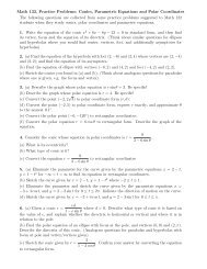
Figure 4.4. Video Capture Block Diagram.<br />
The control flow for video displaying is described below:<br />
1. Host computer downloads the raw image data to SDRAM-U2.<br />
2. Host issues a “display” command to Nios II processor.<br />
3. Nios II processor interprets the command received and moves the raw image data from<br />
the SDRAM to SSRAM through the Multi-Port SSRAM controller.<br />
4. VGA Controller continuously reads the raw image data from the SSRAM and sends them<br />
to the VGA port.<br />
The control flow for video capturing is described below:<br />
1. Host computer issues a “capture” command to Nios II processor.<br />
2. Nios II processor interprets the command and controls Video-In controller to capture the<br />
raw image data into the SSRAM. After capturing is done, Nios II processor copies the raw<br />
image data from the SSRAM to SDRAM-U2.<br />
3. Host computer reads the raw image data from the SDRAM-U2<br />
4. Host computer converts the raw image data to RGB color space and displays it.<br />
29