High Power Diode Lasers - Center for Biomedical Optics and New ...
High Power Diode Lasers - Center for Biomedical Optics and New ...
High Power Diode Lasers - Center for Biomedical Optics and New ...

Create successful ePaper yourself
Turn your PDF publications into a flip-book with our unique Google optimized e-Paper software.
Bio-Photonics ’03 Summer School<br />
<strong>High</strong> <strong>Power</strong> <strong>Diode</strong> <strong>Lasers</strong><br />
Fabrication<br />
Characterization<br />
Results in the near IR (732-980 nm)<br />
Applications<br />
Michel Krakowski<br />
Sophie-Charlotte Auzanneau<br />
Thales Research <strong>and</strong> Technology France
Fabrication<br />
•Materials<br />
• Epitaxy<br />
• Process<br />
Characterization<br />
Laser diodes<br />
• power <strong>and</strong> spectrum measurement<br />
• far-field <strong>and</strong> near-field measurement<br />
• The M² factor : definition, measurement<br />
• Saturation of the power : cause <strong>and</strong> solution = the large optical cavity<br />
Main epitaxial structures : at 808 nm, 940 nm, 980 nm <strong>and</strong> 732 nm<br />
Examples of lasers diodes<br />
• Ridge <strong>and</strong> broad-area lasers at 980 nm<br />
• high brigthness lasers near at 980 nm<br />
• state of the art<br />
• external approach : four-wave mixing<br />
• internal approach : the tapered laser diode<br />
• Tapered lasers bars at 980 nm coupled into an optical fiber<br />
• Laser diodes at 732 nm : broad-area laser results <strong>and</strong> aging test<br />
• Application to photodynamic therapy of laser diodes at 732 nm<br />
• Application to surgery <strong>and</strong> dentistry of laser diodes at 980 nm
How is a laser diode<br />
Max. size : 3 mm long<br />
<strong>and</strong> 100-200 µm large<br />
On Indium<br />
18 Au wires<br />
Laser<br />
6 mm<br />
Output<br />
facet<br />
Laser<br />
Alumina<br />
3 mm<br />
Copper holder
Schematic of a laser diode = stack of semiconductor materials<br />
layers<br />
Anti-reflection<br />
coating (AR 3%)<br />
100-200 µm<br />
<strong>High</strong><br />
reflection<br />
coating<br />
(HR 95%)<br />
2- 3mm<br />
Electrodes<br />
Confinement<br />
layers<br />
Separated<br />
confinement layers<br />
Cleaved facets<br />
Current injection<br />
Photon guiding<br />
Optical losses are<br />
reduced<br />
Mirrors<br />
Active region<br />
Lateral passivation<br />
Photon generating<br />
Electrical isolation
Which material system <strong>for</strong> which wavelength<br />
II-VI compounds<br />
<strong>Diode</strong> lasers<br />
GaN/AlInGaN<br />
GaAs/GaInAs/GaAlAs<br />
GaAs/GaInAsP<br />
InP/GaInAsP<br />
0<br />
0 0.5 1.0 1.5<br />
2.0<br />
Wavelength ( µm)<br />
GaSb/<br />
AlGaInSbAs<br />
Quantum Cascade lasers<br />
GaAs/AlGaAs<br />
GaInAs/AlInAs/InP<br />
THz <strong>and</strong><br />
mm wave<br />
0<br />
0 5 10 15 20<br />
Wavelength (<br />
µm)
Steps of the fabrication of a laser diode<br />
1- SUBSTRAT (wafer) 2- EPITAXY : growth of layers 3- LASER PROCESSING<br />
4- FACETS CLEAVING 5-chip cleaving<br />
6- MOUNTING, BONDING<br />
A 2’’ wafer ≈ 1000-2000 chips
substrate<br />
Schematic of the growth of semiconductor layers<br />
Dissociated<br />
molecules<br />
Dissociated<br />
molecules
Layers growth : 2 kinds of epitaxy<br />
MBE : Molecular Beam Epitaxy<br />
MOCVD : Metallo-Organic<br />
Chemical Vapor Deposition<br />
Molecules fluxes, with ≠ rates<br />
Gas fluxes, with ≠ rates<br />
Wafer en<br />
rotation<br />
400-500°<br />
Dissociated<br />
molecules<br />
Unused<br />
gas<br />
Rotating wafer ∼<br />
650°<br />
Liquid or solid sources<br />
Gas sources
Layers growth : 2 kinds of epitaxy<br />
MBE : Molecular Beam Epitaxy<br />
MOCVD : Metallo-Organic<br />
Chemical Vapor Deposition<br />
slow growth : good controle of the<br />
interfaces quality atomic layers.<br />
ultravacuum (10 -10 Torr)<br />
Controle in-situ of the thicknesses of the<br />
layers (diffraction X)<br />
A usual laser diode = 6h<br />
Quantum cascade laser diode = 40h<br />
Machines : Riber, Varian (en salle<br />
blanche)….<br />
No phosphide.<br />
faster growth : layers thicker 50-70 nm<br />
(no quantum cascade laser).<br />
under weak pressure or ambiant pressure.<br />
A usual laser diode = 5-6h<br />
Machines : Aixtron (white room)….<br />
phosphore allowed.<br />
organo-métallic = gas giving elements III<br />
( Triméthyl In, Ga, Al…)<br />
Arsine (As), phosphine (P), Silane (Si) :<br />
toxiques<br />
1 epitaxy machine = a small truck
Si 3 N 4 , SiO 2<br />
Process : why <br />
To define a surface where the current is injected<br />
Typical threshold current density of a laser diode J th<br />
~ 100 A/cm 2 to 1 kA/cm²<br />
To minimize it, we reduce the injection surface!<br />
Active region<br />
contact<br />
~<br />
Substrate<br />
~<br />
process<br />
~<br />
Substrate<br />
~<br />
EPITAXY<br />
size = 1 - 100<br />
mm<br />
Laser surface = 1 cm 2 I th = 100A to 1000 A !<br />
Laser surface = 100 µm x 1 mm = 10 -3 cm 2<br />
I th = 100 mA to 1 A
Process<br />
Three steps of the planar process<br />
Photolithography<br />
Masquage et<br />
Insolation UV<br />
Développement<br />
et ouverture<br />
Etching<br />
Ionic etching (dry etching)<br />
Chemical etching<br />
Coating<br />
(metallic <strong>and</strong> dielectric)
Then mounting on copper holder …<br />
p-down<br />
p-up<br />
N side<br />
xxxxxxxxx<br />
xxxxxxxxx<br />
P side<br />
xxxxxxxxx<br />
soldering<br />
xxxxxxxxx<br />
P side<br />
soldering<br />
N side<br />
current<br />
Thermal regulation (Peltier)<br />
current<br />
Thermal regulation (Peltier)<br />
The heat is well dissipated because<br />
the active region is near the<br />
thermal regulation<br />
For specific technologies<br />
high power laser diodes
And electrical wires soldering …<br />
Scale : the micron !!<br />
Now we can characterize the laser diode ... ha ha ha ...
Fabrication<br />
•Materials<br />
• Epitaxy<br />
• Process<br />
Characterization<br />
Laser diodes<br />
• power <strong>and</strong> spectrum measurement<br />
• far-field <strong>and</strong> near-field measurement<br />
• The M² factor : definition, measurement<br />
• Saturation of the power : cause <strong>and</strong> solution = the large optical cavity<br />
Main epitaxial structures : at 808 nm, 940 nm, 980 nm <strong>and</strong> 732 nm<br />
Examples of lasers diodes<br />
• Ridge <strong>and</strong> broad-area lasers at 980 nm<br />
• high brigthness lasers near at 980 nm<br />
• state of the art<br />
• external approach : four-wave mixing<br />
• internal approach : the tapered laser diode<br />
• Tapered lasers bars at 980 nm coupled into an optical fiber<br />
• Laser diodes at 732 nm : broad-area laser results <strong>and</strong> aging test<br />
• Application to photodynamic therapy of laser diodes at 732 nm<br />
• Application to surgery <strong>and</strong> dentistry of laser diodes at 980 nm
The laser diode : assymetric device elliptic<br />
beam<br />
Perpendicular (fast) axis<br />
Near-field (µm)<br />
∼ 1 µm<br />
<strong>Diode</strong> laser<br />
θ y<br />
cavité optique<br />
θ x<br />
HR<br />
AR<br />
Parallel (slow) axis<br />
Far-field<br />
(rad)<br />
We characterize<br />
according to each axis (no<br />
correlation)<br />
In the ⊥ direction, monomode<br />
beam. In the // direction, it’s<br />
different …
Polarization of a laser diode<br />
Point <strong>for</strong> electrical<br />
contact<br />
With a p-down laser<br />
diode :<br />
Pol. -<br />
Pol. +<br />
Thermal regulation
• power measurement : high divergence of the beam<br />
⇒ we use a sphere.<br />
z<br />
Laser diode<br />
Photodiode :<br />
power<br />
calculation<br />
Thermal<br />
regulation<br />
+<br />
spectrometer<br />
<strong>for</strong> λ
• Near-field measurement<br />
Microscope objective<br />
Laser diode<br />
CCD camera<br />
z<br />
Beam analyser<br />
Camera linked<br />
to a PC (beam<br />
analyser)
• far-field measurement<br />
Laser diode<br />
Diverging beam<br />
Rotating<br />
photodiode<br />
0.0<br />
-20<br />
power<br />
0.2 0.4 0.6 0.8 1.0<br />
θ<br />
z<br />
a<br />
n<br />
g<br />
l<br />
e<br />
-10<br />
0<br />
10<br />
θ 1/e²<br />
θ 1/2<br />
20<br />
θ
Brightness 3D (W.cm<br />
- 2<br />
.sr<br />
-1<br />
) =<br />
Luminance (brightness)<br />
emissive<br />
Optical<strong>Power</strong> (W)<br />
area (cm²) * solid<br />
angle<br />
(sr)<br />
Brightness<br />
1D<br />
-1 -1<br />
(W.cm .rad )<br />
=<br />
Perpendicular<br />
(fast) axis<br />
Optical<strong>Power</strong> (W)<br />
W (cm)* θ (rad)<br />
Near-<br />
field<br />
∝<br />
Optical<strong>Power</strong> (W)<br />
M<br />
²<br />
1D<br />
Laser diode<br />
θ y<br />
W x<br />
Optical cavity<br />
θ x<br />
Parallel (slow) axis<br />
Luminance ⇒ spatial beam quality ⇒ M² ⇒ near-field size <strong>and</strong> far-field<br />
angle of the beam.<br />
Far-<br />
field
W(z) =<br />
W<br />
W(z)<br />
0<br />
⎛<br />
1+<br />
⎜<br />
⎜<br />
⎝<br />
The Gaussian beam<br />
2<br />
⎞<br />
M2λ(z<br />
− z0)<br />
⎟<br />
2 ⎛ π ⎞<br />
M = ⎜ ⎟θ<br />
W > 1<br />
2 ⎟<br />
1/e² 01/e²<br />
πW0<br />
⎝ λ ⎠<br />
⎠<br />
0<br />
1<br />
Waist : 2 w 0<br />
z<br />
2θ<br />
1.0<br />
0.8<br />
0.6<br />
0.4<br />
0.2<br />
0.0<br />
-20 -10 0 1<br />
Taille u.a. 0<br />
W 0 1/e²<br />
2<br />
0<br />
Near-field at the waist -20 -10 0 10 20<br />
Ref. : A.E.Siegman, « <strong>New</strong> developments in laser resonators », SPIE Vol. 1224, 1990<br />
u.a.<br />
1.0<br />
0.8<br />
0.6<br />
0.4<br />
0.2<br />
0.0<br />
Divergence u.a.<br />
Far-field<br />
θ 1/e²
What is the limitation of the emitted power<br />
• <strong>Diode</strong> heating : power saturation , normally<br />
non-destructive (thermal roll-over)<br />
400<br />
350<br />
300<br />
250<br />
P (mW)<br />
200<br />
150<br />
100<br />
• Catastrophic optical mirror damage (COMD) :<br />
destructive<br />
50<br />
0<br />
0 200 400 600 800 1000<br />
I (mA)<br />
BC<br />
BV<br />
hν<br />
Recombinaison non-radiative<br />
électron-trou de surface<br />
Elévation de température<br />
Réabsorption optique<br />
COMD<br />
Face-miroir<br />
Filamentation
• Catastrophic optical mirror damage (COMD) : destructive<br />
Maximal emitted power:<br />
P<br />
MAX<br />
(mW /<br />
µm )<br />
= P ( λ)<br />
COMD<br />
1−R<br />
.<br />
1+<br />
R<br />
d<br />
Γ<br />
PCOMD: internal optical power density at threshold COMD<br />
R: mirror reflectivity<br />
d: active region thickness (reabsorbing)<br />
Γ: overlap of the transverse mode with the active region<br />
d : transverse spot size<br />
Γ<br />
Active-Region material P COMD (MW /cm 2 )<br />
InGaAs (0.92 - 0.98µm) 18-19<br />
InGaAsP (0.81µm) 18-19<br />
InAlGaAs (0.81µm) 13-14<br />
GaAs (0.81 - 0.87µm) 10-12<br />
Al 0.07 GaAs (0.81µm) 8-9<br />
Al 0.13 GaAs (0.78µm) 5<br />
(Botez, SPIE proceedings, vol. 3628, p5, 1999)<br />
To increase P max :<br />
>Structure design:<br />
- enlarged guides<br />
>Active region materials:<br />
-InAlGaAs<br />
- InGaAsP (Al-free)
Laser diode with an enlarged active region : advantages<br />
Wider transverse near-field (> 0.5 µm) : COMD level increased.<br />
Weak internal losses (< 1 cm -1 ):<br />
<strong>High</strong> external differential efficiency<br />
Longer cavity are possible (> 1 mm): thermal <strong>and</strong> electrical<br />
resistivities are decreased<br />
<strong>Power</strong> <strong>and</strong> efficiency record in CW<br />
Usual cavity<br />
(Thershold current minimized)<br />
1,0<br />
Enlarged cavity :<br />
Γclad => α<br />
Γqw => COMD<br />
Refractive index, Near field intensity<br />
p Cladding<br />
QW<br />
QW<br />
nid waveguide<br />
n Cladding<br />
Refractive index, Near field intensity<br />
0,8<br />
0,6<br />
0,4<br />
0,2<br />
0,0<br />
-0,2<br />
QW<br />
p Cladding<br />
nid Broad Waveguide<br />
n Cladding<br />
-4 -2 0 2 4<br />
Distance<br />
Distance
Fabrication<br />
•Materials<br />
• Epitaxy<br />
• Process<br />
Characterization<br />
Laser diodes<br />
• power <strong>and</strong> spectrum measurement<br />
• far-field <strong>and</strong> near-field measurement<br />
• The M² factor : definition, measurement<br />
• Saturation of the power : cause <strong>and</strong> solution = the large optical cavity<br />
Main epitaxial structures : at 808 nm, 940 nm, 980 nm <strong>and</strong> 732 nm<br />
Examples of lasers diodes<br />
• Ridge <strong>and</strong> broad-area lasers at 980 nm<br />
• high brigthness lasers near at 980 nm<br />
• state of the art<br />
• external approach : four-wave mixing<br />
• internal approach : the tapered laser diode<br />
• Tapered lasers bars at 980 nm coupled into an optical fiber<br />
• Laser diodes at 732 nm : broad-area laser results <strong>and</strong> aging test<br />
• Application to photodynamic therapy of laser diodes at 732 nm<br />
• Application to surgery <strong>and</strong> dentistry of laser diodes at 980 nm
Laser structure 732 nm :<br />
GaAsP / AlGaAs / AlGaAs<br />
• Tensile strained GaAsP QW<br />
TM polarisation<br />
• <strong>High</strong> Al – content<br />
of waveguide <strong>and</strong> cladding layers<br />
• LOC structure (1µm waveguide)
Fabrication<br />
•Materials<br />
• Epitaxy<br />
• Process<br />
Characterization<br />
Laser diodes<br />
• power <strong>and</strong> spectrum measurement<br />
• far-field <strong>and</strong> near-field measurement<br />
• The M² factor : definition, measurement<br />
• Saturation of the power : cause <strong>and</strong> solution = the large optical cavity<br />
Main epitaxial structures : at 808 nm, 940 nm, 980 nm <strong>and</strong> 732 nm<br />
Examples of lasers diodes<br />
• Ridge <strong>and</strong> broad-area lasers at 980 nm<br />
• high brigthness lasers near at 980 nm<br />
• state of the art<br />
• external approach : four-wave mixing<br />
• internal approach : the tapered laser diode<br />
• Tapered lasers bars at 980 nm coupled into an optical fiber<br />
• Laser diodes at 732 nm : broad-area laser results <strong>and</strong> aging test<br />
• Application to photodynamic therapy of laser diodes at 732 nm<br />
• Application to surgery <strong>and</strong> denistry of laser diodes at 980 nm
All the results presented here have been<br />
obtained in the IST-1999-10356 european<br />
project ULTRABRIGHT<br />
Reliable Ultra-Bright Laser <strong>Diode</strong> Sources<br />
For Terabit Telecommunications<br />
<strong>and</strong> Photodynamic Therapy Applications<br />
Results from :<br />
Thales Research <strong>and</strong> Technology (TRT)<br />
Thales Laser <strong>Diode</strong>s (TLD)<br />
Ceram Optec<br />
Ferdin<strong>and</strong>-Braun-Institut für Höchstfrequenztechnik<br />
R&T<br />
CeramOptec GmbH
Why a high brightness laser diode at 980 nm<br />
Laser with a GaInAs quantum well on GaAs<br />
substrate.<br />
Losses on the 1.55 µm signal in the optical fibers<br />
1.55 µm signal<br />
Erbium<br />
doped fiber<br />
pump<br />
Erbium<br />
Ion<br />
optical amplification with the EDFA<br />
(Erbium Doped Fiber Amplifier)
How can we bring more power in the optical<br />
fiber<br />
Efficient coupling of the emitted power in the optical fiber<br />
Pump diode<br />
Coupling optics<br />
Optical fiber<br />
⇒ that’s why we need : high power + high beam<br />
spatial quality<br />
= high brightness
12<br />
11<br />
10<br />
CW optical power records delivered by<br />
single 100µm wide emitters at 25°C<br />
30/06/00 13:35:35<br />
Max. optical power (W)<br />
9<br />
8<br />
7<br />
6<br />
5<br />
4<br />
3<br />
2<br />
(55 µm)<br />
GaAs/AlGaAs : Mitsui Chemicals, Jap.<br />
Al-free : Wisconsin U./ Coherent USA<br />
AlGaInAs/AlGaAs : Optopower Corp. USA<br />
AlGaAs : SDL, USA<br />
AlGaAs : Fraunhofer Inst., Ger.<br />
GaAsP/AlGaAs : F. Braun Inst., Ger.<br />
GaAs/AlGaAs : Thales TLD<br />
Al-free : Thales TRT<br />
720 740 760 780 800 820 840 860 880 900 920 940 960 980 1000<br />
Wavelength (nm)
In the perpendicular direction : quasi-gaussian<br />
far-field profile (M² close to 1) <strong>for</strong> all the<br />
lasers fabricated with the same epitaxy.<br />
1,0<br />
I (u.a.)<br />
0,5<br />
0,0<br />
-60 -30 0 30 60<br />
Angle (°)<br />
θ 1/e² ≈ 52-65°<br />
But in the parallel direction, it depends on the<br />
waveguide shape …
In the parallel direction : 2 main kinds of lasers<br />
The broad-area laser : high power (∼10W at 0.98µm) but low beam spatial quality<br />
100<br />
µm<br />
1.0<br />
2 mm Far field<br />
P = 1 W<br />
M² = 15-20<br />
I (u.a.)<br />
0.8<br />
0.6<br />
0.4<br />
0.2<br />
0.0<br />
-15 -10 -5 0 5 10 15<br />
Angle (°)<br />
8,7°<br />
9,8°<br />
in the //<br />
direction<br />
The ridge laser: high spatial beam quality but a few hundreds of mW<br />
5<br />
µm<br />
2 mm<br />
P =300 mW<br />
M² = 1.2<br />
I (u.a.)<br />
1.0<br />
0.8<br />
0.6<br />
0.4<br />
0.2<br />
0.0<br />
-15 -10 -5 0 5 10 15<br />
Angle (°)<br />
8°<br />
14°<br />
Far field<br />
in the //<br />
direction
The broad-area laser 100 µm large * 2mm long :<br />
The broad-area laser 0.98µm AR/HR 100 µm * 2mm:<br />
8.5W CW, (usually operating at 3-4 W)<br />
Threshold : 340mA (170 A/cm²)<br />
Efficiency : 0.95W/A<br />
Mondial Record : 10.6W CW (Botez, U Wisc.)<br />
I (u.a.)<br />
1,0<br />
0,8<br />
0,6<br />
0,4<br />
// Far-field<br />
at 1W<br />
//<br />
2.5<br />
10<br />
1.0<br />
0,2<br />
Voltage U /V<br />
2.0<br />
1.5<br />
1.0<br />
V<br />
P<br />
eff<br />
.<br />
9<br />
8<br />
7<br />
6<br />
5<br />
4<br />
3<br />
Optical <strong>Power</strong> P /W<br />
0.8<br />
0.6<br />
0.4<br />
Efficiency η<br />
C<br />
I (u.a.)<br />
0,0<br />
-15 -10 -5 0 5 10 15<br />
1,0<br />
0,8<br />
0,6<br />
0,4<br />
Angle (°)<br />
// Near-field<br />
at 1W<br />
//<br />
0.5<br />
2<br />
1<br />
0.2<br />
0,2<br />
0.0<br />
0<br />
0 2 4 6 8 1 0<br />
C u rre nt I /A<br />
0.0<br />
0,0<br />
0 40 80 120 160 200 240<br />
x (µm)<br />
At 1W , parallel M² > 15 …
The broad-area laser 100 µm large at 980 nm :<br />
reliability<br />
PROFIL DE VIEILLISSEMENT TGB 969 P= 1W I=1.4A à 30°C<br />
PUISSANCE OPTIQUE (W)<br />
1.60<br />
1.40<br />
1.20<br />
1.00<br />
0.80<br />
0.60<br />
0.40<br />
0.20<br />
0.00<br />
0 1000 2000 3000 4000 5000 6000 7000 8000 9000 10000 11000 12000 13000 14000 15000 16000<br />
TEMPS CUMULE (HEURES)<br />
1-4 1-6 1-7 1-8 1-9 2-5 2-7
The broad-area laser 100 µm large at 808 nm :<br />
reliability<br />
1.60<br />
PROFIL DE VIEILLISSEMENT TGB963D A 1W, 1,4 A, 40°C<br />
Puissance optique (W)<br />
1.40<br />
1.20<br />
1.00<br />
0.80<br />
0.60<br />
0.40<br />
0.20<br />
0.00<br />
0 1000 2000 3000 4000 5000 6000 7000 8000 9000 10000 11000 12000 13000 14000 15000 16000 17000 18000 19000 20000 21000 22000 23000<br />
Temps cumulé (heures)<br />
8-2 8-8 9-1 9-2 9-4
The ridge laser 5 µm large * 2mm long :<br />
1,0<br />
Laser ridge 0.98µm AR/HR 5µm * 2mm: 300 W<br />
CW, (usually operating at 100-300 mW)<br />
Threshold : 40mA<br />
Efficiency : 0.95W/A<br />
Record : 1.2W (with optimized mirrors treatments)<br />
I (u.a.)<br />
0,8<br />
0,6<br />
0,4<br />
0,2<br />
// Far-field<br />
at 300 mW<br />
//<br />
300<br />
250<br />
0,0<br />
-25 -20 -15 -10 -5 0 5 10 15 20 25<br />
angle (°)<br />
P (mW)<br />
200<br />
150<br />
100<br />
I (u.a.)<br />
1,0<br />
0,5<br />
//<br />
// Near-field<br />
at 300 mW<br />
50<br />
0<br />
0 50 100 150 200 250 300 350 400 450<br />
I (mA)<br />
0,0<br />
28 32 36 40 44<br />
x (µm)<br />
At 300 mW , parallel M² =1.2
Others solutions to improve the brightness (1) :<br />
internal approach<br />
MOPA<br />
1 mm<br />
Laser (straight section with a<br />
Bragg grating)<br />
R 2 =0.01%<br />
- 1.5W FWHM// 0.26° Ortel IEEE-<br />
PLT 99<br />
- Difficulties:<br />
•R 2 ≈ 0.01%<br />
• interaction between the 2 sections<br />
I 1 I 2<br />
Master Oscillator <strong>Power</strong> Amplifier<br />
Tapered amplifier<br />
section<br />
• p-down mounting is difficult<br />
α- DFB<br />
I<br />
- 0.94 W FWHM// 0.2° SDL<br />
CLEO-97<br />
- 14 éléments bar, 20 W 75 A,<br />
FWHM// 1.1° , SDL CLEO-97<br />
- weak wall-plug efficiency<br />
- difficult fabrication
Others solutions to improve the brightness (2) :<br />
internal approach<br />
The index guided tapered laser bar<br />
30 µm<br />
15 µm<br />
- 8W 10A, FWHM// 5° à 4.5W,<br />
R 2 =1%, GEC EL-99<br />
200 µm 1800 µm<br />
The gain guided tapered laser<br />
100 µm 1900 µm<br />
- 2.2 W 4 A FWHM// 0.24° M²=2.2, R2= 0.05%,<br />
θ 200 µm<br />
Fraunhofer SPIE-98<br />
- 25 lasers bar, 25W 50A, M²=2.6 / emitter,<br />
Ipol<br />
Monomode lateral section :<br />
ridge<br />
Fraunhofer IEEE-PTL99
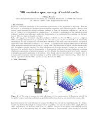
Others solutions to improve the brightness (3) :<br />
external approach<br />
Risø National Laboratory<br />
<strong>Optics</strong> & Fluid Dynamics Dept.<br />
Improving the Spatial <strong>and</strong> Temporal<br />
Coherence of <strong>High</strong>-<strong>Power</strong> <strong>Diode</strong> <strong>Lasers</strong><br />
Using Four-Wave Mixing in the Gain Material<br />
Paul M. Petersen<br />
<strong>Optics</strong> <strong>and</strong> Fluid Dynamics Department, Risø<br />
National Laboratory,<br />
DK-4000 Roskilde, Denmark<br />
P.M. Petersen et al.
Others solutions to improve the brightness (3) : external approach<br />
Risø National Laboratory<br />
<strong>Optics</strong> & Fluid Dynamics Dept.<br />
<strong>New</strong> Laser design at Risø National Laboratory<br />
Gain- <strong>and</strong> refractive index gratings in broad area laser<br />
diodes<br />
may be used <strong>for</strong> selective amplification of spatial modes<br />
The effect is based on spatial hole burning in the active<br />
semiconductor gain material.<br />
The third order nonlinear susceptibility <strong>and</strong> the mode<br />
suppressions factor depend on the angle between the<br />
interacting beams in the four-wave mixing.<br />
A narrow range of angles exist with strong gratings <strong>and</strong><br />
good mode suppression.<br />
P.M. Petersen et al.
Others solutions to improve the brightness (3) : external approach<br />
Risø National Laboratory<br />
<strong>Optics</strong> & Fluid Dynamics Dept.<br />
Gain- <strong>and</strong> refractive index gratings in laser diodes<br />
0<br />
L<br />
Z<br />
Gain <strong>and</strong> refractive<br />
index gratings<br />
A 1<br />
A 3<br />
Semiconductor<br />
amplifier<br />
A 2<br />
Electrode<br />
Z=0<br />
Z=L<br />
The induced gain- <strong>and</strong><br />
refractive index<br />
gratings lead to<br />
selective amplification<br />
of one spatial mode<br />
<strong>and</strong> suppression of all<br />
other modes<br />
P.M. Petersen et al.
Semiconductor<br />
amplifier<br />
<strong>and</strong> refractive<br />
Gain<br />
index gratings<br />
Others solutions to improve the brightness (3) : external approach<br />
Risø National Laboratory<br />
<strong>Optics</strong> & Fluid Dynamics Dept.<br />
Four-wave mixing in diodes using spatial hole burning<br />
<strong>High</strong> reflective<br />
coating<br />
A 1<br />
0<br />
Z=0<br />
A 3<br />
A 2<br />
Electrode<br />
L<br />
Z<br />
Z=L<br />
Antireflection<br />
coating<br />
Spatial- <strong>and</strong> temporal<br />
filtering<br />
M<br />
Output<br />
beam<br />
The induced gratings<br />
eliminate filamentation<br />
<strong>and</strong> lateral lasing in the<br />
laser diode.<br />
P.M. Petersen et al.
Others solutions to improve the brightness (3) : external approach<br />
Risø National Laboratory<br />
<strong>Optics</strong> & Fluid Dynamics Dept.<br />
Far-field profiles<br />
Intensity [arb. units]<br />
0<br />
1.4 times the<br />
diffraction limit<br />
Single- lobe<br />
80% of the total<br />
power is contained in<br />
a diffraction limited<br />
output lobe.<br />
0<br />
0<br />
-5 -4 -3 -2 -1 0 1 2 3 4 5<br />
Radiation angle [deg]<br />
Runs freely<br />
P.M. Petersen et al.
Others solutions to improve the brightness (3) : external approach<br />
Risø National Laboratory<br />
<strong>Optics</strong> & Fluid Dynamics Dept.<br />
Singlemode<br />
(a)<br />
Single-mode<br />
operation<br />
BW < 0.02 nm<br />
Wavelength<br />
is tunable<br />
over 20 nm !<br />
Intensity [arbitrary units]<br />
807 808 809 810 811 812 813 814<br />
Wavelength [nm]<br />
(b)<br />
(c)<br />
(d)<br />
(e)<br />
P.M. Petersen et al.
Other solution to improve the brightness at 980 nm developed in<br />
Thales Research <strong>and</strong> Technology (4) : the tapered laser diode<br />
Between power (broad-area laser) <strong>and</strong> spatial beam quality (ridge laser)<br />
Straight section (ridge)<br />
<strong>High</strong> reflection<br />
(HR)<br />
Tapered section<br />
θ<br />
Anti-reflection<br />
coatings (AR) =<br />
3%<br />
output<br />
Ridge<br />
L1<br />
Tapered sec. L2<br />
2-3 mm
Between the broad-area laser <strong>and</strong> the ridge:<br />
the tapered laser<br />
200 µm 2300 µm<br />
// Far- field at 600 mW<br />
1,0<br />
P (mW)<br />
1000<br />
800<br />
600<br />
400<br />
200<br />
To have more power : bars<br />
To obtain a lower divergence : tapered laser bars.<br />
• Broad- area laser bars (8 lasers) : P = 20W CW (<strong>for</strong> coupling into a<br />
multimode fiber).<br />
• Index guided tapered laser bars : P = 20W CW at 33A<br />
25°C<br />
Is : 4,8 A Rdt : 0.7W/A Eff. : 41% λ = 974 nm<br />
TOP VIEW<br />
TILTED FRONT VIEW<br />
ridge tapered section Single emitter output facet
Index guided tapered lasers bar<br />
Mini-bar width = 3 mm<br />
20 W, 33 A, 25°C, CW<br />
Is : 4.8 A Eff. : 0.7 W/A max Wall Plug Eff. : 41%<br />
Eff.<br />
P<br />
V<br />
At 33A λ = 974.5 nm <strong>and</strong> FWHM < 5 nm
Mini-bar of narrow index guided tapered lasers<br />
At 20 W, 33 A, 25°C, CW<br />
⊥ direction<br />
θ 1/2 = 31°<br />
θ 1/e² = 55°<br />
Intensity (a.u.)<br />
1,0<br />
0,8<br />
0,6<br />
0,4<br />
0,2<br />
// direction<br />
θ 1/2 = 3,5°<br />
θ 1/e² = 6°<br />
0,0<br />
-40 -20 0 20 40<br />
angle (°)
• Tapered laser bars coupled in a multimode fiber (100 µm)<br />
coupled power = 10 W at 21A, 13°C<br />
24<br />
20<br />
With a new beam shaping technique<br />
Coupling efficiency<br />
60<br />
50<br />
Optical power (W)<br />
16<br />
12<br />
8<br />
4<br />
0<br />
Emitted power<br />
Coupled power<br />
0<br />
0 5 10 15 20 25 30 35<br />
Current (A)<br />
40<br />
30<br />
20<br />
10<br />
Coupling efficiency (%)
• Tapered laser bars coupled in a multimode fiber<br />
coupled power = 10 W at 21A, 13°C with a new beam<br />
shaping technique : method<br />
Requirement on beam product parameter<br />
• Beam product parameter of a beam:<br />
BPP = (width) x (divergence)<br />
if non symetric, BPP x <strong>and</strong> BPP y<br />
• Regulation <strong>for</strong> an efficient optical coupling:<br />
BPP source < BPP fibre (100µm, NA=0.26)<br />
• Laser diode bar BPP:<br />
BPP // ~ (100-1000)xBPP ⊥<br />
reshaping of the beam prior to fibre coupling<br />
beam<br />
fibre
Beam shaping technique<br />
General principle of “Optical stacking”<br />
1st plate<br />
2nd plate<br />
Input<br />
“Flat”Beam<br />
N intermediary<br />
beams<br />
Output<br />
“Stacked”<br />
Beams<br />
Fibre<br />
BPP // =X // x θ //<br />
BPP ⊥ =X ⊥ x θ ⊥<br />
squared BPP ⇒ BPP // / N = BPP ⊥ x N
θ ⊥<br />
Beam shaping technique<br />
Plates arrangement<br />
2nd plate<br />
Input beam:<br />
//: 2.6mm x 7°<br />
⊥: 0.5mm x 0.7°<br />
Number of sub-beams: 7<br />
Output beam:<br />
// : 0.37mm x 7° = 2.6 mm°<br />
⊥: 3.5mm x 0.7° = 2.45 mm°<br />
1st plate<br />
θ //<br />
Patent : C. Larat et al, Patent WO0014836.
Beam shaping technique<br />
Schematic optical system<br />
Laser<br />
diode<br />
Collimating<br />
lens<br />
2 plates Focusing lenses Optical fibre
Optical module<br />
Focusing lens<br />
Cylindrical lens<br />
Plates<br />
SMA HP<br />
tput connector<br />
Collimating<br />
lens<br />
Mini bars<br />
Commercialized by Thales Laser <strong>Diode</strong>s
ars at 808-980 nm<br />
On the laser diode market, main firms:<br />
• 808-980 nm :<br />
•Thales Laser <strong>Diode</strong>s : bars emitting 30-40W,<br />
stacks emitting from 2 to 5 kW,<br />
•OSRAM : the same <strong>and</strong> tapered laser bars<br />
•Coherent<br />
• <strong>for</strong> others kinds od laser diodes :<br />
•<strong>High</strong> <strong>Power</strong> Laser, Alfalight, JDS Uniphase...
Fabrication<br />
•Materials<br />
• Epitaxy<br />
• Process<br />
Characterization<br />
Laser diodes<br />
• power <strong>and</strong> spectrum measurement<br />
• far-field <strong>and</strong> near-field measurement<br />
• The M² factor : definition, measurement<br />
• Saturation of the power : cause <strong>and</strong> solution = the large optical cavity<br />
Main epitaxial structures : at 808 nm, 940 nm, 980 nm <strong>and</strong> 732 nm<br />
Examples of lasers diodes<br />
• Ridge <strong>and</strong> broad-area lasers at 980 nm<br />
• high brigthness lasers near at 980 nm<br />
• state of the art<br />
• external approach : four-wave mixing<br />
• internal approach : the tapered laser diode<br />
• Tapered lasers bars at 980 nm coupled into an optical fiber<br />
• Laser diodes at 732 nm : broad-area laser results <strong>and</strong> aging test<br />
• Application to photodynamic therapy of laser diodes at 732 nm<br />
• Application to surgery <strong>and</strong> dentistry of laser diodes at 980 nm
Results with broad-area lasers – FBH<br />
FBH<br />
Ferdin<strong>and</strong>-Braun-Institut<br />
für Höchstfrequenztechnik<br />
735nm GaAsP-QW / AlGaAs LOC Laser Structure:<br />
Typical Per<strong>for</strong>mance<br />
• Transparency current density j th<br />
< 200A/cm²<br />
• Threshold current <strong>for</strong> 100x1000µm² I th<br />
< 300mA<br />
• Gain coefficient Γ⋅G 0<br />
= 20cm -1<br />
• FA angle FWHM θ < 30°<br />
• Internal efficiency 0.8<br />
• Internal loss ≤ 1cm -1<br />
• T 0<br />
≈ 60K<br />
α - factor < 1.5 ⇒ good beam quality<br />
Comparable wall plug efficiency to longer wavelength structures<br />
Low temperature stability
Results with 732 nmbroad-area lasers – FBH<br />
FBH<br />
Ferdin<strong>and</strong>-Braun-Institut<br />
für Höchstfrequenztechnik<br />
1.0<br />
2.0<br />
2.0<br />
0.8<br />
• Threshold current Ith 1W/A<br />
• Conversion efficiency ≈ 50%<br />
• Reliability at facet load up to 20mW/µm<br />
Voltage U / V<br />
1.5<br />
1.0<br />
0.5<br />
η C<br />
P<br />
1.5<br />
1.0<br />
0.5<br />
opt. <strong>Power</strong> P /W<br />
0.6<br />
0.4<br />
0.2<br />
conversion efficiency η C<br />
0.0<br />
0.0 0.5 1.0 1.5 2.0<br />
Current I / A<br />
0.0<br />
0.0
Results with tapered lasers – FBH<br />
653365 - <strong>Diode</strong> 030302<br />
L = 2.75 mm; L RW<br />
= 1 mm; W RW<br />
= 3 µm; ϕ TR<br />
= 6°<br />
R f<br />
= 1%; R r<br />
= 94%; T = 25°C<br />
I th<br />
= 643 mA; S = 0.97 W/A; η C<br />
= 40%<br />
I = 5 A ⇒ P = 3.3 W<br />
P / W<br />
0.5<br />
1.0<br />
2.0<br />
3.0<br />
BW / µm FF / °<br />
M 2<br />
∆x / µm Centr.lobe<br />
4.4 16.6 1.4 576 86%<br />
4.4 16.6 1.4 591 86%<br />
4.4 14.7 1.2 606 79%<br />
4.8 12.2 1.1 669 80%<br />
rel. Intensity / arb. units<br />
0.5 W<br />
1.0 W<br />
2.0 W<br />
3.0 W<br />
0 10 20 30 40 50 60<br />
Position x / µm
Results – FBH - Aging tests done with tapered lasers<br />
• Sample 653309<br />
• All five diodes show reliable<br />
operation over 3200 h.<br />
• The degradation rates were<br />
below 3.2x10 -5 h -1 (estimated<br />
lifetime > 6000 h).<br />
Laser<br />
020601<br />
020603<br />
M 2<br />
be<strong>for</strong>e<br />
Aging<br />
1.3<br />
1.5<br />
M2 after<br />
1007.4 h<br />
@ 1 W<br />
1.4<br />
4.3<br />
M 2 after<br />
3166 h<br />
@ 1 W<br />
1.2<br />
3.1<br />
Current I / mA<br />
2000<br />
1500<br />
1000<br />
020601<br />
020603<br />
500<br />
020705<br />
020713<br />
020716<br />
0<br />
0 500 1000 1500 2000 2500 3000<br />
Aging time t / h<br />
020705<br />
020713<br />
020716<br />
1.4<br />
1.3<br />
1.6<br />
2.0<br />
1.2<br />
1.7<br />
1.3<br />
1.3<br />
1.4<br />
Aging behaviour of 2 mm long<br />
devices at P = 1 W, T = 25°C
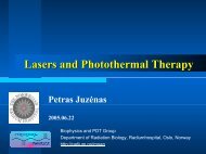
CeramOptec GmbH<br />
Medical applications : laser diodes at 732 nm Siemensstr. 44<br />
D-53121 Bonn<br />
Germany<br />
• 8W @ 732nm laser system<br />
– Applied <strong>for</strong> test of photo<br />
toxicity of photosensitizer<br />
• 10W @ 975nm laser system<br />
– Applied in dental<br />
applications<br />
• Cleaning of root canal<br />
• Cutting of soft tissue<br />
• 4W @ 732nm <strong>and</strong> 10W 975nm<br />
prototype laser system
CeramOptec GmbH<br />
Medical applications : laser diodes at 732 nm<br />
Coupling of 4W at 732nm from single emitters<br />
into an optical fibre with 400µm core <strong>and</strong> NA < 0.3<br />
• Bundle of 8 lasers (9 fibres)<br />
– ∅≈470µm, NA = 0.15<br />
– P ~ 11W<br />
• Coupling to application fibre<br />
– ∅ = 200µm, NA = 0.35<br />
– P ~ 8.4W<br />
• Outmatches originally planned<br />
specs significantly<br />
• Runs in “time- mode” = ON <strong>for</strong> pre- selected treatment time<br />
• Has been applied <strong>for</strong> test of photo- toxicity of photosensitizer
CeramOptec GmbH<br />
Application Test of 732 nm system I<br />
Evaluation of photo-toxicity of PDT substance (BLC2025)<br />
Typical test procedure<br />
• Growth of cell cultures<br />
• Incubation with photosensitizer in<br />
varying concentrations<br />
• Excitation of the sensitizer with<br />
different energy densities <strong>and</strong><br />
total energy<br />
• Continuation of cell growth<br />
• Determination of survival rate,<br />
e.g. via concentration of<br />
enzymes, which only exist in<br />
living cells<br />
100µl cell suspension per well
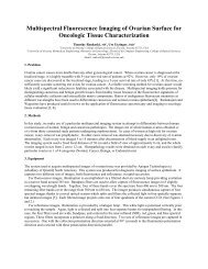
Application Test of 732 nm system II<br />
CeramOptec GmbH<br />
• HT29 cell line, 732 nm, BLC2025, 30 minutes incubation<br />
• Variation of photosensitizer concentration<br />
120<br />
100<br />
80<br />
60<br />
40<br />
20<br />
0<br />
0µM 10µM 20µM 30µM 40µM 50µM<br />
concentration BLC2025<br />
10J/cm2 0.5 W 12 sec 10J/cm2 1 W 6 sec 20J/cm2 0.5 W 25 sec<br />
20J/cm2 1 W 12 sec 50J/cm2 0.5 W 70 sec 50J/cm2 1 W 35 sec
CeramOptec GmbH<br />
Application Test of 732 nm system III<br />
• 30 µM BLC 2025, 50 J/cm2, 35 J<br />
• Variation of Treatment time with constant energy<br />
120<br />
100<br />
80<br />
60<br />
40<br />
20<br />
0<br />
0.5 W 70 sec 1 W 35 sec 2 W 17 sec 3 W 12 sec 4 W 9 sec 5 W 7 sec<br />
laser setting<br />
PBS HEK293 BLC2025 HEK293 BLC2025 HT29
CeramOptec GmbH<br />
Application Test of 975 nm system<br />
Cutting of soft tissue<br />
• Comparable conditions of wounds<br />
– 8h after treatment with 100µm<br />
core fibre<br />
– 24h after treatment with 400µm<br />
core fibre<br />
• <strong>High</strong>er power density leads to<br />
– more accurate cuts without<br />
carbonisation<br />
– Less postoperative pains<br />
– Slightly reduced treatment time
Application Test of 975 nm system<br />
Cleaning of root canal<br />
CeramOptec GmbH<br />
Advantages of smaller<br />
application fibre<br />
• Especially interesting<br />
in cases where a<br />
regular cleaning is not<br />
possible<br />
• Strong bended roots<br />
become accessible<br />
• Small space situations<br />
benefit from higher<br />
flexibility of fibre
At last :<br />
• Others laser diodes:<br />
-VCSELs (vertical emission), quantum cascade lasers (<br />
intra-b<strong>and</strong> recombination ), lasers with gratings (DFB,<br />
DBR) …<br />
- other wavelengthes<br />
- a lot of applications : Telecoms, dentistry, surgery, gas<br />
detection …<br />
• any questions