FT-60R - Yaesu UK Ltd
FT-60R - Yaesu UK Ltd
FT-60R - Yaesu UK Ltd

Create successful ePaper yourself
Turn your PDF publications into a flip-book with our unique Google optimized e-Paper software.
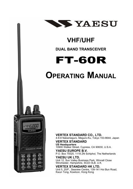
VHF/UHF<br />
DUAL BAND TRANSCEIVER<br />
<strong>FT</strong>-<strong>60R</strong><br />
OPERATING MANUAL<br />
VERTEX STANDARD CO., LTD.<br />
4-8-8 Nakameguro, Meguro-Ku, Tokyo 153-8644, Japan<br />
VERTEX STANDARD<br />
US Headquarters<br />
10900 Walker Street, Cypress, CA 90630, U.S.A.<br />
YAESU EUROPE B.V.<br />
P.O. Box 75525, 1118 ZN Schiphol, The Netherlands<br />
YAESU <strong>UK</strong> LTD.<br />
Unit 12, Sun Valley Business Park, Winnall Close<br />
Winchester, Hampshire, SO23 0LB, U.K.<br />
VERTEX STANDARD HK LTD.<br />
Unit 5, 20/F., Seaview Centre, 139-141 Hoi Bun Road,<br />
Kwun Tong, Kowloon, Hong Kong
General Description ......................................... 1<br />
Accessories & Options ..................................... 2<br />
Controls & Connections .................................. 3<br />
Top & Front Panel .......................................... 3<br />
LCD ................................................................ 4<br />
Side Panel ....................................................... 5<br />
Keypad ........................................................... 6<br />
Installation of Accessories ............................... 8<br />
Antenna Installation ....................................... 8<br />
Installation of FNB-83 Battery Pack ............. 8<br />
Battery Charging ............................................ 9<br />
Low Battery Indication ................................ 10<br />
Installation of FBA-25A Battery Case ......... 10<br />
Interface of Packet TNCs .............................. 11<br />
Operation ........................................................ 12<br />
Switching Power On and Off ....................... 12<br />
Adjusting the Audio Volume Level and<br />
Squelch Setting ....................................... 12<br />
Selecting the Operating Band ...................... 13<br />
Frequency Navigation .................................. 13<br />
Transmission ................................................ 15<br />
Advanced Operation ...................................... 16<br />
Keyboard Locking ........................................ 16<br />
Keypad/LCD Illumination ........................... 17<br />
Disabling the Keypad Beeper ...................... 17<br />
RF Squelch ................................................... 18<br />
Checking the Battery Voltage ...................... 18<br />
Repeater Operation ........................................ 19<br />
Repeater Shifts ............................................. 19<br />
Automatic Repeater Shift (ARS) ................. 19<br />
Manual Repeater Shift Activation ............... 20<br />
CTCSS/DCS Operation ................................. 22<br />
CTCSS Operation ........................................ 22<br />
DCS Operation ............................................. 23<br />
Tone Search Scanning ................................. 24<br />
CTCSS/DCS Bell Operation ........................ 25<br />
Split Tone Operation .................................... 25<br />
Tone Calling (1750 Hz) ............................... 26<br />
Memory Mode ................................................ 28<br />
Memory Storage ........................................... 28<br />
Storing Independent<br />
Transmit Frequencies (“Odd Split”) ........ 28<br />
Memory Recall ............................................. 29<br />
HOME Channel Memory ............................. 29<br />
Labeling Memories ...................................... 30<br />
Memory Offset Tuning ................................ 31<br />
Deleting Memories ....................................... 32<br />
Moving Memory Data to the VFO ............... 32<br />
Memory Bank Operation ............................. 33<br />
Memory Only Mode ..................................... 34<br />
Weather Broadcast Channels ....................... 34<br />
Contents<br />
Scanning .......................................................... 35<br />
VFO Scanning .............................................. 35<br />
Manual VFO Scan ................................... 35<br />
Programmed VFO Scan ........................... 36<br />
Memory Scanning ........................................ 37<br />
How to Skip (Omit) a Channel<br />
during Memory Scan Operation .............. 37<br />
Preferential Memory Scan ....................... 38<br />
Memory Bank Scan ................................. 39<br />
Weather Alert Scan ...................................... 39<br />
Programmable (Band Limit) Memory Scan<br />
(PMS) ........................................................... 40<br />
“Priority Channel” Scanning<br />
(Dual Watch) ................................................ 41<br />
Automatic Lamp Illumination<br />
on Scan Stop ................................................ 43<br />
Band Edge Beeper ........................................ 43<br />
EPCS (Enhanced Paging & Code Squelch) ............. 44<br />
Storing the CTCSS Tone Pairs<br />
for EPCS Operation ..................................... 44<br />
Activating the Enhanced Paging &<br />
Code Squelch System .................................. 45<br />
Paging Answer Back .................................... 45<br />
Emergency Feature ........................................ 46<br />
Emergency Channel Operation .................... 46<br />
Emergency Automatic ID (EAI) Feature ..... 46<br />
Smart Search Operation ................................ 48<br />
Internet Connection Feature ......................... 49<br />
ARTS (Automatic Range Transponder System) ....... 51<br />
DTMF Operation ........................................... 54<br />
Miscellaneous Settings ................................... 56<br />
Password ...................................................... 56<br />
Programming the Key Assignment .............. 57<br />
Changing the Channel Steps ........................ 57<br />
Changing the Receiving Mode .................... 58<br />
Receive Battery Saver Setup ........................ 59<br />
TX Battery Saver .......................................... 59<br />
Disabling the TX/BUSY Indicator .............. 60<br />
Automatic Power-Off (APO) Feature .......... 60<br />
Transmitter Time-Out Timer (TOT) ............ 61<br />
Busy Channel Lock-Out (BCLO) ................ 61<br />
Mono Band Operation ................................. 62<br />
Changing the TX Deviation Level ............... 62<br />
DCS Code Inversion .................................... 63<br />
Reset Procedures ............................................ 64<br />
Cloning ............................................................ 65<br />
Set Mode .......................................................... 66<br />
Specifications .................................................. 79<br />
“AUTO” Mode Preset Operating Parameters .... 80
GENERAL DESCRIPTION<br />
The <strong>FT</strong>-<strong>60R</strong> is a dual band FM transceiver with extensive receive frequency coverage,<br />
providing local-area two-way amateur communications along with unmatched monitoring<br />
capability.<br />
The <strong>FT</strong>-<strong>60R</strong>’s small size allows you to take it anywhere - hiking, skiing, or while walking<br />
around town - and its operating flexibility brings the user many avenues of operating enjoyment.<br />
Its incredibly tiny FNB-83 Rechargeable Nickel-Metal Hydride Battery Pack<br />
provides up to 5 Watts of transmit power on 144 MHz and 430 MHz Amateur Bands.<br />
Besides 144- and 430-MHz transceive operation, the <strong>FT</strong>-<strong>60R</strong> provides receive coverage<br />
of the VHF and UHF TV bands, the VHF AM aircraft band, and a wide range of commercial<br />
and public safety frequencies!<br />
New and exciting features of the <strong>FT</strong>-<strong>60R</strong> are the Emergency Automatic ID (EAI) function,<br />
that will automatically cause your <strong>FT</strong>-<strong>60R</strong> to transmit your callsign and engage your rig’s<br />
microphone, even if you are disabled and unable<br />
to press the PTT switch; Enhanced Paging and<br />
Code Squelch (EPCS), that allows you to page a<br />
particular station and only receive calls from that<br />
station, if desired; and a security Password feature,<br />
that will allow you to turn on and operate<br />
your transceiver only after you enter your Password.<br />
Additional features include a convenient access<br />
key for Vertex Standard’s WIRES (Wide-coverage<br />
Internet Repeater Enhancement System), a<br />
transmit Time-Out Timer (TOT), Automatic<br />
Power-Off (APO), Automatic Repeater Shift<br />
(ARS), <strong>Yaesu</strong>’s exclusive ARTS (Auto-Range<br />
Transponder System) which “beeps” the user when<br />
you move out of communications range with another<br />
ARTS equipped station, plus provision for<br />
reduction of the TX deviation in areas of high channel<br />
congestion. And an RF squelch circuit allows<br />
the owner to set the squelch to open at a programmable<br />
setting of the S-Meter, thus reducing guesswork<br />
in setting the squelch threshold.<br />
We appreciate your purchase of the <strong>FT</strong>-<strong>60R</strong>, and<br />
encourage you to read this manual thoroughly, so<br />
as to learn about the many exciting features of your<br />
exciting new <strong>Yaesu</strong> hand-held transceiver!<br />
<strong>FT</strong>-<strong>60R</strong> OPERATING MANUAL 1
ACCESSORIES & OPTIONS<br />
SUPPLIED ACCESSORIES<br />
FNB-83 7.2 V, 1,400 mAh<br />
Rechargeable Nickel-Metal Hydride Battery Pack<br />
NC-88B/C Overnight Battery Charger (10-Hour)<br />
Belt Clip<br />
Antenna<br />
Operating Manual<br />
Warranty Card<br />
AVAILABLE OPTIONS<br />
FNB-83 7.2 V, 1,400 mAh<br />
Rechargeable Nickel-Metal Hydride Battery Pack<br />
FBA-25A Compact Dry Battery Case for 6 AA-size cells<br />
CD-29B/C Rapid Charger (1.5-Hour)<br />
NC-88B/C Overnight Battery Charger (10-Hours)<br />
CN-3 BNC-to-SMA Adapter<br />
CT-27 Cloning Cable<br />
CT-44 Microphone Adapter<br />
E-DC-5B DC Cable with Cigarette-Lighter Adapter<br />
E-DC-6 DC Cable; plug and wire only<br />
MH-34B4B Speaker/Microphone<br />
MH-37A4B Ear piece/Microphone<br />
VC-25 VOX Headset<br />
: “B” suffix is for use with 100-120 VAC, “C” suffix is for use with 230-240 VAC.<br />
Availability of accessories may vary. Some accessories are supplied as standard per local<br />
requirements, while others may be unavailable in some regions. Consult your <strong>Yaesu</strong> dealer<br />
for details regarding these and any newly-available options. Connection of any non-<strong>Yaesu</strong>approved<br />
accessory, should it cause damage, may void the Limited Warranty on this apparatus.<br />
2<br />
<strong>FT</strong>-<strong>60R</strong> OPERATING MANUAL
CONTROL & CONNECTIONS (TOP & FRONT PANEL)<br />
Antenna Jack<br />
Connect the supplied rubber flex antenna (or another antenna presenting a 50-Ohm<br />
impedance) here.<br />
VOL/PWR Knob<br />
Turn this control clockwise to turn the radio on and to<br />
increase the volume. Counter-clockwise rotation into<br />
the click-stop will turn the radio off.<br />
TX/BUSY Indicator Lamp<br />
This indicator glows green when the squelch opens,<br />
and turns red during transmit.<br />
<br />
DIAL Knob<br />
This (inner) 20-position detented rotary switch is used for setting the operating frequency,<br />
and also is used for menu selections and other adjustments.<br />
SQL Knob<br />
This (outer) control is used to silence background<br />
noise on the receiver. It should be advanced<br />
clockwise just to the point where the<br />
noise is silenced (and the green “BUSY” indicator<br />
turns off).<br />
LCD (Liquid Crystal Display) <br />
The display shows current operating condition,<br />
as indicated on the next page.<br />
Speaker<br />
<br />
The internal speaker is located here.<br />
Microphone<br />
<br />
The internal microphone is located here.<br />
Keypad<br />
These 16 keys select many of most important <br />
operating features on the <strong>FT</strong>-<strong>60R</strong>. The functions<br />
of the keys are described in detail on the<br />
pages to follow.<br />
<strong>FT</strong>-<strong>60R</strong> OPERATING MANUAL 3
CONTROL & CONNECTIONS (LCD)<br />
Memory Channel Number<br />
Repeater Shift Direction<br />
Dual Watch Active<br />
Skip Memory Channel<br />
or Preferential Memory<br />
Channel<br />
Priority Channel<br />
Memory Bank Active<br />
Operating Mode<br />
Secondary Keypad<br />
Active<br />
Key Lock Active<br />
CTCSS/DSC Operation<br />
S- & PO Meter<br />
Low TX Power Selected<br />
Battery Saver Active<br />
Automatic Power-Off<br />
Active<br />
Internet Connection<br />
Feature Active<br />
Bell Alerm Active<br />
Operating Frequency<br />
Battery Indicator<br />
4<br />
<strong>FT</strong>-<strong>60R</strong> OPERATING MANUAL
CONTROL & CONNECTIONS (SIDE PANEL)<br />
PTT (Push To Talk) Switch<br />
Press this switch to transmit, and release it (to receive) after your transmission is completed.<br />
MONI Switch<br />
Pressing this switch disables the noise squelching action, allowing you to hear very<br />
weak signals near the background noise level temporarily.<br />
Press the [F/W] key on the keypad first, then press this switch to “open” the squelch<br />
continuously. Press this switch again to resume normal (quiet) monitoring.<br />
LAMP Switch<br />
Pressing this switch illuminates the LCD and keypad for five seconds, after which the<br />
back-lighting will automatically turn off.<br />
Press the [F/W] key on the keypad first, then press this switch to activate the backlighting<br />
lamp continuously. To turn the lamp off, press this switch again.<br />
You can change the primary (press key) function of this switch, if you prefer. See page<br />
17 for details.<br />
MIC/SP Jack<br />
This four-conductor<br />
miniature jack provides<br />
connection<br />
points for microphone<br />
audio, earphone audio,<br />
PTT, and ground.<br />
EXT DC Jack<br />
This coaxial DC jack<br />
allows connection to<br />
an external DC power<br />
source (6-16V DC).<br />
The center pin of this<br />
jack is the Positive (+)<br />
connection.<br />
<br />
<br />
<br />
<br />
<br />
MIC<br />
/SP<br />
EXT<br />
DC<br />
<strong>FT</strong>-<strong>60R</strong> OPERATING MANUAL 5
CONTROL & CONNECTIONS (KEYPAD)<br />
Primary Function<br />
(PRESS KEY)<br />
Frequency entry digit “1”<br />
Frequency entry digit “2”<br />
Secondary Function<br />
(PRESS [F/W] + KEY)<br />
Third Function<br />
(PRESS & HOLD KEY)<br />
Activates the CTCSS or DCS<br />
Operation<br />
Recalls the “Weather” broadcast<br />
channel bank<br />
Selects the CTCSS tone or DCS<br />
code number<br />
Activates the ARTS feature<br />
Primary Function<br />
(PRESS KEY)<br />
Secondary Function<br />
(PRESS [F/W] + KEY)<br />
Third Function<br />
(PRESS & HOLD KEY)<br />
Frequency entry digit “4”<br />
Selects the direction of the uplink<br />
frequency shift (either “–,” “+,” or<br />
“simplex”) during repeater operation<br />
Activates the EMERGENCY<br />
function<br />
1<br />
Frequency entry digit “5”<br />
Selects the CTCSS/DCS Bell ringer<br />
repetitions<br />
None<br />
1<br />
Primary Function<br />
(PRESS KEY)<br />
Frequency entry digit “7”<br />
Frequency entry digit “8”<br />
Secondary Function<br />
(PRESS [F/W] + KEY)<br />
Activates the EPCS (Enhanced<br />
Paging & Code Squelch) feature<br />
Selects the Memory Scan “Skip”<br />
channel-selection mode<br />
Third Function<br />
(PRESS & HOLD KEY)<br />
None<br />
None<br />
Primary Function<br />
(PRESS KEY)<br />
Secondary Function<br />
(PRESS [F/W] + KEY)<br />
Third Function<br />
(PRESS & HOLD KEY)<br />
Switches the frequency control<br />
between the VFO and Memory<br />
Systems<br />
Activates the Priority (Dual Watch)<br />
function<br />
Starts the programmable scanner<br />
upward (toward a higher frequency<br />
or a higher channel number)<br />
Activates the Internet Connection<br />
feature<br />
Frequency entry digit “0”<br />
Engages the Set (Menu) Mode<br />
Enables Internet access code<br />
selection<br />
1: You can program the secondary (press [F/W] key +) function of the key to another function, if<br />
desired. See page 57 for details.<br />
6<br />
<strong>FT</strong>-<strong>60R</strong> OPERATING MANUAL
CONTROL & CONNECTIONS (KEYPAD)<br />
Primary Function<br />
(PRESS KEY)<br />
Secondary Function<br />
(PRESS [F/W] + KEY)<br />
Third Function<br />
(PRESS & HOLD KEY)<br />
Frequency entry digit “3”<br />
Selects the desired transmit power<br />
output level<br />
Activates the Smart Search feature<br />
Increases the VFO frequency by<br />
one step or moves the memory<br />
channel to the next-highest channel<br />
Tunes the VFO frequency upward<br />
in 1 MHz steps<br />
Starts the scanner upward<br />
(toward a higher frequency or<br />
a higher channel number)<br />
Primary Function<br />
(PRESS KEY)<br />
Secondary Function<br />
(PRESS [F/W] + KEY)<br />
Third Function<br />
(PRESS & HOLD KEY)<br />
Primary Function<br />
(PRESS KEY)<br />
Secondary Function<br />
(PRESS [F/W] + KEY)<br />
Frequency entry digit “6”<br />
Activates the Key Lockout feature<br />
Activates the Key Lockout feature<br />
Frequency entry digit “9”<br />
Selects the DTMF mode<br />
Decreases the VFO frequency by<br />
one step or moves the memory<br />
channel to the next-lowest channel<br />
Tunes the VFO frequency downward<br />
in 1 MHz steps<br />
Starts the scanner downward<br />
(toward a lower frequency or a<br />
lower channel number)<br />
2<br />
Reverses the transmit and receive<br />
frequencies while working through<br />
a repeater<br />
Switches to the “Home” (favorite<br />
frequency) Channel<br />
Third Function<br />
(PRESS & HOLD KEY)<br />
None<br />
None<br />
Primary Function<br />
(PRESS KEY)<br />
Secondary Function<br />
(PRESS [F/W] + KEY)<br />
Third Function<br />
(PRESS & HOLD KEY)<br />
Moves operation to the nexthighest<br />
frequency band while in the<br />
VFO mode<br />
Activates the “Memory “Tune” mode<br />
while in the Memory Recall mode<br />
Moves operation to the next-lowest frequency band<br />
Selects the bandwidth for the<br />
programmable scanner while in the<br />
VFO mode<br />
Activates the “Secondary” key<br />
function<br />
Disables the “Secondary” key<br />
function<br />
Activates the “Memory Write” mode<br />
(for memory channel storage)<br />
2: You can exchange the function between primary (press key) function and secondary (press [F/W]<br />
key +) function, if desired. See page 74 for details.<br />
<strong>FT</strong>-<strong>60R</strong> OPERATING MANUAL 7
INSTALLATION OF ACCESSORIES<br />
ANTENNA INSTALLATION<br />
The supplied antenna provides good results over the entire frequency<br />
range of the transceiver. However, for enhanced reception<br />
on certain non-Amateur frequencies, you may wish to connect<br />
an antenna designed specifically for that frequency range,<br />
as the supplied antenna is necessarily a compromise outside the<br />
Amateur bands, and cannot be expected to provide high performance<br />
at all frequencies.<br />
To install the supplied antenna, hold the bottom end of the antenna,<br />
then screw it onto the mating connector on the transceiver<br />
until it is snug. Do not over-tighten by use of extreme force.<br />
Notes:<br />
Never transmit without having an antenna connected.<br />
When installing the supplied antenna, never hold the upper part of the antenna while<br />
screwing it onto the mating connector on the transceiver.<br />
If using an external antenna for transmission, ensure that the SWR presented to the<br />
transceiver is 1.5:1 or lower, to avoid excessive feedline loss.<br />
INSTALLATION OF FNB-83 BATTERY PACK<br />
The FNB-83 is a high-performance Ni-MH battery providing high capacity in a compact<br />
package. Under normal use, the FNB-83 may be used for approximately 300 charge cycles,<br />
after which operating time may be expected to decrease. If you have an old battery pack<br />
which is displaying capacity which has become diminished, you should replace the pack<br />
with a new one.<br />
Installation of the battery is easy and quick:<br />
Insert the battery pack into the battery compartment on the back of the<br />
radio while tilting the Belt Clip outward, then close the<br />
Battery Pack Latch until it locks in place<br />
with a “Click.”<br />
To remove the<br />
battery, turn the<br />
radio off and remove<br />
any protective<br />
cases.<br />
Open the Battery<br />
Pack Latch<br />
MIC<br />
/SP<br />
EXT<br />
DC<br />
Install the Battery Pack<br />
Close the Battery Pack Latch<br />
on the bottom of the radio, then slide the battery downward and out from the radio<br />
while tilting the Belt Clip out of the way.<br />
8<br />
<strong>FT</strong>-<strong>60R</strong> OPERATING MANUAL
INSTALLATION OF ACCESSORIES<br />
BATTERY CHARGING<br />
If the battery has never been used, or its charge is depleted, it may be charged by connecting<br />
the NC-88 Overnight Battery Charger, as shown in the illustration, to the EXT DC<br />
jack. If only 12 ~ 16 Volt DC power is available, the optional E-DC-5B DC Adapter (with<br />
its cigarette lighter plug) may also be used for charging the battery.<br />
A fully-discharged pack will be charged completely in 10 hours. Disconnect the NC-88<br />
from the EXT DC jack and the AC line outlet.<br />
Important Note<br />
The NC-88 is not designed to power the transceiver for operation (reception or<br />
transmission).<br />
Do not leave the NC-88 connected to the transceiver for continuous periods in excess<br />
of 24 hours. Long term overcharging can degrade the Ni-MH battery pack and<br />
significantly shorten its useful life.<br />
Please be advised that the NC-88 may contribute noise to TV and radio reception in<br />
the immediate vicinity, so we do not recommend its use adjacent to such devices.<br />
<br />
AC line outlet<br />
EXT DC jack<br />
<strong>FT</strong>-<strong>60R</strong> OPERATING MANUAL 9
INSTALLATION OF ACCESSORIES<br />
LOW BATTERY INDICATION<br />
As your battery discharges during use, the voltage will gradually become lower. When<br />
the battery voltage is becoming too low for reliable operation,<br />
the “ ” icon will blink on the LCD display, indicating that the<br />
battery pack must be recharged before further use.<br />
Avoid recharging Ni-MH batteries before the “ ” indicator is observed, as this can<br />
degrade the charge capacity of your Ni-MH battery pack.<br />
INSTALLATION OF FBA-25A ALKALINE BATTERY CASE ( OPTION )<br />
The optional FBA-25A Battery Case allows operation of the <strong>FT</strong>-<strong>60R</strong> using six “AA” size<br />
Alkaline batteries.<br />
When installing batteries, insert the (–) end first, then press in the (+) end so the battery<br />
snaps into place. Always replace all six batteries at the same time, paying attention to the<br />
polarity indicated inside the case.<br />
The FBA-25A must not be used with rechargeable cells. The FBA-25A does not contain<br />
the thermal and over-current protection circuits (provided in the “FNB” series of Ni-MH<br />
Battery Packs) required when utilizing Ni-Cd and Ni-MH cells.<br />
Note that the power output and battery life will be much shorter when using Alkaline AA<br />
cells. They should be considered an emergency backup power source only, for this reason.<br />
10<br />
<strong>FT</strong>-<strong>60R</strong> OPERATING MANUAL
INTERFACE OF PACKET TNCS<br />
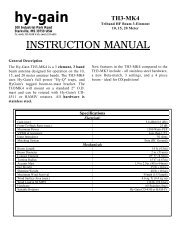
The <strong>FT</strong>-<strong>60R</strong> may be used for Packet operation, using the optional CT-44 microphone<br />
adapter (available from your <strong>Yaesu</strong> dealer) for easy interconnection to commonly-available<br />
connectors wired to your TNC. You may also build your own cable, using a fourconductor<br />
miniature phone plug, per the diagram below.<br />
The audio level from the receiver to the TNC may be adjusted by using the VOL knob, as<br />
with voice operation. The input level to the <strong>FT</strong>-<strong>60R</strong> from the TNC should be adjusted at<br />
the TNC side; the optimum input voltage is approximately 5 mV at 2000 Ohms.<br />
Be sure to turn the transceiver and TNC off before connecting the cables, so as to prevent<br />
voltage spikes from possibly damaging your transceiver.<br />
When you are operating on Packet, switch the Receive Battery Saver OFF, as the “sleep”<br />
cycle may “collide” with the beginning of an incoming Packet transmission, causing your<br />
TNC not to receive the full data burst. See page 59 for details regarding Battery Saver<br />
setup.<br />
MIC/SP<br />
EAR<br />
MIC<br />
+<br />
10µF<br />
2 kΩ<br />
SP<br />
GND<br />
MIC<br />
PTT<br />
GND<br />
TNC<br />
CT-44<br />
<strong>FT</strong>-<strong>60R</strong> OPERATING MANUAL 11
OPERATION<br />
Hi! I’m R. F. Radio, and I’ll be helping you along as you learn the many<br />
features of the <strong>FT</strong>-<strong>60R</strong>. I know you’re anxious to get on the air, but I encourage<br />
you to read the “Operation” section of this manual as thoroughly as<br />
possible, so you’ll get the most out of this fantastic new transceiver. Now. . .let’s get<br />
operating!<br />
<br />
<br />
<br />
SWITCHING POWER ON AND OFF<br />
Be sure the Battery Pack is installed, and that the battery<br />
is fully charged. Connect the antenna to the top panel<br />
Antenna jack.<br />
Rotate the top panel’s VOL knob out of the click-stop to<br />
turn on the radio. The current DC supply voltage will be<br />
indicated on the display for 2 seconds. After this 2 second<br />
interval, the display will resume its normal indication<br />
of the operating frequency.<br />
To turn the radio off, turn the VOL knob fully counter-clockwise into the click stop<br />
position.<br />
ADJUSTING THE AUDIO VOLUME LEVEL AND SQUELCH SETTING<br />
At first, set the SQL knob fully counter-clockwise. Now,<br />
you may rotate the VOL knob to adjust the receiver level<br />
for a comfortable listing level, using the background<br />
noise as a reference.<br />
To set the squelch, turn the SQL knob clockwise, slightly<br />
past the point where the background noise is muted. This<br />
is the point of best sensitivity to weak signals, and we<br />
recommend that you not rotate the SQL knob very much past the point where the<br />
background noise is just silenced.<br />
1) A special “RF Squelch” feature is provided on this radio. This feature<br />
allows you to set the squelch so that only signals exceeding a certain S-meter<br />
level will open the squelch. See page 18 for details.<br />
2) If you’re operating in an area of high RF pollution, you may need to consider “Tone<br />
Squelch” operation using the built-in CTCSS Decoder. This feature will keep your radio<br />
quiet until a call is received from a station sending a carrier which contains a matching<br />
(subaudible) CTCSS tone. Or, if your friends have radios equipped with DCS (Digital<br />
Coded Squelch) like your <strong>FT</strong>-<strong>60R</strong> has, try using that mode for silent monitoring of busy<br />
channels.<br />
12<br />
<strong>FT</strong>-<strong>60R</strong> OPERATING MANUAL
OPERATION<br />
<br />
<br />
<br />
SELECTING THE OPERATING BAND<br />
Press the [BAND(BAND DN)] key repetitively. You will<br />
see the LCD indication move toward a higher frequency<br />
band each time you press the [BAND(BAND DN)] key.<br />
850 MHz 144 MHz <br />
250 MHz 350 MHz <br />
430 MHz 850 MHz ……<br />
If you wish to move the operating band selection downward<br />
(toward a lower frequency band), press the [F/W]<br />
key first, then press the [BAND(BAND DN)] key.<br />
350 MHz 250 MHz <br />
144 MHz 850 MHz <br />
430 MHz 350 MHz ……<br />
Once you have selected the desired band, you<br />
may initiate manual tuning (or scanning) per<br />
the discussion in the next chapter.<br />
BAND<br />
144 MHz Band<br />
250 MHz Band<br />
350 MHz Band<br />
430 MHz Band<br />
850 MHz Band<br />
FREQUENCY RANGE<br />
108.000 - 200.000 MHz<br />
200.000 - 300.000 MHz<br />
300.000 - 400.000 MHz<br />
400.000 - 520.000 MHz<br />
700.000 - 999.990 MHz<br />
FREQUENCY NAVIGATION<br />
The <strong>FT</strong>-<strong>60R</strong> will initially be operating in the “VFO” mode, a channelized system which<br />
allows free tuning throughout the currently-selected operating band.<br />
Three basic frequency navigation methods are available on the <strong>FT</strong>-<strong>60R</strong>:<br />
1) Tuning Dial<br />
Rotation of the DIAL allows tuning in the pre-programmed<br />
steps established for the current operating band. Clockwise<br />
rotation of the DIAL causes the <strong>FT</strong>-<strong>60R</strong> to be tuned toward<br />
a higher frequency, while counter-clockwise rotation will<br />
lower the operating frequency.<br />
If you press the [F/W] key momentarily, then rotate the DIAL,<br />
frequency steps of 1 MHz will be selected. This feature is<br />
extremely useful for making rapid frequency excursions over the wide tuning range of the<br />
<strong>FT</strong>-<strong>60R</strong>.<br />
<strong>FT</strong>-<strong>60R</strong> OPERATING MANUAL 13
OPERATION<br />
FREQUENCY NAVIGATION<br />
2) Direct Keypad Frequency Entry<br />
The desired operating frequency may be entered directly from the keypad.<br />
To enter a frequency from the keypad, just press the numbered digits on the keypad in the<br />
proper sequence.<br />
Examples:<br />
To enter 146.560 MHz, press [1] [4] [6] [5] [6] [0]<br />
To enter 146.5625 MHz (in 12.5 kHz), [1] [4] [6] [5] [6] [2]<br />
3) Scanning<br />
Press and hold in either the [(MHz)] or [(MHz)] key<br />
for one second to initiate upward or downward scanning,<br />
respectively (Manual VFO Scan).<br />
For scanning within a limited sub-band range, from the VFO<br />
mode, press and hold in the [V/M(PRI)] key for one second<br />
to begin scanning toward a higher frequency within the previously-defined<br />
sub-band (Programmed VFO Scan). Details<br />
regarding sub-band setup may be found on page 36.<br />
If you wish to reverse the direction of the scan (i.e. toward a<br />
lower frequency, instead of a higher frequency), just rotate<br />
the DIAL one click in the counter-clockwise direction while<br />
the <strong>FT</strong>-<strong>60R</strong> is scanning. The scanning direction will be reversed.<br />
To revert to scanning toward a higher frequency once<br />
more, rotate the DIAL one click clockwise.<br />
(Manual VFO Scan)<br />
(Programmed VFO Scan)<br />
The scanner will stop when it receives a signal strong enough to break through the Squelch<br />
threshold. The <strong>FT</strong>-<strong>60R</strong> will then hold on that frequency according to the setting of the<br />
“RESUME” mode (Set Mode Item 34: RESUME). Press the PTT switch momentarily to<br />
cancel the scanning. This only stops the scan; it does not cause transmission to occur. See<br />
page 35 for details regarding Scan Operation.<br />
14<br />
<strong>FT</strong>-<strong>60R</strong> OPERATING MANUAL
TRANSMISSION<br />
Once you have set up an appropriate frequency inside one of the 144 MHz or 430 MHz<br />
Amateur bands on which the <strong>FT</strong>-<strong>60R</strong> can transmit, you’re ready to go on the air! These are<br />
the most basic steps; more advanced aspects of transmitter operation will be discussed later.<br />
<br />
<br />
<br />
To transmit, press the PTT switch, and speak into the<br />
front panel microphone (located in the lower left-hand<br />
corner of the speaker grille) in a normal voice level. The<br />
TX/BUSY indicator will glow red during transmission.<br />
To return to the receive mode, release the PTT switch.<br />
During transmission, the relative power level will be<br />
indicated on the bar graph at the bottom of the LCD;<br />
full scale deflection confirms “High Power” operation, while deflection of two bars<br />
indicates “Low Power” operation. Five bars indicates “Medium Power” operation.<br />
Additionally, the “LOW” icon will appear at the bottom of the display while operating<br />
on the “Low Power” and “Medium Power” settings.<br />
1) If you’re just talking to friends in the immediate area, you’ll get much longer<br />
battery life by switching to Low Power operation, described in the next chapter.<br />
And don’t forget: always have an antenna connected when you transmit.<br />
2) Transmission is possible only on the 144 MHz and 430 MHz bands.<br />
Changing the Transmitter Power Level<br />
To change the power level:<br />
Press the [F/W] key, then press the [3(TX PO)] key.<br />
The LCD shows the current power output level.<br />
Rotate the DIAL knob to select the desired power output<br />
level. Available selections are “HIGH” (5 W), “MID”<br />
(2 W), and “LOW” (0.5 W).<br />
When you have made your choice, press the PTT switch<br />
to save the new setting and return to normal operation.<br />
OPERATION<br />
1) The <strong>FT</strong>-<strong>60R</strong> is smart! You can set up Low power on the 144 MHz band,<br />
while leaving 430 MHz on High power, and the radio will remember the<br />
different settings on both bands. And when you store memories, you can store<br />
the power output settings separately in each memory, so you don’t waste battery power<br />
when using very close-in repeaters!<br />
2) When you are operating on the “Low” or “Medium” power setting, you can press the<br />
[F/W] key, when press the PTT switch, to cause the <strong>FT</strong>-<strong>60R</strong> to transmit (temporarily) on<br />
High power. After one transmission, the power level will revert to the previously-selected<br />
(“Low” or “Medium” power) setting.<br />
<strong>FT</strong>-<strong>60R</strong> OPERATING MANUAL 15
ADVANCED OPERATION<br />
Now that you’re mastered the basics of <strong>FT</strong>-<strong>60R</strong> operation, let’s learn more about some of<br />
the really neat features.<br />
KEYBOARD LOCKING<br />
In order to prevent accidental frequency change or inadvertent transmission, various aspects<br />
of the <strong>FT</strong>-<strong>60R</strong>’s DIAL and keypad may be locked out. The possible lockout combinations<br />
are:<br />
LK KEY: Just the front panel keypad is locked out<br />
LKDIAL: Just the top panel DIAL is locked out<br />
LK K+D: Both the keypad and DIAL are locked out (factory default)<br />
LK PTT: The PTT switch is locked out (TX not possible)<br />
LK P+K: Both the PTT switch and keypad are locked out<br />
LK P+D: Both the PTT switch and DIAL are locked out<br />
LK ALL: All of the above are locked out<br />
To lock out some or all of the keys:<br />
1. Press the [F/W] key, then press the [0( )SET] key to enter the Set mode.<br />
2. Rotate the DIAL knob to select Set Mode Item 25: LOCK.<br />
3. Press the [F/W] key momentarily to enable adjustment of this<br />
Item.<br />
4. Rotate the DIAL knob to choose between one of the locking<br />
schemes as outlined above.<br />
5. When you have made your selection, press the PTT switch to<br />
save the new setting and return to normal operation.<br />
To activate the locking feature, (1) press and hold in the<br />
[6(LOCK)] key for one second, or (2) press the [F/W] key,<br />
then press the [6(LOCK)] key. The “ ” icon will appear on<br />
the LCD. To cancel locking, repeat this process.<br />
16<br />
<strong>FT</strong>-<strong>60R</strong> OPERATING MANUAL
KEYPAD/LCD ILLUMINATION<br />
ADVANCED OPERATION<br />
Your <strong>FT</strong>-<strong>60R</strong> includes a reddish illumination lamp which aids in nighttime operation. The<br />
reddish illumination yields clear viewing of the display in a dark environment, with minimal<br />
degradation of your night vision.<br />
Three options for activating the lamp are provided:<br />
KEY Mode: Illuminates the Keypad/LCD lamp for five seconds when you rotate<br />
the DIAL knob or press the keypad or any switch (except PTT switch).<br />
This is the factory-programmed default setting.<br />
5SEC Mode: Illuminates the Keypad/LCD lamp for five seconds when you press<br />
the LAMP switch momentarily.<br />
TOGGLE Mode: Toggles the Keypad/LCD lamp on and off when you press the LAMP<br />
switch momentarily.<br />
Here is the procedure for setting up the Lamp operating mode:<br />
1. Press the [F/W] key, then press the [0( )SET] key to enter the Set mode.<br />
2. Rotate the DIAL knob to select Set Mode Item 24: LAMP.<br />
3. Press the [F/W] key momentarily to enable adjustment of this<br />
Item.<br />
4. Rotate the DIAL knob to select one of the three modes described<br />
above.<br />
5. When you have made your choice, press the PTT switch to save<br />
the new setting and return to normal operation.<br />
Press the [F/W] key first, then press the LAMP switch to illuminate the Keypad/LCD<br />
lamp continuously until you press the LAMP key again, irrespective<br />
of the Lamp mode programmed per the above instructions.<br />
DISABLING THE KEYPAD BEEPER<br />
A keypad beeper provides useful audible feed back whenever a keypad is pressed.<br />
If you want to turn the beep off:<br />
1. Press the [F/W] key, then press the [0( )SET] key to enter the Set mode.<br />
2. Rotate the DIAL knob to select Set Mode Item 6: BEEP.<br />
3. Press the [F/W] key momentarily to enable adjustment of this<br />
Item.<br />
4. Rotate the DIAL knob to change the setting to “OFF.”<br />
5. Press the PTT switch to save the new setting and return to normal<br />
operation.<br />
6. To turn the beep back on again, select “KEY” or “KEY+SC (factory default)” in step 4<br />
above.<br />
KEY: The beeper sounds when you press the keypad.<br />
KEY+SC: The beeper sounds when you press the keypad, or when the scanner stops.<br />
<strong>FT</strong>-<strong>60R</strong> OPERATING MANUAL 17
ADVANCED OPERATION<br />
RF SQUELCH<br />
A special RF Squelch feature is provided on this radio. This feature allows you to set the<br />
squelch so that only signals exceeding a certain S-meter level will open the squelch.<br />
To set up the RF squelch circuit for operation, use the following procedure:<br />
1. Press the [F/W] key, then press the [0( )SET] key to enter the Set mode.<br />
2. Rotate the DIAL knob to select Set Mode Item 37: RF SQL.<br />
3. Press the [F/W] key momentarily to enable adjustment of this<br />
Item.<br />
4. Rotate the DIAL knob to select the desired signal strength level<br />
for the squelch threshold (S-1, S-2, S-3, S-4, S-5, S-6, S-8, S-<br />
FULL, or OFF).<br />
5. Press the PTT switch to save the new setting and return to normal operation.<br />
6. Finally, rotate the SQL knob fully clockwise.<br />
CHECKING THE BATTERY VOLTAGE<br />
The <strong>FT</strong>-<strong>60R</strong>’s microprocessor includes programming which will measure the current battery<br />
voltage.<br />
1. Press the [F/W] key, then press the [0( )SET] key to enter the Set mode.<br />
2. Rotate the DIAL knob to select Set Mode Item 12: DC VLT.<br />
3. Press the [F/W] key momentarily to display the current DC voltage<br />
being supplied.<br />
4. Press the PTT switch to return to normal operation.<br />
18<br />
<strong>FT</strong>-<strong>60R</strong> OPERATING MANUAL
REPEATER OPERATION<br />
Repeater stations, usually located on mountaintops or other high locations, provide a dramatic<br />
extension of the communication range for low-powered hand-held or mobile transceivers.<br />
The <strong>FT</strong>-<strong>60R</strong> includes a number of features which make repeater operation simple<br />
and enjoyable.<br />
REPEATER SHI<strong>FT</strong>S<br />
Your <strong>FT</strong>-<strong>60R</strong> has been configured, at the factory, for the repeater shifts customary in your<br />
country. For the 144 MHz band shift will be 600 kHz; on the 430 MHz band, the shift may<br />
be 1.6 MHz, 7.6 MHz, or 5 MHz (USA version).<br />
Depending on the part of the band in which you are operating, the repeater shift may be<br />
either downward ( ) or upward ( ), and one<br />
of these icons will appear at the top of the LCD<br />
when repeater shifts have been enabled.<br />
AUTOMATIC REPEATER SHI<strong>FT</strong> (ARS)<br />
The <strong>FT</strong>-<strong>60R</strong> provides a convenient Automatic Repeater Shift feature, which causes the<br />
appropriate repeater shift to be applied automatically whenever you tune into the designated<br />
repeater sub-bands in your country. These sub-bands are shown below.<br />
If the ARS feature does not appear to be working, you may have accidentally disabled it.<br />
To re-enable ARS:<br />
1. Press the [F/W] key, then press the [0( )SET] key to enter the Set mode.<br />
2. Rotate the DIAL knob to select Set Mode Item 4: ARS.<br />
3. Press the [F/W] key momentarily to enable adjustment of this<br />
Item.<br />
4. Rotate the DIAL knob to select “ARS. ON.”<br />
5. When you have made your selection, press the PTT switch to<br />
save the new setting and return to normal operation.<br />
<strong>FT</strong>-<strong>60R</strong> OPERATING MANUAL 19
REPEATER OPERATION<br />
MANUAL REPEATER SHI<strong>FT</strong> ACTIVATION<br />
If the ARS feature has been disabled, or if you need to set a repeater shift direction other<br />
than that established by the ARS, you may set the direction of the repeater shift manually.<br />
To do this:<br />
1. Press the [F/W] key, then press the [0( )SET] key to enter the Set mode.<br />
2. Rotate the DIAL knob to select Set Mode Item 38: RPT.MOD.<br />
3. Press the [F/W] key momentarily to enable adjustment of this<br />
Item.<br />
4. Rotate the DIAL knob to select the desired shift among “RPT.–,”<br />
“RPT.+,” and “RPT.OFF.”<br />
5. When you have made your selection, press the PTT switch to<br />
save the new setting and return to normal operation.<br />
If you make a change in the shift direction, but still have Automatic Repeater<br />
Shift still engaged (see previous section), when you change frequency (by<br />
rotating the DIAL knob, for example) the ARS will over-ride your manual<br />
setting of the shift direction. Turn ARS off if you do not wish this to happen.<br />
Changing the Default Repeater Shifts<br />
If you travel to a different region, you may need to change the default repeater shift so as to<br />
ensure compatibility with local operating requirements.<br />
To do this, follow the procedure below:<br />
1. Set the <strong>FT</strong>-<strong>60R</strong>’s frequency to the band on which you wish to change the default<br />
repeater shift (144 MHz or 430 MHz Amateur Band).<br />
2. Press the [F/W] key, then press the [0( )SET] key to enter the Set mode.<br />
3. Rotate the DIAL knob to select Set Mode Item 45: SHI<strong>FT</strong>.<br />
4. Press the [F/W] key momentarily to enable adjustment of this<br />
Item.<br />
5. Rotate the DIAL knob to select the new repeater shift magnitude.<br />
6. When you have made your selection, press the PTT switch to<br />
save the new setting and return to normal operation.<br />
If you just have one “odd” split that you need to program, don’t change the<br />
“default” repeated shifts using this Set Mode Item. Enter the transmit and<br />
receive frequencies separately, as shown on page 28.<br />
20<br />
<strong>FT</strong>-<strong>60R</strong> OPERATING MANUAL
Checking the Repeater Uplink (Input) Frequency<br />
It often is helpful to be able to check the uplink (input) frequency of a repeater, to see if the<br />
calling station is within direct (“Simplex”) range.<br />
To do this, just press the [HM/RV] key. You’ll notice that<br />
the display has shifted to the repeater uplink frequency. Press<br />
the [HM/RV] key again to cause operation to revert to normal<br />
monitoring of the repeater downlink (output) frequency.<br />
While you are listening on the input frequency to the repeater<br />
using the [HM/RV] key, the repeater offset icon will<br />
blink.<br />
REPEATER OPERATION<br />
MANUAL REPEATER SHI<strong>FT</strong> ACTIVATION<br />
The configuration of this key may be set either to “RV” (for checking the<br />
input frequency of a repeater), or “HM” (for instant switching to the “Home”<br />
channel for the band you are operating on). To change the configuration of<br />
this key, use Set Mode Item 36: REV/HM. See page 75.<br />
<strong>FT</strong>-<strong>60R</strong> OPERATING MANUAL 21
CTCSS/DCS OPERATION<br />
22<br />
CTCSS OPERATION<br />
Many repeater systems require that a very-low-frequency audio tone be superimposed on<br />
your FM carrier in order to activate the repeater. This helps prevent false activation of the<br />
repeater by radar or spurious signals from other transmitters. This tone system, called<br />
“CTCSS” (Continuous Tone Coded Squelch System), is included in your <strong>FT</strong>-<strong>60R</strong>, and is<br />
very easy to activate.<br />
CTCSS setup involves two actions: setting the Tone Mode and then setting of<br />
the Tone Frequency. These actions are set up by using the [1(SQ TYP)] key<br />
and [2(CODE)] key.<br />
1. Press the [F/W] key, then press the [1(SQ TYP)] key to enable selection of the CTCSS/<br />
DCS mode.<br />
2. Rotate the DIAL knob so that “TONE” indication appears on the<br />
display; this activates the CTCSS Encoder, for access to repeaters<br />
requiring a CTCSS tone.<br />
3. Rotation of the DIAL knob one more “click” in step “2” above will cause the “TSQL”<br />
notation to appear. When “TSQL” is displayed, this means that the Tone SQueLch<br />
system is active, which mutes your <strong>FT</strong>-<strong>60R</strong>’s receiver until it receives a call from<br />
another radio sending out a matching CTCSS tone. This can<br />
help keep your radio quiet until a specific call is received, which<br />
may be helpful while operating in congested areas of the band.<br />
1) You may notice a “REV TN” indication on the display while you rotate<br />
the DIAL knob in this step; this means that the Reverse Tone Squelch<br />
system is active, which mutes your <strong>FT</strong>-<strong>60R</strong>’s receiver (instead of opening<br />
the squelch) when it receives a call from the radio sending a matched CTCSS tone.<br />
The “TSQ” icon will blink on the display when the Reverse Tone Squelch system is<br />
activated.<br />
2) You may notice a “DCS” indication on the display while you rotate the DIAL<br />
knob still more. We’ll discuss the Digital Code Squelch system shortly.<br />
4. When you have made your selection of the CTCSS tone mode, press the PTT switch<br />
to save the new setting.<br />
5. Press the [F/W] key, then press the<br />
[2(CODE)] key to enable adjustment of<br />
the CTCSS frequency.<br />
6. Rotate the DIAL knob until the display<br />
indicates the Tone Frequency you need to<br />
be using (ask the<br />
repeater owner/<br />
operator if you<br />
don’t know the tone frequency).<br />
CTCSS TONE FREQUENCY (Hz)<br />
67.0 69.3 71.9 74.4 77.0 79.7<br />
82.5 85.4 88.5 91.5 94.8 97.4<br />
100.0 103.5 107.2 110.9 114.8 118.8<br />
123.0 127.3 131.8 136.5 141.3 146.2<br />
151.4 156.7 159.8 162.2 165.5 167.9<br />
171.3 173.8 177.3 179.9 183.5 186.2<br />
189.9 192.8 196.6 199.5 203.5 206.5<br />
210.7 218.1 225.7 229.1 233.6 241.8<br />
250.3 254.1 – – – –<br />
<strong>FT</strong>-<strong>60R</strong> OPERATING MANUAL
CTCSS/DCS OPERATION<br />
CTCSS OPERATION<br />
7. When you have made your selection, press the [F/W] key momentarily to save the new<br />
settings and exit to normal operation. This is different than the<br />
usual method of restoring normal operation, and it applies only<br />
to the configuration of the CTCSS/DCS frequencies.<br />
Your repeater may or may not re-transmit a CTCSS tone - some systems just<br />
use CTCSS to control access to the repeater, but don’t pass it along when<br />
transmitting. If the S-Meter deflects, but the <strong>FT</strong>-<strong>60R</strong> is not passing audio,<br />
repeat steps “1” through “4” above, but rotate the DIAL so that “TSQ” disappears - this<br />
will allow you to hear all traffic on the channel being utilized.<br />
DCS OPERATION<br />
Another form of tone access control is Digital Code Squelch, or DCS. It is a newer, more<br />
advanced tone system which generally provides more immunity from false paging than<br />
does CTCSS. The DCS Encoder/Decoder is built into your <strong>FT</strong>-<strong>60R</strong>, and operation is very<br />
similar to that just described for CTCSS. Your repeater system may be configured for<br />
DCS; if not, DCS is frequently quite useful in Simplex operation if your friend(s) use<br />
transceivers equipped with this advanced feature.<br />
Just as in CTCSS operation, DCS requires that you set the Tone Mode to DCS and that<br />
you select a tone code.<br />
1. Press the [F/W] key, then press the [1(SQ TYP)] key to enable selection of the CTCSS/<br />
DCS mode.<br />
2. Rotate the DIAL knob until the “DCS” indication appears on the<br />
display; this activates the DCS Encoder/Decoder.<br />
3. Press the PTT key to save the new setting.<br />
4. Press the [F/W] key, then press the [2(CODE)] key to enable<br />
adjustment of the DCS code.<br />
5. Rotate the DIAL knob to select the desired DCS Code (a threedigit<br />
number). Ask the repeater owner/operator<br />
if you don’t know DCS Code; if<br />
you are working simplex, just set up the<br />
DCS Code to be the same as that used by<br />
your friend(s).<br />
6. When you have made your selection, press<br />
the [F/W] key momentarily to save the<br />
new settings and<br />
exit to normal operation.<br />
DCS CODE<br />
023 025 026 031 032 036 043 047 051 053<br />
054 065 071 072 073 074 114 115 116 122<br />
125 131 132 134 143 145 152 155 156 162<br />
165 172 174 205 212 223 225 226 243 244<br />
245 246 251 252 255 261 263 265 266 271<br />
274 306 311 315 325 331 332 343 346 351<br />
356 364 365 371 411 412 413 423 431 432<br />
445 446 452 454 455 462 464 465 466 503<br />
506 516 523 526 532 546 565 606 612 624<br />
627 631 632 654 662 664 703 712 723 731<br />
732 734 743 754 – – – – – –<br />
<strong>FT</strong>-<strong>60R</strong> OPERATING MANUAL 23
CTCSS/DCS OPERATION<br />
Remember that the DCS is an Encode/Decode system, so your receiver will<br />
remain muted until a matching DCS code is received on an incoming transmission.<br />
Switch the DCS off when you’re just tuning around the band!<br />
TONE SEARCH SCANNING<br />
In operating situations where you don’t know the CTCSS or DCS tone being used by<br />
another station or stations, you can command the radio to listen to the incoming signal and<br />
scan in search of the tone being used. Two things must be remembered in this regard:<br />
<br />
<br />
DCS OPERATION<br />
You must be sure that your repeater uses the same tone type (CTCSS vs. DCS).<br />
Some repeaters do not pass the CTCSS tone; you may have to listen to the station(s)<br />
transmitting on the repeater uplink (input) frequency in order to allow Tone Search<br />
Scanning to work.<br />
To scan for the tone in use:<br />
1. Set the radio up for either CTCSS or DCS Decoder operation (see the previous discussions).<br />
In the case of CTCSS, “ ” will appear on the display; in the case of DCS,<br />
“ ” will appear on the display.<br />
2. Press the [F/W] key, then press the [2(CODE)] key.<br />
3. Press and hold in the [(MHz)] or [(MHz)] key for one second<br />
to start scanning for the incoming CTCSS or DCS tone/<br />
code.<br />
4. When the radio detects the correct tone or code, it will halt on<br />
that tone/code, and audio will be allowed to pass. Press the<br />
[F/W] key to lock in that tone/code, then press the [F/W] key again to exit to normal<br />
operation.<br />
If the Tone Scan feature does not detect a tone or code, it will continue to<br />
scan indefinitely. When this happens, it may be that the other station is not<br />
sending any tone. You can press the PTT switch to halt the scan at any time.<br />
You also can press the MONI key during Tone Scanning to listen to the (muted) signal<br />
from the other station. When you release the MONI key, Tone Scanning will resume after<br />
about a second.<br />
Tone Scanning works either in the VFO or Memory modes.<br />
24<br />
<strong>FT</strong>-<strong>60R</strong> OPERATING MANUAL
CTCSS/DCS OPERATION<br />
CTCSS/DCS BELL OPERATION<br />
During CTCSS Decode or DCS operation, you may set up the <strong>FT</strong>-<strong>60R</strong> such that a ringing<br />
“bell” sound alerts you to the fact that a call is coming in. Here is the procedure for activating<br />
the CTCSS/DCS Bell:<br />
1. Set the transceiver up for CTCSS Decode (“Tone Squelch”) or DCS operation, as<br />
described previously.<br />
2. Adjust the operating frequency to the desired channel.<br />
3. Press the [F/W] key, then press the [5(BELL)] key.<br />
4. Rotate the DIAL knob to set the desired number of rings of the<br />
Bell. The available choices are “1 T,” “3 T,” “5 T,” or “8 T”<br />
rings, “CONT” (continuous ringing), or “OFF.”<br />
5. Press the PTT switch momentarily to save the new setting and exit to normal operation.<br />
When you are called by a station whose transceiver is sending a<br />
CTCSS tone or DCS code which matches that set into your Decoder,<br />
the Bell will ring in accordance with this programming.<br />
SPLIT TONE OPERATION<br />
The <strong>FT</strong>-<strong>60R</strong> can be operated in a Split Tone configuration via the Set mode.<br />
1. Press the [F/W] key, then press the [0( )SET] key to enter the Set mode.<br />
2. Rotate the DIAL knob to select Set Mode Item 47: SPLIT.<br />
3. Press the [F/W] key momentarily to enable adjustment of this<br />
Set Mode Item.<br />
4. Rotate the DIAL knob to select ON (to enable the Split Tone<br />
feature).<br />
5. Press the PTT key momentarily to save the new setting and exit<br />
to normal operation.<br />
When the Split Tone feature is activated, you can see the following additional parameters<br />
following the “DCS” parameter (while selecting the tone mode by pressing [F/W] <br />
[1(SQ TYP)]):<br />
D: DCS Encode only (the “ ” icon will blink during operation)<br />
T DCS: Encodes a CTCSS Tone and Decodes a DCS code<br />
(the “ ” icon will blink and the “ ” icon will appear during operation)<br />
D TSQL: Encodes a DCS code and Decodes a CTCSS Tone<br />
(the “ ” icon will appear and the “ ” icon will blink during operation)<br />
Select the desired operating mode, from the selections shown above.<br />
<strong>FT</strong>-<strong>60R</strong> OPERATING MANUAL 25
CTCSS/DCS OPERATION<br />
TONE CALLING (1750 HZ)<br />
If the repeaters in your country require a 1750-Hz burst tone for access (typically in Europe),<br />
you can set the MONI key to serve as a “Tone Call” switch instead. To change the<br />
configuration of this switch, we again use the Set Mode to help us.<br />
1. Press the [F/W] key, then press the [0( )SET] key to enter the Set mode.<br />
2. Rotate the DIAL knob to select Set Mode Item 26: M/T-CL.<br />
3. Press the [F/W] key momentarily to enable adjustment of this<br />
Set Mode Item.<br />
4. Rotate the DIAL knob to select “TCALL” on the display.<br />
5. Press the PTT switch to save the new setting and exit to normal<br />
operation.<br />
To access a repeater, press and hold in the MONI key for the amount of time specified by<br />
the repeater owner/operator. The transmitter will automatically be activated, and a 1750-<br />
Hz audio tone will be superimposed on the carrier. Once access to the repeater has been<br />
gained, you may release the MONI key, and use the PTT key for activating the transmitter<br />
thereafter.<br />
26<br />
<strong>FT</strong>-<strong>60R</strong> OPERATING MANUAL
MEMORY MODE<br />
The <strong>FT</strong>-<strong>60R</strong> provides a wide variety of memory system resources. These include:<br />
1000 “Standard” memory channels, numbered “000” through “999.”<br />
5 “Home” channels, providing storage and quick recall of one prime frequency on<br />
each operating band.<br />
50 sets of band-edge memories, also known as “Programmable Memory Scan” channels,<br />
labeled “L01/U01” through “L50/U50.”<br />
10 Memory Banks, labeled “BANK 1” through “BANK10.” Each Memory Bank can<br />
be assigned up to 1000 channels from the “standard” and “PMS” memory channels.<br />
10 “Weather Broadcast” Channels.<br />
Standard Memory Channels<br />
(1000 channels)<br />
PMS Memory Channels<br />
(50 Sets)<br />
1<br />
2<br />
3<br />
4<br />
999<br />
998<br />
000<br />
L2/U2<br />
L1/U1<br />
L4/U4<br />
L3/U3<br />
L49/U49<br />
L48/U48<br />
L50/U50<br />
Memory Bank 3<br />
Memory Bank 2<br />
Memory Bank 1<br />
Memory Bank 5<br />
Memory Bank 4<br />
Memory Bank 7<br />
Memory Bank 6<br />
Memory Bank 8<br />
Memory Bank 9<br />
Memory Bank 10<br />
Memory Banks<br />
(10 banks)<br />
Weather Broadcast Channels<br />
(10 channels)<br />
HOME Channels<br />
(5 channels)<br />
WX1<br />
WX3<br />
WX2<br />
WX4<br />
WX9<br />
WX10<br />
144 MHz Band<br />
350 MHz Band<br />
250 MHz Band<br />
850 MHz Band<br />
430 MHz Band<br />
<strong>FT</strong>-<strong>60R</strong> OPERATING MANUAL 27
MEMORY MODE<br />
MEMORY STORAGE<br />
1. Select the desired frequency, while operating in the VFO mode. Be sure to set up any<br />
desired CTCSS or DCS tones, as well as any desired repeater offset. The power level<br />
may also be set at this time, if you wish to store it.<br />
2. Press and hold in the [F/W] key for one second.<br />
3. Within five seconds of releasing the [F/W] key, you need to make a decision regarding<br />
channel storage. The microprocessor will automatically select the next-available “free”<br />
channel (a memory register on which no data has been stored), so you may not wish to<br />
make any change; if this is the case, proceed to step 4. If you wish to select a different<br />
channel number into which to store the data, rotate the DIAL knob to select the desired<br />
memory channel. You may jump 100 memory channels, if you’re in a hurry (101 <br />
201 301 …) by pressing the [BAND(BAND DN)] key (multiple times, if necessary).<br />
4. Press the [F/W] key once more to store the frequency into memory.<br />
5. You still will be operating in the “VFO” mode, so you may now enter other frequencies,<br />
and store them into additional memory locations, by repeating the above process.<br />
Storing Independent Transmit Frequencies (“Odd Splits”)<br />
All memories can store an independent transmit frequency, for operation on repeaters with<br />
non-standard shift. To do this:<br />
1. Store the receive frequency using the method already described under MEMORY<br />
STORAGE (it doesn’t matter if a repeater offset is active).<br />
2. Turn to the desired transmit frequency, then press and hold in the [F/W] key for one<br />
second.<br />
3. Within five seconds of releasing the [F/W] key, rotate the DIAL knob to select the<br />
same memory channel number as used in step “1” above.<br />
4. Press and hold in the PTT switch, then press the [F/W] key once more momentarily<br />
while holding the PTT switch in (this does not key the transmitter).<br />
Whenever you recall a memory which contains independently-stored<br />
transmit and receive frequencies, the<br />
“ ” indication will appear in the display.<br />
28<br />
<strong>FT</strong>-<strong>60R</strong> OPERATING MANUAL
MEMORY RECALL<br />
MEMORY MODE<br />
1. While operating in the VFO mode, press the [V/M(PRI)] key to enter the Memory<br />
mode.<br />
2. Rotate the DIAL knob to select the desired channel.<br />
3. To return to the VFO mode, press the [V/M(PRI)] key.<br />
When the radio is already set to the Memory mode, an easy way to recall memories is to<br />
key in the memory channel number, then press the [F/W] key.<br />
For example, to recall memory channel #14, press [1] [4] [F/W].<br />
You may also recall the Memory Channel #000 and Programmable Memory channels (“L01/<br />
U01” through “L50/U50.”) using the following numbers: Memory Channel #000 = “1000,”<br />
Programmable Memory channels #L1 = “1001,” U1 = “1002,” L50 = “1099,” and U50 =<br />
“1100.”<br />
HOME CHANNEL MEMORY<br />
A special one-touch “HOME” channel is available for each of operating bands, to allow<br />
quick recall of a favorite operating frequency on each band.<br />
Home Channel storage is simple to accomplish:<br />
1. Change the setting of Set Mode Item 35: REV/HM from “REV” to “HOME,” if it is not<br />
already set to this option (see page 75).<br />
2. Select the desired frequency, while operating in the VFO mode. Be sure to set up any<br />
desired CTCSS or DCS tones, as well as any desired repeater offset. The power level<br />
may also be set at this time, if you wish to store it.<br />
3. Press and hold in the [F/W] key for one second.<br />
4. While the memory channel number is blinking, just press the [HM/RV] key. The frequency<br />
and other data (if any) will now be stored in the special HOME channel register.<br />
5. You may repeat this process on the other operating bands.<br />
6. To recall the HOME channel,<br />
press the [HM/RV] key momentarily<br />
while operating either in the<br />
VFO or MR mode.<br />
DEFAULT HOME CHANNELS<br />
BAND<br />
144 MHz Band<br />
250 MHz Band<br />
350 MHz Band<br />
430 MHz Band<br />
850 MHz Band<br />
FREQUENCY<br />
146.520 MHz<br />
250.000 MHz<br />
350.000 MHz<br />
446.000 MHz<br />
850.000 MHz<br />
The UHF HOME channel is the one used during “Emergency channel operation.”<br />
See page 46 for details regarding this feature.<br />
<strong>FT</strong>-<strong>60R</strong> OPERATING MANUAL 29
MEMORY MODE<br />
LABELING MEMORIES<br />
You may wish to append an alpha-numeric “Tag” (label) to a memory or memories, to aid<br />
in recollection of the channel’s use (such as a club name, etc.). This is easily accomplished<br />
using the Set Mode.<br />
1. Recall the memory channel on which you wish to append a label.<br />
2. Press the [F/W] key, then press the [0( )SET] key to enter the<br />
Set mode.<br />
3. Rotate the DIAL knob to select Set Mode Item 28: NM WRT.<br />
4. Press the [F/W] key momentarily to display the previously stored<br />
label (if any).<br />
5. Press the [F/W] key again to clear any previous label.<br />
6. Rotate the DIAL knob to select the first digit of the desired label.<br />
7. Press the [F/W] key to move to the next character.<br />
8. If you make a mistake, press the [(MHz)] key to back-space the cursor, then re-enter<br />
the correct letter, number, or symbol.<br />
9. Repeat steps 5 through 7 to program the remaining letters, numbers, or symbols of the<br />
desired label. A total of six characters may be used in the creation of a label.<br />
10. When you have programmed a label which is under 6 characters, press and hold in the<br />
[F/W] key for one second to confirm the label (if the label is<br />
exactly 6 characters in length, you do not need to press and hold<br />
in [F/W]).<br />
11. When you have completed the creation of the label, press the PTT key to save the<br />
label and exit.<br />
To display the alpha-numeric “Tag” (label):<br />
1. Set the <strong>FT</strong>-<strong>60R</strong> to the “MR” (Memory Recall) mode, and recall<br />
the memory channel on which you wish to display its label.<br />
2. Press the [F/W] key, then press the [0( )SET] key to enter the<br />
Set mode.<br />
3. Rotate the DIAL knob to select the Set Mode Item labeled 27:<br />
NAME.<br />
4. Press the [F/W] key momentarily to enable adjustment of this<br />
Item’s setting.<br />
5. Rotate the DIAL knob to set this Set Mode Item to “ALPHA”<br />
(thus enabling the alpha-numeric display).<br />
6. Press the PTT key to save the new setting and activate the alpha-numeric<br />
Tag.<br />
30<br />
<strong>FT</strong>-<strong>60R</strong> OPERATING MANUAL
LABELING MEMORIES<br />
MEMORY MODE<br />
To disable the alpha-numeric Tag (enabling the frequency display), just repeat the above<br />
procedure, rotating the DIAL knob to select “FREQ” in step 5 above.<br />
You may set up some memory channels to have their frequencies displayed,<br />
while others may be set to have their Name Tag displayed; the selection within<br />
Set Mode Item 27 is not applied to all memory channels at once (just the<br />
channel on which you currently are operating).<br />
MEMORY OFFSET TUNING<br />
Once you have recalled a particular memory channel, you may easily tune off that channel,<br />
as though you were in the “VFO” mode.<br />
1. With the <strong>FT</strong>-<strong>60R</strong> in the “MR” (Memory Recall) mode, select<br />
the desired memory channel.<br />
2. Press the [BAND(BAND DN)] key momentarily to activate the<br />
“Memory Tuning” feature. The Memory Channel number will<br />
be replaced by “tun.” And if you have an alpha-numeric Tag<br />
displayed on the memory channel, the display will automatically<br />
revert to display of the operating frequency, so you can<br />
navigate without having to enter the Menu to change the display<br />
configuration.<br />
3. Rotate the DIAL knob, as desired, to tune to a new frequency.<br />
The synthesizer steps selected for VFO operation on the current<br />
band will be the steps used during Memory Tuning.<br />
4. If you wish to return to the original memory frequency, just press the [BAND(BAND<br />
DN)] key momentarily. The display will revert to display of the alpha-numeric Tag (if<br />
any) that may have originally appeared on the LCD.<br />
5. If you wish to store a new frequency set during Memory Tuning, just press and hold in<br />
the [F/W] key for one second, per normal memory storage procedure. The microprocessor<br />
will automatically set itself to the next-available clear memory location, and<br />
you then press [F/W] again to lock in the new frequency.<br />
1) If you want to replace the original memory contents with those of the new<br />
frequency, be sure to rotate the DIAL knob to the original memory channel<br />
number!<br />
2) Any required CTCSS/DCS changes, or repeater offset modifications, must be done<br />
before storing the data into the new (or original) memory channel location.<br />
<strong>FT</strong>-<strong>60R</strong> OPERATING MANUAL 31
MEMORY MODE<br />
DELETING MEMORIES<br />
You may desire to delete the memories (except the Memory Channel “1” and Home Channel).<br />
The procedure for deleting a channel is quite simple.<br />
1. Press the [V/M(PRI)] key, if needed, to enter the MR mode.<br />
2. Press and hold in the [F/W] key for one second, then rotate the DIAL knob to select<br />
the memory channel to be “deleted.”<br />
3. Press the [HM/RV] key momentarily. The display will revert to memory channel #1.<br />
The previously-selected memory will be deleted.<br />
Important Notice! Once deleted, the channel data cannot be recovered!<br />
MOVING MEMORY DATA TO THE VFO<br />
Data stored on memory channels can easily be moved to the VFO, if you like.<br />
1. Select the memory channel containing the frequency data to be moved to the VFO.<br />
2. Press the [BAND(BAND DN)] key momentarily to activate the “Memory Tune” feature<br />
temporarily, then press and hold in the [BAND(BAND DN)] key for one second.<br />
The data will now have been copied to the VFO, although the original memory contents<br />
will remain intact on the previously-stored channel.<br />
If a Split Frequency Memory channel was transferred, the TX frequency will<br />
be ignored (you will be set up for Simplex operation on the Receive frequency).<br />
32<br />
<strong>FT</strong>-<strong>60R</strong> OPERATING MANUAL
MEMORY BANK OPERATION<br />
MEMORY MODE<br />
The large number of memories available in the <strong>FT</strong>-<strong>60R</strong> could be difficult to utilize without<br />
some means of organizing them. Fortunately, the <strong>FT</strong>-<strong>60R</strong> includes provision for dividing<br />
the memories into as many as ten Memory Groups, so you can categorize the memories in<br />
a manner convenient to you. You may enter and exit the “Memory Group” mode by a<br />
single press of the [BAND(BAND DN)] key, as we shall see below.<br />
Assigning Memories to a Memory Bank<br />
1. Recall the memory channel to be assigned to a Memory Bank.<br />
2. Press and hold in the [BAND(BAND DN)] key for one second,<br />
then rotate the DIAL knob to select the Memory Bank number<br />
you want as the Memory Bank for this channel (“BANK 1” ~<br />
“BANK10”).<br />
3. Press and hold in the [F/W] key for one second to copy the memory<br />
channel data into the Memory Bank.<br />
1) You may assign one<br />
memory channel into several<br />
Memory Banks.<br />
2) The PMS memory channels (L1/U1<br />
through L50/U50) may not be assigned<br />
to a Memory Bank.<br />
Memory Channel<br />
CH 000 145.000 MHz<br />
CH 001 145.500 MHz<br />
CH 002 435.000 MHz<br />
CH 003 435.500 MHz<br />
CH 004 145.800 MHz<br />
CH 005 436.000 MHz<br />
CH 006 128.800 MHz<br />
CH 997 145.620 MHz<br />
CH 998 436.780 MHz<br />
CH 999 128.600 MHz<br />
Memory Bank “1”<br />
144 MHz Amateur Band Channels<br />
Memory Bank “2”<br />
430 MHz Amateur Band Channels<br />
Memory Bank “3”<br />
All Amateur Band Channels<br />
Memory Bank “4”<br />
Club Channels<br />
Memory Bank “5”<br />
Air Band Channels<br />
Memory Bank Recall<br />
1. Press the [V/M(PRI)] key, if needed, to enter the Memory mode.<br />
2. Press and hold in the [BAND(BAND DN)] key, then rotate the<br />
DIAL knob to select the desired Memory Bank (“BANK 1”<br />
through “BANK10”).<br />
3. Press the [V/M(PRI)] key momentarily; now, as you rotate the<br />
DIAL knob to select memories, you will observe that you can<br />
only select memory channels in the current memory bank. The<br />
“ ” indication will appear at the left side of the frequency<br />
display while operating within a Memory Bank.<br />
4. To change to another Memory Bank, press and hold in the [BAND(BAND DN)] key,<br />
rotate the DIAL knob to select the new Memory Bank, then press the [V/M(PRI)] key<br />
momentarily.<br />
5. To exit from Memory Bank operation, select “NOBANK” in step 4 above. You are<br />
now in the “standard” Memory Recall mode, without utilization<br />
of the Memory Banks. The memories stored in the various Banks<br />
will remain in those banks, however; you do not need to store<br />
them again.<br />
<strong>FT</strong>-<strong>60R</strong> OPERATING MANUAL 33
MEMORY MODE<br />
MEMORY ONLY MODE<br />
Once memory channel programming has been completed, you may place the radio in a<br />
“Memory Only” mode, whereby VFO operation is impossible. This may be particularly<br />
useful during public-service events, where a number of operators may be using the radio<br />
for first time, and ultimate simplicity of channel selection is desired.<br />
To place the radio into the Memory Only mode:<br />
1. Turn the radio off.<br />
2. Press and hold in the MONI switch (just below the PTT switch)<br />
while turning the radio on.<br />
3. Rotate the DIAL knob to select the “F5 M-ONLY” option, then<br />
press the [F/W] key.<br />
To return to normal operation, repeat the above power-on procedure.<br />
WEATHER BROADCAST CHANNELS (U. S. VERSION)<br />
The VHF Weather Broadcast Station Memory Channel Bank has been pre-programmed at<br />
the factory, for quick selection of NOAA weather information stations.<br />
1. Press and hold in the [1(SQ TYP)] key for one second to recall<br />
the Weather Broadcast Memory Bank.<br />
2. Rotate the DIAL knob to select the desired Weather Broadcast<br />
channel.<br />
3. If you wish to scan this bank to search for louder stations, just press the PTT switch.<br />
When the scanner pauses on a station, press the<br />
PTT key once to halt the scan, or press it twice<br />
to restart the scan.<br />
4. To exit to normal operation, press the [V/M(PRI)]<br />
key, or press and hold in the [1(SQ TYP)] key<br />
again.<br />
Severe Weather Alert<br />
In the event of extreme weather disturbances, such as severe thunderstorms and hurricanes,<br />
the NOAA (National Oceanic and Atmospheric Administration) sends a weather<br />
alert accompanied by a 1050 Hz tone and subsequent weather report on one of the NOAA<br />
weather channels. See page 39 for details regarding activation of this mode.<br />
CH<br />
01<br />
02<br />
03<br />
04<br />
05<br />
FREQUENCY<br />
162.550 MHz<br />
165.400 MHz<br />
162.475 MHz<br />
162.425 MHz<br />
162.450 MHz<br />
CH<br />
06<br />
07<br />
08<br />
09<br />
10<br />
FREQUENCY<br />
162.500 MHz<br />
165.525 MHz<br />
161.650 MHz<br />
161.775 MHz<br />
163.275 MHz<br />
34<br />
<strong>FT</strong>-<strong>60R</strong> OPERATING MANUAL
The <strong>FT</strong>-<strong>60R</strong> allows you to scan just the memory channels, the entire operating band, or a<br />
portion of that band. It will halt on signals encountered, so you can talk to the station(s) on<br />
that frequency, if you like.<br />
Scanning operation is basically the same in each of the above modes. Before you begin,<br />
take a moment to select the way in which you would like the scanner to resume scanning<br />
after it halts on a signal.<br />
Setting the Scan-Resume Technique<br />
Three options for the Scan-Resume mode are available:<br />
BUSY: In this mode, the scanner will halt on a signal it encounters. Two seconds after the<br />
carrier has dropped because the other station(s) ceased transmission, the scanner<br />
will resume. In the case of constant-carrier signals like Weather Station broadcasts,<br />
the scanner will likely remain on this frequency indefinitely.<br />
HOLD: In this mode, the scanner will halt on a signal it encounters. It will not restart<br />
automatically; you must manually re-initiate scanning if you wish to resume.<br />
TIME: In this mode, the scanner will halt on a signal it encounters, and will hold there for<br />
five seconds. If you do not take action to disable the scanner within that time period,<br />
the scanner will resume even if the stations are still active.<br />
To set the Scan-Resume mode:<br />
1. Press the [F/W] key, then press the [0( )SET] key to enter the Set mode.<br />
2. Rotate the DIAL knob to select Set Mode Item 35: RESUME.<br />
3. Press the [F/W] key momentarily to enable adjustment of this<br />
Set Mode Item.<br />
4. Rotate the DIAL knob to select the desired scan-resume mode.<br />
5. When you have made your selection, press the PTT key to save<br />
the new setting and exit to normal operation.<br />
The default condition for this Set Mode Item is “BUSY.”<br />
SCANNING<br />
VFO SCANNING<br />
The <strong>FT</strong>-<strong>60R</strong> provides two VFO scanning functions: “Manual VFO Scanning” and “Programmed<br />
VFO Scanning.”<br />
Manual VFO Scan<br />
1. Select the VFO mode by pressing the [V/M(PRI)] key, if necessary.<br />
2. Press and hold in either the [(MHz)] or [(MHz)] key for one second to initiate<br />
upward or downward scanning, respectively.<br />
3. If and when the scanner encounters a signal strong enough to open the squelch, the<br />
scanner will halt temporarily; the decimal point of the frequency display will blink<br />
during this “Pause” condition.<br />
<strong>FT</strong>-<strong>60R</strong> OPERATING MANUAL 35
SCANNING<br />
VFO SCANNING<br />
4. The scanner will then resume according to the Scan-Resume mode selected in the<br />
previous section.<br />
5. To cancel scanning, press the PTT switch or [V/M(PRI)] key.<br />
Programmed VFO Scan<br />
1. Select the VFO mode by pressing the [V/M(PRI)] key, if necessary.<br />
2. Press and hold in the [BAND(BAND DN)] key for one second, then rotate the DIAL<br />
knob to select the bandwidth for the Programmed VFO scanner.<br />
Available selections are ±1 MHz, ±2 MHz, ±5 MHz, ALL, PMS-<br />
X, and BAND.<br />
ALL: The scanner will sweep all frequencies.<br />
PMS-X: The scanner will sweep frequencies within the currently-selected PMS frequency<br />
pair. See page 40 for details.<br />
BAND: The scanner will sweep frequencies only on the current band.<br />
3. Press the [BAND(BAND DN)] key momentarily to save the new setting and exit to<br />
normal operation.<br />
4. Press and hold in the [V/M(PRI)] key for one second to start scanning.<br />
5. If and when the scanner encounters a signal strong enough to<br />
open the squelch, the scanner will halt temporarily; the decimal<br />
point of the frequency display will blink during this “Pause”<br />
condition.<br />
6. The scanner will then resume according to the Scan-Resume mode selected in the<br />
previous section.<br />
7. To cancel scanning, press the PTT switch or [V/M(PRI)] key.<br />
1) When you start the Programmed VFO Scanner, the <strong>FT</strong>-<strong>60R</strong> will be changing<br />
frequency in the upward direction. If you want to change direction of the<br />
scan while it is underway, rotate the DIAL knob one click in the opposite<br />
direction (in this case, one click counter-clockwise). You’ll see the scanner turn around<br />
and change frequency downward!<br />
2) You may change the scanner’s method of operation so that the VFO frequency will<br />
jump to the low band edge of the next band when the VFO frequency reaches the high<br />
edge of the current band (or vice versa). See page 78 regarding Set Mode Item 54: VFO<br />
.BND.<br />
36<br />
<strong>FT</strong>-<strong>60R</strong> OPERATING MANUAL
MEMORY SCANNING<br />
SCANNING<br />
Memory scanning is similarly easy to initiate:<br />
1. Select the Memory mode by pressing the [V/M(PRI)] key, if necessary.<br />
2. Press and hold in either the [(MHz)] or [(MHz)] key for one second to initiate<br />
upward or downward scanning, respectively.<br />
3. If and when the scanner encounters a signal strong enough to open the squelch, the<br />
scanner will halt temporarily; the decimal point of the frequency display will blink<br />
during this “Pause” condition.<br />
4. The scanner will then resume according to the Scan-Resume mode selected in the<br />
previous section.<br />
5. To cancel scanning, press the PTT switch or [V/M(PRI)] key.<br />
How to Skip (Omit) a Channel during Memory Scan Operation<br />
As mentioned previously, some continuous-carrier stations like a Weather Broadcast station<br />
will seriously impede scanner operation if you are using the “Carrier Drop” Scan-<br />
Resume mode, as the incoming signal will not pause long enough for the transceiver to<br />
resume scanning. Such channels may be “Skipped” during scanning, if you like:<br />
1. Recall the Memory Channel to be skipped during scanning.<br />
2. Press the [F/W] key, then press the [0( )SET] key to enter the Set mode.<br />
3. Rotate the DIAL knob to select Set Mode Item 46: SKIP.<br />
4. Press the [F/W] key momentarily to enable adjustment of this<br />
Set Mode Item.<br />
5. Rotate the DIAL knob so as to select “SKIP.” The current Memory<br />
Channel will now be ignored during scanning. The “ONLY” selection<br />
is used for “Preferential Memory Scan,” described in the<br />
next section.<br />
6. When you have made your selection, press the PTT key to save the setting and exit to<br />
normal operation.<br />
When you recall the “skipped” memory channel manually, a small<br />
“” icon will appear at the left of the memory channel number, indicating<br />
it is to be ignored during scanning.<br />
To re-institute a channel into the scanning loop, select “OFF” in step 5 above (the “Skipped”<br />
channel will, of course, still be accessible via manual channel selection methods using the<br />
DIAL knob in the MR mode, whether or not it is locked out of the scanning loop).<br />
In the factory default configuration, you may recall Set Mode Item 46: SKIP<br />
by pressing [F/W] [8(P2)].<br />
<strong>FT</strong>-<strong>60R</strong> OPERATING MANUAL 37
SCANNING<br />
MEMORY SCANNING<br />
Preferential Memory Scan<br />
The <strong>FT</strong>-<strong>60R</strong> also allows you to set up a “Preferential Scan List” of channels which you can<br />
“flag” within the memory system. These channels are designated by a blinking “” icon<br />
when you have selected them, one by one, for the Preferential Scan List.<br />
When you initiate memory scanning, beginning on a channel with the blinking “” icon<br />
appended, only those channels bearing the blinking “” icon will be scanned. If you initiate<br />
scanning on a channel which does not have the blinking “” icon appended, you will<br />
scan all channels including those with the blinking “” icon appended.<br />
Here is the procedure for setting up and using the Preferential Scan List:<br />
1. Recall the Memory Channel which you wish to add to the Preferential Scan List.<br />
2. Press the [F/W] key, then press the [0( )SET] key to enter the Set mode.<br />
3. Rotate the DIAL knob to select Set Mode Item 46: SKIP.<br />
4. Press the [F/W] key momentarily to enable adjustment of this<br />
Set Mode Item.<br />
5. Rotate the DIAL knob so as to select “ONLY.”<br />
6. When you have made your selection, press the PTT key to save<br />
the settings and exit to normal operation.<br />
7. To remove a channel from the Preferential Scan List, just repeat the above procedure,<br />
rotating the DIAL knob to select “OFF” in step 5 above.<br />
In the factory default configuration, you may recall Set Mode Item 46: SKIP by pressing<br />
[F/W] [8(P2)].<br />
To initiate Preferential Memory Scan:<br />
1. Press the [F/W] key, then press the [0( )SET] key to enter the Set mode.<br />
2. Rotate the DIAL knob to select Set Mode Item 43: SCN MD.<br />
3. Press the [F/W] key momentarily to enable adjustment of this<br />
Set Mode Item.<br />
4. Rotate the DIAL knob so as to select “ONLY.”<br />
5. Press the PTT key to save the settings and exit to normal operation.<br />
6. Now, press and hold in either the [(MHz)] or [(MHz)] key for one second to<br />
initiate the Preferential Memory Scan. Only the channels which have the blinking “”<br />
icon appended to the channel number will be scanned.<br />
7. To cancel the Preferential Memory Scan, just repeat the above procedure, rotating the<br />
DIAL knob to select “MEM” in step 4 above<br />
38<br />
<strong>FT</strong>-<strong>60R</strong> OPERATING MANUAL
MEMORY SCANNING<br />
SCANNING<br />
Memory Bank Scan<br />
When the Memory Bank feature is engaged, the scanner sweeps only memory channels in<br />
the current Memory Bank. However, if the Memory Bank Link Scan feature is enabled,<br />
you may sweep the memory channels in several Memory Banks which you have selected.<br />
To enable the Memory Bank Link Scan feature:<br />
1. Set the radio to the Memory mode by pressing the [V/M(PRI)] key, if necessary.<br />
2. Press and hold in the [BAND(BAND DN)] key for one second, then rotate the DIAL<br />
knob to select the first Memory Bank (“BANK 1” ~ “BANK10”) you wish to sweep<br />
using Memory Bank Link Scan.<br />
3. Press the [F/W] key momentarily. The current Memory Bank will now be swept during<br />
Memory Bank Scan. A “decimal point” will be appended<br />
between the “N” and “K” of the Memory Bank number indication<br />
(such as BAN.K 2).<br />
4. Repeat steps 2 and 3 above, to append the “decimal point” to any other Memory Banks<br />
you wish to sweep.<br />
5. Now, press and hold in the [V/M(PRI)] key for one second to<br />
initiate the Memory Bank Link Scan.<br />
6. To remove a Memory Bank from the Memory Bank Link Scan, repeat steps 2 and 3<br />
above, to delete the “decimal point” from the Memory Bank number indication.<br />
WEATHER ALERT SCAN<br />
This feature allows you to check the Weather Broadcast Memory Channels for the presence<br />
of the NOAA Alert Tone while operating using VFO scan or Memory channel scan.<br />
When the Weather Alert Scan feature is engaged, the <strong>FT</strong>-<strong>60R</strong> will check the Weather<br />
Broadcast Memory Channels for activity every five seconds while scanning. If you watch<br />
the display carefully, you'll observe the scanner periodically shifting to the Weather Broadcast<br />
bank, scanning the Weather channels quickly in search of the Alert Tone, after which<br />
regular scanning will resume for another five seconds.<br />
To enable the Weather Alert Scan feature:<br />
1. Press the [F/W] key, then press the [0( )SET] key to enter the Set mode.<br />
2. Rotate the DIAL knob to select Set Mode Item 56: WX ALT.<br />
3. Press the [F/W] key momentarily to enable adjustment of this<br />
Set Mode Item.<br />
4. Rotate the DIAL knob so as to select “ALT. ON.”<br />
5. When you have made your selection, press the PTT key to save<br />
the setting and exit to normal operation.<br />
6. To disable the Weather Alert Scan feature, select “ALT.OFF” in step 4 above.<br />
<strong>FT</strong>-<strong>60R</strong> OPERATING MANUAL 39
SCANNING<br />
WEATHER ALERT SCAN<br />
1) When the Weather Alert Scan feature is engaged, the Scan-Resume mode<br />
is fixed to “TIME.”<br />
2) If you are just scanning the Weather Broadcast Channels, the <strong>FT</strong>-<strong>60R</strong>'s<br />
receiver will remain muted indefinitely unless the Alert Tone is received. This yields a<br />
long period of monitoring time, as no power will be consumed via audio output while<br />
scanning for the Alert Tone is in progress.<br />
PROGRAMMABLE (BAND LIMIT) MEMORY SCAN (PMS)<br />
This feature allows you to set sub-band limits for either scanning or manual VFO operation.<br />
For example, you might wish to set up a limit (in North America) of 144.300 MHz to<br />
148.000 MHz so as to prevent encroachment into the SSB/CW “Weak Signal” portion of<br />
the band below 144.300 MHz. Here’s how to do this:<br />
1. Set the radio to the VFO mode by pressing the [V/M(PRI)] key, if necessary.<br />
2. Using the techniques learned earlier, store (per the above concept) 144.300 MHz into<br />
Memory Channel #L01 (the “L” designates the Lower sub-band limit).<br />
3. Likewise, store 148.000 MHz into Memory Channel #U01 (the “U” designates the<br />
Upper sub-band limit).<br />
4. Confirm the radio is in the VFO mode, press and hold in the [BAND(BAND DN)] key<br />
for one second, and rotate the DIAL knob to select the desired<br />
PMS frequency pair (PMSxx), then press the [BAND(BAND<br />
DN)] key.<br />
5. Now, press and hold in the [V/M(PRI)] key for one second to initiate the Programmable<br />
(Band Limit) Memory Scan; the Memory Channel number will be replaced by<br />
“Pxx.” Scanning and tuning will now be limited within the just-programmed range.<br />
6. 50 pairs of Band Limit memories, labeled L01/U01 through L50/U50 are available.<br />
You therefore can set upper and lower operation limits in multiple segments on a<br />
number of bands, if you like.<br />
40<br />
<strong>FT</strong>-<strong>60R</strong> OPERATING MANUAL
“PRIORITY CHANNEL” SCANNING (DUAL WATCH)<br />
The <strong>FT</strong>-<strong>60R</strong>’s scanning features include a two-channel scanning capability which allows<br />
you to operate on a VFO or Memory channel, while periodically checking a user-defined<br />
Memory Channel for activity. If a station is received on the Memory Channel which is<br />
strong enough to open the Squelch, the scanner will pause on that station in accordance<br />
with the Scan-Resume mode set via Set Mode Item 35: RESUME. See page 35.<br />
Here is the procedure for activating Priority Channel Dual Watch operation:<br />
SCANNING<br />
VFO Priority<br />
1. Recall the memory channel you wish to use as the “Priority” frequency.<br />
2. Now, set the radio to the VFO mode by pressing the [V/M(PRI)] key.<br />
3. Press the [F/W] key, then press the [V/M(PRI)] key to activate the VFO Priority mode.<br />
The display will remain on the VFO frequency, but every five<br />
seconds the radio will check the Priority Channel (memory channel)<br />
for activity.<br />
4. Press [F/W] [V/M(PRI)] again to disable the VFO Priority mode.<br />
Memory Channel Priority<br />
1. Store the frequency you wish to be the “Priority” Channel into memory channel “1.”<br />
2. Now, set the radio for operation on another memory channel.<br />
3. Press the [F/W] key, then press the [V/M(PRI)] key to activate the Memory Priority<br />
mode. The display will remain on the current memory channel<br />
frequency, but every five seconds the radio will check the Priority<br />
Channel (memory channel “1”) for activity.<br />
4. Press [F/W] [V/M(PRI)] again to disable the Memory Priority mode.<br />
When the Memory Bank feature is activated, the <strong>FT</strong>-<strong>60R</strong> will check the lowest memory<br />
channel in the current Memory Bank as the priority channel.<br />
HOME Channel Priority<br />
1. Recall the memory channel you wish to use as the “Priority” frequency.<br />
2. Now set the radio for operation on a HOME channel by pressing the [F/W] key followed<br />
by [HM/RV].<br />
3. Press the [F/W] key, then press the [V/M(PRI)]key to activate<br />
the HOME Priority mode. The display will remain on the HOME<br />
channel frequency, but every five seconds the radio will check<br />
the Priority Channel (memory channel) for activity.<br />
4. Press [F/W] [V/M(PRI)] again to disable the HOME Priority mode.<br />
<strong>FT</strong>-<strong>60R</strong> OPERATING MANUAL 41
SCANNING<br />
“PRIORITY CHANNEL” SCANNING (DUAL WATCH)<br />
WX Channel Priority<br />
1. Recall the memory channel you wish to use as the “Priority” frequency.<br />
2. Now, set the radio for operation on a WX channel by pressing and holding in the<br />
[1(SQ TYP)] key for one second.<br />
3. Press the [F/W] key, then press the [V/M(PRI)] key to activate the WX Priority mode.<br />
The display will remain on the WX channel frequency, but every<br />
five seconds the radio will check the Priority Channel<br />
(memory channel) for activity.<br />
4. Press [F/W] [V/M(PRI)] again to disable the WX Priority mode.<br />
Priority Revert Mode<br />
During Priority channel operation (Dual Watch), a special feature is available which<br />
will allow you to move to the Priority channel instantly, without waiting for activity<br />
to appear on the Priority channel.<br />
When this feature is enabled, and Priority monitoring is engaged, just press the<br />
PTT switch; operation will instantly revert to the Priority channel.<br />
To enable the Priority Revert operation:<br />
1. Press the [F/W] key, then press the [0( )SET] key to enter the Set mode.<br />
2. Rotate the DIAL knob to select Set Mode Item 39:<br />
PRI.RVT.<br />
3. Press the [F/W] key momentarily to enable adjustment<br />
of this Set Mode Item.<br />
4. Rotate the DIAL knob to set this Set Mode Item to “RVT.<br />
ON.”<br />
5. When you have made your selection, press the PTT key to save the setting and<br />
exit to normal operation.<br />
6. To disable the Priority Revert operation, just repeat the above procedure, rotating<br />
the DIAL knob to select “RVT.OFF” in step 4 above.<br />
42<br />
<strong>FT</strong>-<strong>60R</strong> OPERATING MANUAL
AUTOMATIC LAMP ILLUMINATION ON SCAN STOP<br />
The <strong>FT</strong>-<strong>60R</strong> will automatically illuminate the LCD/Keypad Lamp whenever the scanner<br />
stops on a signal; this allows you to see the frequency of the incoming signal better at night.<br />
Note that this will, of course, increase the battery consumption, so be sure to switch it off<br />
during the day (the default condition for this feature is “ON”).<br />
The procedure for disabling the Scan Lamp is:<br />
1. Press the [F/W] key, then press the [0( )SET] key to enter the Set mode.<br />
2. Rotate the DIAL knob to select Set Mode Item 44: SCN.LMP.<br />
3. Press the [F/W] key momentarily to enable adjustment of this<br />
Set Mode Item.<br />
4. Rotate the DIAL knob to set this Set Mode Item to “OFF.”<br />
5. When you have made your selection, press the PTT key to save<br />
the setting and exit to normal operation.<br />
BAND EDGE BEEPER<br />
The <strong>FT</strong>-<strong>60R</strong> will automatically “beep” when a band edge is encountered during scanning<br />
(either in standard VFO scanning or during PMS operation). You may also enable this<br />
feature (band edge beeper) to operate when the frequency reaches the band edge while<br />
tuning using the DIAL knob.<br />
The procedure for enabling the Band-Edge Beeper is:<br />
SCANNING<br />
1. Press the [F/W] key, then press the [0( )SET] key to enter the<br />
Set mode.<br />
2. Rotate the DIAL knob to select Set Mode Item 19: EDG.BEP.<br />
3. Press the [F/W] key momentarily to enable adjustment of this<br />
Set Mode Item.<br />
4. Rotate the DIAL knob to set this Set Mode Item to “BEP. ON.”<br />
5. When you have made your selection, press the PTT key to save the setting and exit to<br />
normal operation.<br />
<strong>FT</strong>-<strong>60R</strong> OPERATING MANUAL 43
EPCS (ENHANCED PAGING & CODE SQUELCH)<br />
The <strong>FT</strong>-<strong>60R</strong> includes an Enhanced CTCSS tone encoder/decoder and a dedicated microprocessor<br />
providing paging and selective calling feature. This allows you to place a call to<br />
a specific station (Paging), and to receive calls of your choice directed only to you (Code<br />
Squelch).<br />
The paging and code squelch systems use two pairs of (alternately switched) CTCSS tones<br />
which are stored in the pager memories. Basically, your receiver remains silent until it<br />
receives the CTCSS tone pair that matches those stored in the Receiving Pager Memory.<br />
The squelch then opens so the caller is heard, and the paging ringer immediately sounds, if<br />
activated. When you close the PTT switch to transmit, the CTCSS tone pair which is<br />
stored in the Transmitting Pager Memory will be transmitted automatically.<br />
On the paged radio, the squelch will close automatically after the incoming page ends.<br />
Meanwhile, on the paging radio, the Enhanced Paging and Code Squelch system will be<br />
disabled after the PTT switch is released after the paging transmission. You may re-activate<br />
the Enhanced Paging and Code Squelch system again using Set Mode Item 29: PAGER,<br />
if desired.<br />
Storing the CTCSS Tone Pairs for EPCS Operation<br />
1. Press the [F/W] key, then press the [0( )SET] key to enter the Set mode.<br />
2. Rotate the DIAL knob to select Set Mode Item 31: PAG.CDR<br />
for the Receiving CTCSS Tone Pair or Set Mode Item 32:<br />
PAG.CDT for the Transmitting CTCSS Tone Pair.<br />
3. Press the [F/W] key momentarily to enable adjustment of this<br />
Set Mode Item.<br />
4. Rotate the DIAL knob to set the CTCSS Tone number which<br />
corresponds tothe first tone of the CTCSS Tone Pair.<br />
5. Press the [(MHz)] or [(MHz)] key, then rotate the DIAL<br />
knob to set the CTCSS Tone number which corresponds to the<br />
second tone of the CTCSS Tone Pair.<br />
6. Press the PTT switch to save the new setting and exit to normal<br />
operation.<br />
The <strong>FT</strong>-<strong>60R</strong><br />
does not recognize<br />
the order of<br />
the 1st tone and the 2nd<br />
tone. In other words, for<br />
example, the <strong>FT</strong>-<strong>60R</strong> considers<br />
both CTCSS pairs<br />
“10, 35” and “35, 10” to<br />
be identical.<br />
No.<br />
01<br />
02<br />
03<br />
04<br />
05<br />
06<br />
07<br />
08<br />
09<br />
10<br />
Hz<br />
67.0<br />
69.3<br />
71.9<br />
74.4<br />
77.0<br />
79.7<br />
82.5<br />
85.4<br />
88.5<br />
91.5<br />
No.<br />
11<br />
12<br />
13<br />
14<br />
15<br />
16<br />
17<br />
18<br />
19<br />
20<br />
CTCSS TONE NUMBER<br />
Hz<br />
94.8<br />
97.4<br />
100.0<br />
103.5<br />
107.2<br />
110.9<br />
114.8<br />
118.8<br />
123.0<br />
127.3<br />
No.<br />
21<br />
22<br />
23<br />
24<br />
25<br />
26<br />
27<br />
28<br />
29<br />
30<br />
Hz<br />
131.8<br />
136.5<br />
141.3<br />
146.2<br />
151.4<br />
156.7<br />
159.8<br />
162.2<br />
165.5<br />
167.9<br />
No.<br />
31<br />
32<br />
33<br />
34<br />
35<br />
36<br />
37<br />
38<br />
39<br />
40<br />
Hz<br />
171.3<br />
173.8<br />
177.3<br />
179.9<br />
183.5<br />
186.2<br />
189.9<br />
192.8<br />
196.6<br />
199.5<br />
No.<br />
41<br />
42<br />
43<br />
44<br />
45<br />
46<br />
47<br />
48<br />
49<br />
50<br />
Hz<br />
203.5<br />
206.5<br />
210.7<br />
218.1<br />
225.7<br />
229.1<br />
233.6<br />
241.8<br />
250.3<br />
254.1<br />
44<br />
<strong>FT</strong>-<strong>60R</strong> OPERATING MANUAL
EPCS (ENHANCED PAGING & CODE SQUELCH)<br />
Activating the Enhanced Paging & Code Squelch System<br />
1. Press the [F/W] key, then press the [0( )SET] key to enter the Set mode.<br />
2. Rotate the DIAL knob to select Set Mode Item 29: PAGER.<br />
3. Press the [F/W] key momentarily to enable adjustment of this<br />
Set Mode Item.<br />
4. Rotate the DIAL knob to select PAG. ON.<br />
5. Press the PTT switch to save the new setting and activate the<br />
Enhanced Paging & Code Squelch.<br />
6. To disable the Enhanced Paging & Code Squelch, just repeat the above procedure,<br />
rotating the DIAL knob to select “PAG.OFF” in step 4 above.<br />
1) In the factory default configuration, you may recall Set Mode Item 29:<br />
PAGER by pressing [F/W] [7(P1)].<br />
2) During Enhanced Paging & Code Squelch operation, you may set up the<br />
<strong>FT</strong>-<strong>60R</strong> such that a ringing “bell” sound alerts you to the fact that a call is coming in, as<br />
described previously. See page 25 for details.<br />
Paging Answer Back<br />
When you press the PTT switch to respond to a page call, the <strong>FT</strong>-<strong>60R</strong> transmits the same<br />
CTCSS tone pair. This tone pair will open the Code Squelch of the calling station. If you<br />
prefer, you can have the <strong>FT</strong>-<strong>60R</strong> respond to page calls automatically (“transpond”).<br />
To enable this feature:<br />
1. Press the [F/W] key, then press the [0( )SET] key to enter the Set mode.<br />
2. Rotate the DIAL knob to select Set Mode Item 30: PAG.ABK.<br />
3. Press the [F/W] key momentarily to enable adjustment of this<br />
Set Mode Item.<br />
4. Rotate the DIAL knob to select ABK. ON.<br />
5. Press the PTT switch to save the new setting and exit to normal<br />
operation.<br />
The Paging Answer Back feature constitutes a form of “remote control” operation<br />
that may be restricted to certain frequencies. U.S. users should confirm<br />
the current status of §97.201(b) of the FCC’s rules governing the Amateur<br />
service before utilizing this feature on the 144 MHz band.<br />
<strong>FT</strong>-<strong>60R</strong> OPERATING MANUAL 45
EMERGENCY FEATURE<br />
EMERGENCY CHANNEL OPERATION<br />
The <strong>FT</strong>-<strong>60R</strong> includes an “Emergency” feature which may be useful if you have someone<br />
monitoring on the same frequency as your transceiver’s UHF “Home” channel. See page<br />
29 for details on setting the Home channel.<br />
The “Emergency” feature is activated by pressing and holding in the [4(RPT)] key for one<br />
second. When this is done, (A) the radio is placed on the UHF amateur band Home channel,<br />
(B) it emits a loud “Alarm” sound (the volume is controlled by the VOL knob), (C) it<br />
flashes the LCD/keypad lamp, (D) if you press the PTT switch, you will disable the Emergency<br />
feature temporarily; you can then transmit on the UHF Home channel, and (E) two<br />
seconds after the PTT release, the Emergency feature will resume.<br />
To disable the “Emergency” feature, press the [F/W] key momentarily or turn the radio off<br />
by rotating the VOL knob fully counter-clockwise into the click-stop position.<br />
Use this feature if you are out for a walk and want a quick way of alerting a family member<br />
as to a dangerous situation. The alarm sound may discourage an attacker and allow you to<br />
escape.<br />
1) Be sure to arrange with a friend or family member to be monitoring on the<br />
same frequency, as there will be no identification sent via the Emergency<br />
alarm sound. And do not transmit the alarm tone except in a true emergency!<br />
2) The “Emergency” feature may be changed to another function via Set Mode Item 19:<br />
EMG S; see page 72 for details.<br />
3) If you place the radio in the “VHF Only” mode (see page 62 for details), the radio will<br />
transmit on the VHF Home channel when you press the PTT switch.<br />
EMERGENCY AUTOMATIC ID (EAI) FEATURE<br />
The Emergency Automatic ID (EAI) feature can be used for searching for persons who are<br />
incapacitated in disasters like earthquakes, especially search-and-rescue personnel who<br />
may have become injured in a debris field. In such cases, if another searcher sends out a<br />
unique command (CTCSS tone pair), the radio of the incapacitated party, who may not be<br />
able to speak or even press the PTT switch, will automatically cause the injured party’s<br />
radio to transmit, so others may perform direction-finding and effect a rescue. The callsign<br />
of the incapacitated person will also be transmitted, to assist the rescue team.<br />
If an emergency group is working in a dangerous area, all members should engage the EAI<br />
feature on their transceiver, so that others can provide assistance to a fallen team member,<br />
if necessary.<br />
The Emergency Automatic ID (EAI) Feature has two operating modes: (1) Interval mode<br />
and (2) Continuous mode.<br />
46<br />
<strong>FT</strong>-<strong>60R</strong> OPERATING MANUAL
In the Interval mode, when the <strong>FT</strong>-<strong>60R</strong> receives the CTCSS tone pair which is stored in<br />
the Receiving Pager Code Memory (configured via Set Mode Item 31: PAG.CDR) on the<br />
frequency which is stored in Memory Channel “000,” the radio will automatically transmit<br />
a brief (0.5 second) beep tone every 2.5 seconds until the EAI timer expiration at the<br />
power level stored in that memory channel; it is NOT necessary for the incapacitated person<br />
to press the PTT switch. Furthermore, if your call sign is stored in the radio by Set<br />
Mode Item 11: CW WRI, the radio will transmit your callsign on the air when this feature<br />
is first engaged by the remote page, and every 10 minutes thereafter.<br />
In the Continuous mode, when the <strong>FT</strong>-<strong>60R</strong> receives the CTCSS tone pair which is stored<br />
in the Receiving Pager Code Memory (configured via Set Mode Item 31: PAG.CDR) on<br />
the frequency which is stored in Memory Channel “000,” the radio will automatically<br />
transmit continuously, until the EAI timer expiration, at the power level stored in that<br />
memory channel; it is NOT necessary for the incapacitated person to press the PTT switch.<br />
Furthermore, if your call sign is stored in the radio by Set Mode Item 11: CW WRI, the<br />
radio will transmit your callsign on the air when this feature is first engaged by the remote<br />
page, and every 10 minutes thereater.<br />
The “callsign” ID can be changed to any desired sequence of characters, such as a name.<br />
After sending the callsign or name, the radio will repeatedly transmit three tones for a userdefined<br />
period of time (between 1 and 30 minutes). The callsign or name will be transmitted<br />
every 10 minutes.<br />
The Emergency Automatic ID (EAI) Feature requires that you (1) store the CTCSS Tone<br />
Pair into the Receiving Pager Memory (see page 44 for procedure), and (2) store the desired<br />
UHF coordination frequency into Memory Channel “000” (see page 28 for procedure).<br />
To enable this feature:<br />
1. Press the [F/W] key, then press the [0( )SET] key to enter the Set mode.<br />
2. Rotate the DIAL knob to select Set Mode Item 18: EAI.<br />
3. Press the [F/W] key momentarily to enable adjustment of this<br />
Set Mode Item.<br />
4. Rotate the DIAL knob to select the desired EAI mode (Interval<br />
EAI or Continuous EAI) and its transmit time (1-10, 15, 20, 30,<br />
40, and 50 minutes) or OFF.<br />
5. Press the PTT switch to save the new setting and exit to normal operation.<br />
6. To disable the Emergency Automatic ID feature, just repeat the above procedure, rotating<br />
the DIAL knob to select “OFF” in step 4 above.<br />
When the Emergency Automatic ID feature is activated, the “ ”<br />
icon will blink in the LCD.<br />
EMERGENCY FEATURE<br />
EMERGENCY AUTOMATIC ID (EAI) FEATURE<br />
<strong>FT</strong>-<strong>60R</strong> OPERATING MANUAL 47
SMART SEARCH OPERATION<br />
The Smart Search feature allows you to load frequencies automatically according to where<br />
activity is encountered by your radio. When Smart Search is engaged, the transceiver will<br />
search above and below your current frequency, storing active frequencies as it goes (without<br />
stopping on them even momentarily); these frequencies are stored into a special Smart<br />
Search memory bank, consisting of 31 memories (15 above the current frequency, 15 below<br />
the current frequency, plus the current frequency itself).<br />
Two basic operating modes for Smart Search are available:<br />
SINGLE: In this mode, the transceiver will sweep the current band once in each direction<br />
starting on the current frequency. All channels where activity is present will be<br />
loaded into the Smart Search memories; whether or not all 31 memories are<br />
filled, the search will stop after one sweep in each direction.<br />
CONT: In this mode, the transceiver will make one pass in each direction as with One-<br />
Shot searching; if all 31 channels are not filled after the first sweep, however, the<br />
radio will continue sweeping until they are all filled.<br />
Setting the Smart Search Mode<br />
1. Press the [F/W] key, then press the [0( )SET] key to enter the Set mode.<br />
2. Rotate the DIAL knob to select Set Mode Item 42: S SRCH.<br />
3. Press the [F/W] key momentarily to enable adjustment of this<br />
Set Mode Item.<br />
4. Rotate the DIAL knob to select the desired Smart Search mode<br />
(see above).<br />
5. When you have made your selection, press the PTT switch to<br />
save the setting and exit to normal operation.<br />
Storing Smart Search Memories<br />
1. Set the radio to the VFO mode. Be sure that you have the Squelch adjusted properly<br />
(so that band noise is quieted).<br />
2. Press and hold in the [3(TX PO)] key for one second to begin the Smart Search scanning.<br />
3. As active channels are detected, you will observe the number of “loaded” channels<br />
increasing in the regular memory channel window.<br />
4. Depending on the mode you set for Smart Search operation<br />
(“SINGLE” or “CONT”), the Smart Search scan will eventually<br />
terminate, and the LCD will revert to Smart Search Memory Channel “C.”<br />
5. To recall the Smart Search memories, rotate the DIAL knob to choose from among the<br />
frequencies stored by Smart Search.<br />
6. To return to normal operation, press the [V/M(PRI)] key.<br />
48<br />
Smart Search is a great tool when visiting a city for the first time. You don’t<br />
need to spend hours looking up repeater frequencies from a reference guidebook.<br />
. .just ask your <strong>FT</strong>-<strong>60R</strong> where the action is!<br />
<strong>FT</strong>-<strong>60R</strong> OPERATING MANUAL
INTERNET CONNECTION FEATURE<br />
The <strong>FT</strong>-<strong>60R</strong> can be used to access a “node” (repeater or base station) which is tied into the<br />
Vertex Standard WIRES (Wide-Coverage Internet Repeater Enhancement System) network,<br />
operating in the “SRG” (Sister Radio Group) mode. Details may be found at the<br />
WIRES-II Web site: http://www.vxstd.com/en/wiresinfo-en/. This feature may also be used<br />
to access other systems, as described below.<br />
1. Press the [0( )SET] key momentarily to activate the Internet<br />
Connection feature. The “ ” icon will appear in the upper right<br />
corner of the display.<br />
2. Press and hold in the [0( )SET] key for one second, then rotate the DIAL knob to<br />
select the access number (ICOD “0” ~ “9,” “A,” “B,” “C,” “D,” “E (),” “F (#),”)<br />
corresponding to the WIRES node to which you wish to establish an Internet link<br />
(ask the node or repeater owner/operator if you don’t know the<br />
access number in the network). Now press the PTT switch to<br />
exit from the selection mode.<br />
3. With the Internet Connection feature activated (as in step 1 above), the <strong>FT</strong>-<strong>60R</strong> will<br />
generate a brief (0.1 second) DTMF tone according to your selection in step 2. This<br />
DTMF tone is sent at the beginning of every transmission to establish or maintain the<br />
link to the local WIRES node operating in the SRG mode.<br />
4. To disable the Internet Connection feature, press the [0( )SET] key momentarily<br />
(the “ ” icon will disappear from the display).<br />
If other users report that you always have a DTMF “beep” at the beginning<br />
of each transmission, and you are not operating in conjunction with Internet<br />
access, disable this function via step (4) above.<br />
You may access other Internet Link Systems (including WIRES in the “FRG” mode)<br />
that use a DTMF string for access.<br />
1. Load the DTMF tones which you wish to use for Internet-link access into a DTMF<br />
Autodial memory register. For purposes of this example, we will use “#123” as the<br />
access code.<br />
A. Press the [F/W] key, then press the [0( )SET] key to enter the Set mode.<br />
B. Rotate the DIAL knob to select Set Mode Item 17: DT WRT.<br />
C. Press the [F/W] key to enable adjustment of this Set Mode<br />
Item.<br />
D. Rotate the DIAL knob to select the DTMF Memory register<br />
into which you wish to store the access code.<br />
E. Press the [F/W] key momentarily. The first digit will blink.<br />
F. Rotate the DIAL knob to select “F” (representing DTMF<br />
“#”: the first digit of the DTMF string).<br />
G. Press the [F/W] key momentarily to accept the first digit<br />
and move to the second digit of the DTMF string.<br />
<strong>FT</strong>-<strong>60R</strong> OPERATING MANUAL 49
INTERNET CONNECTION FEATURE<br />
H. Repeat the previous steps until you have completed the access<br />
code (“#123”).<br />
I. Press and hold in the [F/W] key for one second to save the<br />
setting.<br />
2. Press the PTT switch to save the setting and exit to normal operation.<br />
3. Press the [F/W] key, then press the [0( )SET] key to enter the Set mode again.<br />
4. Rotate the DIAL knob to select Set Mode Item 21: I NET.<br />
5. Press the [F/W] key to enable adjustment of this Set Mode Item.<br />
6. Rotate the DIAL knob to set this Set Mode Item to “INT.MEM”<br />
(thus activating the “Other Internet Link System” mode).<br />
7. Press the PTT switch to save the new settings.<br />
8. Press the [0( )SET] key momentarily to activate the Internet<br />
Connection feature. The “ ” icon will appear in the upper right<br />
corner of the display.<br />
9 Press and hold in the [0( )SET] key for one second, rotate the<br />
DIAL knob to select the DTMF access number (“IMEM 1” ~ “IMEM 9”) corresponding<br />
to the Internet link repeater to which you wish to establish<br />
an Internet link, then press the PTT switch momentarily to lock<br />
in the selected access number.<br />
10. Once the Internet Connection feature is activated per step 8<br />
above, you may now press the [0( )SET] key, while you are<br />
transmitting, to send out the selected DTMF string (to establish<br />
the link to the desired Internet-link mode).<br />
11. To return to the WIRES mode, repeat steps 3 - 6 above, selecting “INT.COD” in step<br />
6.<br />
50<br />
<strong>FT</strong>-<strong>60R</strong> OPERATING MANUAL
ARTS (AUTOMATIC RANGE TRANSPONDER SYSTEM)<br />
The ARTS feature uses DCS signaling to inform both parties when you and another<br />
ARTS-equipped station are within communications range. This may be particularly useful<br />
during Search-and Rescue situations, where is important to stay in contact with other<br />
members of your group.<br />
Both stations must set up their DCS codes to the same code number, then activate their<br />
ARTS feature using the command appropriate for their radio. Alert ringers may be activated,<br />
if desired.<br />
Whenever you push the PTT, or every 25 (or 15) seconds after ARTS is activated, your<br />
radio will transmit a signal which includes a (subaudible) DCS signal for about 1 second. If the<br />
other radio is in range, the beeper will sound (if enabled) and the display will show “IN.RNG”<br />
as opposed to the out of range display “OUT.RNG” in which ARTS operation begins.<br />
Whether you talk or not, the polling every 15 or 25 seconds will<br />
continue until you de-activate ARTS. Every 10 minutes, moreover,<br />
you can have your radio transmit your callsign via CW, so as to<br />
comply with identification requirements. When ARTS is de-activated,<br />
DCS will also be deactivated (if you were not using it previously<br />
in non-ARTS operation).<br />
If you move out of range for more than one minute (four pollings), your radio will sense<br />
that no signal has been received, three beeps will sound, and the display will revert to<br />
“OUT.RNG.” If you move back into range, your radio will again beep, and the display will<br />
change back to the “IN.RNG” indication.<br />
During ARTS operation, your operating frequency will continue to be displayed, but no<br />
changes may be made to it or other settings; you must terminate ARTS in order to resume<br />
normal operation. This is a safety feature designed to prevent accidental loss of<br />
contact due to channel change, etc.<br />
Basic ARTS Setup and Operation<br />
1. Set your radio and the other radio(s) to the same DCS code number, per the discussion<br />
on page 23.<br />
2. Press and hold in the [2(CODE)] key for one second. You will<br />
observe the “OUT.RNG” display on the LCD below the operating<br />
frequency. ARTS operation has now commenced.<br />
3. Every 25 seconds, your radio will transmit a “polling” call to the other station. When<br />
that station responds with its own ARTS polling signal, the<br />
display will change to “IN.RNG” to confirm that the other station’s<br />
polling code was received in response to yours.<br />
4. Press the [F/W] key momentarily to exit ARTS operation and resume normal functioning<br />
of the transceiver.<br />
<strong>FT</strong>-<strong>60R</strong> OPERATING MANUAL 51
ARTS (AUTOMATIC RANGE TRANSPONDER SYSTEM)<br />
ARTS constitutes a form of “remote control” operation that may be restricted<br />
to certain frequencies. U.S. users should confirm the current status<br />
of §97.201(b) of the FCC’s rules governing the Amateur service before utilizing<br />
this feature on the 144 MHz band.<br />
ARTS Polling Time Options<br />
The ARTS feature may be programmed to poll every 25 seconds (default value) or 15<br />
seconds. The default value provides maximum battery conservation, because the polling<br />
signal is sent out less frequently. To change the polling interval:<br />
1. Press the [F/W] key, then press the [0( )SET] key to enter the Set mode.<br />
2. Rotate the DIAL knob to select Set Mode Item 3: AR INT.<br />
3. Press the [F/W] key momentarily to enable adjustment of this<br />
Set Mode Item.<br />
4. Rotate the DIAL knob to select the desired polling interval (15<br />
or 25 seconds).<br />
5. When you have made your selection, press the PTT switch to<br />
save the new setting and exit to normal operation.<br />
ARTS Alert Beep Options<br />
The ARTS feature allows two kinds of alert beeps (with the additional option of turning<br />
them off), so as to alert you to the current status of ARTS operation. Depending on your<br />
location and the potential annoyance associated with frequent beeps, you may choose the<br />
Beep mode which best suits your needs. The choices are:<br />
INRANG: The beeps are issued only when the radio first confirms that you are within<br />
range, but does not re-confirm with beeps thereafter.<br />
ALWAYS: Every time a polling transmission is received from the other station, the alert<br />
beeps will be heard.<br />
OFF: No alert beeps will be heard; you must look at the display to confirm current<br />
ARTS status.<br />
To set the ARTS Beep mode, use the following procedure:<br />
1. Press the [F/W] key, then press the [0( )SET] key to enter the Set mode.<br />
2. Rotate the DIAL knob to select Set Mode Item 2: AR BEP.<br />
3. Press the [F/W] key momentarily to enable adjustment of this<br />
Set Mode Item.<br />
4. Rotate the DIAL knob to select the desired ARTS Beep mode<br />
(see above).<br />
5. When you have made your selection, press the PTT switch to<br />
save the new setting and exit to normal operation.<br />
52<br />
<strong>FT</strong>-<strong>60R</strong> OPERATING MANUAL
ARTS (AUTOMATIC RANGE TRANSPONDER SYSTEM)<br />
CW Identifier Setup<br />
The ARTS feature includes a CW identifier, as discussed previously. Every ten minutes<br />
during ARTS operation, the radio can be instructed to send “DE (your callsign) K” if<br />
this feature is enabled. The callsign field may contain up to 6 characters.<br />
Here’s how to program the CW Identifier:<br />
1. Press the [F/W] key, then press the [0( )SET] key to enter the Set mode.<br />
2. Rotate the DIAL knob to select Set Mode Item 11: CW WRT.<br />
3. Press the [F/W] key momentarily to display any previously-stored<br />
callsign.<br />
4. Press the [F/W] key again to clear any previous callsign.<br />
5. Rotate the DIAL knob to select the first letter/number of your<br />
callsign, then press the [F/W] key momentarily to save the first<br />
letter/number and move on to the next character.<br />
6. Repeat the previous step, as many times as necessary, to complete<br />
your callsign. If you make a mistake, press the [(MHz)]<br />
key to move back to the previous letter/number’s slot, then reselect<br />
the correct letter/number.<br />
7. When you have finished entering your entire callsign and it contains<br />
less than 6 characters, press and hold in the [F/W] key for one second to confirm<br />
the callsign. (if you callsign has exactly 6 characters, you do not need to press and hold<br />
in [F/W] in this step).<br />
8. Press the PTT switch to save the settings and exit to normal operation.<br />
9. Press the [F/W] key, then press the [0( )SET] key to enter the Set mode again.<br />
10. Rotate the DIAL knob to select Set Mode Item 10: CWID.<br />
11. Press the [F/W] key momentarily to enable adjustment of this<br />
Set Mode Item.<br />
12. Rotate the DIAL knob to set this Item to “TX ON” (to enable the<br />
CW ID function).<br />
13. Press the PTT switch to save the settings and exit to normal<br />
operation.<br />
You may check your work by monitoring the entered callsign. To do this,<br />
repeat steps 1- 7 above, then press the MONI switch.<br />
<strong>FT</strong>-<strong>60R</strong> OPERATING MANUAL 53
DTMF OPERATION<br />
The <strong>FT</strong>-<strong>60R</strong>’s 16-button keypad allows easy DTMF dialing for Autopatch, repeater control,<br />
or Internet-link access purposes. Besides numerical digits [0] through [9], the keypad<br />
includes the [] and [#] digits, plus the [A], [B], [C], and [D] tones often used for repeater<br />
control.<br />
Manual DTMF Tone Generation<br />
You can generate DTMF tones during transmission manually.<br />
1. Press the [F/W] key, then press the [9(DTMF)] key to disable<br />
the DTMF Autodialer, if necessary. The “CODE” indication will<br />
appear in the display for a moment.<br />
2. Press the PTT switch to begin transmission.<br />
3. While transmitting, press the desired numbers on the keypad.<br />
4. When you have sent all the digits desired, release the PTT switch.<br />
DTMF Autodialer<br />
Nine DTMF Autodial memories are provided, allowing you to store telephone numbers for<br />
autopatch use. You can also store short autopatch or Internet-link access code streams so as<br />
to avoid having to send them manually.<br />
Here is the DTMF Autodial storage procedure:<br />
1. Press the [F/W] key, then press the [0( )SET] key to enter the Set mode.<br />
2. Rotate the DIAL knob to select Set Mode Item 17: DT WRT.<br />
3. Press the [F/W] key momentarily to enable adjustment of this<br />
Set Mode Item.<br />
4. Rotate the DIAL knob to select the DTMF Memory register into<br />
which you wish to store this DTMF string.<br />
5. Press the [F/W] key momentarily to begin DTMF Memory entry<br />
into the selected register.<br />
6. Rotate the DIAL knob to select the first digit of the DTMF string.<br />
Selectable entries are 0 - 9, and A - F, with E and F representing<br />
DTMF “*” and “#” tones respectively.<br />
7. Press the [F/W] key to accept the first digit and move to the next digit of the DTMF<br />
string.<br />
8. Repeat steps 5 and 6 until you have completed the telephone<br />
number.<br />
9. If you make a mistake, press the [(MHz)] key to move back to<br />
the previous digit, then re-select the correct number.<br />
10. If the telephone number made up of numbers only, you may key in the telephone<br />
number directly from the keypad.<br />
11. Press and hold in the [F/W] key for one second to save the setting.<br />
54<br />
<strong>FT</strong>-<strong>60R</strong> OPERATING MANUAL
DTMF OPERATION<br />
12. If you store other numbers, repeat steps 4- 10 above, using a different DTMF memory<br />
register.<br />
13. When all required DTMF memories are filled to your satisfaction, press the PTT<br />
switch to save the settings and exit to normal operation<br />
To send the telephone number:<br />
1. Press the [F/W] key, then press the [9(DTMF)] key to activate<br />
the DTMF Autodialer. The “MEM” indication display will appear<br />
in the display for a moment.<br />
2. While the DTMF Autodialer is activated, first press the PTT switch, then press the<br />
numerical key ([1] through [9]) corresponding to the DTMF memory string you wish<br />
to send. Once the string begins, you may release the PTT switch, as the transmitter will<br />
be held “on the air” until the DTMF string is completed.<br />
3. To disable the DTMF Autodialer, press [F/W] [9(DTMF)] again. The “CODE”<br />
indication will appear in the display for a moment.<br />
You can change the DTMF Audodialer sending speed, using Set Mode Item 16: DT SPD.<br />
See page 71 for details.<br />
You can also set a longer delay between the time you press the numerical key (corresponding<br />
to the DTMF memory string; with PTT switch pressed) and the instant when the first<br />
DTMF digit is sent, using Set Mode Item 15: DT DLY. See page 71 for details.<br />
<strong>FT</strong>-<strong>60R</strong> OPERATING MANUAL 55
MISCELLANEOUS SETTINGS<br />
56<br />
PASSWORD<br />
The <strong>FT</strong>-<strong>60R</strong> provides the password feature which can minimize the chance that your transceiver<br />
could be used by an unauthorized party.<br />
When the password feature is activated, the radio will ask for the four digit password to be<br />
entered when the radio is first turned on. You must enter the four<br />
digit password from the keypad. If the wrong password is entered,<br />
the microprocessor will shut down the radio automatically.<br />
To enter the password , use the following procedure:<br />
1. Press the [F/W] key, then press the [0( )SET] key to enter the Set mode.<br />
2. Rotate the DIAL knob to select Set Mode Item 34: PSWD W.<br />
3. Press the [F/W] key momentarily to display any previously-stored<br />
password.<br />
4. Press the [F/W] key again to clear any previous password.<br />
5. Rotate the DIAL knob to select the first digit of the desired number/letter<br />
(0-9, A, B, C, D, E (substitute for “”), and F (substitute<br />
for “#”).<br />
6. Press the [F/W] key to move to the next digit.<br />
7. Repeat steps 5 and 6 to program the remaining numbers/letters<br />
of the desired password.<br />
8. If you make a mistake, press the [(MHz)] key to move back to<br />
the previous digit, then re-select the correct number/letter.<br />
9. If your password is made up of numbers only, you may enter your password directly<br />
from the keypad. For example, to enter the “1234” as your password, press [1] [2]<br />
[3] [4].<br />
10. When you have finished entering the password, press the PTT switch to save the new<br />
setting and exit to normal operation.<br />
We recommend that you to write down the password number, and keep it in a safe place<br />
you can easily find if you forget your password.<br />
To Activate the Password feature:<br />
1. Press the [F/W] key, then press the [0( )SET] key to enter the Set mode.<br />
2. Rotate the DIAL knob to select Set Mode Item 33: PSWD.<br />
3. Press the [F/W] key momentarily to enable adjustment of this<br />
Item.<br />
4. Rotate the DIAL knob to set this Set Mode Item to “PWD. ON.”<br />
5. When you have made your selection, press the PTT switch to<br />
save the new setting and exit to normal operation.<br />
6. If you wish to disable the Password feature, just repeat the above procedure, rotating<br />
the DIAL knob to select “PWD.OFF” in step 4 above.<br />
<strong>FT</strong>-<strong>60R</strong> OPERATING MANUAL
MISCELLANEOUS SETTINGS<br />
PASSWORD<br />
If you forget the password number, you may turn on the transceiver by performing<br />
the “All Reset” procedure (see page 64). However, the <strong>FT</strong>-<strong>60R</strong> will<br />
clear the password, as well as all memories, and will restore all other settings<br />
to factory defaults.<br />
PROGRAMMING THE KEY ASSIGNMENTS<br />
Default <strong>FT</strong>-<strong>60R</strong> Set Mode Items have been assigned (at the factory) to the [7(P1)] and<br />
[8(P2)] keys. These may be changed by the user, if you wish to assign another Set Mode<br />
Item to either or both of these keys.<br />
To change the assignment of a key’s Set Mode Item:<br />
1. Press the [F/W] key, then press the [0( )SET] key to enter the Set mode.<br />
2. Rotate the DIAL knob to select the Set Mode Item which you wish to assign to the key<br />
as a Menu short-cut.<br />
3. Press and hold in the [7(P1)] or [8(P2)] key for one second to assign the Set Mode<br />
Item to the [7(P1)] or [8(P2)] key.<br />
The following Set Mode Items may not be assigned to the [7(P1)] and [8(P2)] keys.<br />
Set Mode Item 11: CW WRT<br />
Set Mode Item 17: DT WRT<br />
Set Mode Item 33: PSWD W<br />
CHANGING THE CHANNEL STEPS<br />
The <strong>FT</strong>-<strong>60R</strong>’s synthesizer provides the option of utilizing channel steps of 5/10/12.5/15/<br />
20/25/50/100 kHz per step, as well as an automatic step selection based on the current<br />
operating frequency (“AUTO”), any number of which may be important to your operating<br />
requirements. The <strong>FT</strong>-<strong>60R</strong> is set up at the factory in the “AUTO” configuration, which<br />
probably is satisfactory for most operation. However, if you need to change the channel<br />
step increments, the procedure to do so is very easy.<br />
1. Press the [F/W] key, then press the [0( )SET] key to enter the Set mode.<br />
2. Rotate the DIAL knob to select Set Mode Item 49: STEP.<br />
3. Press the [F/W] key momentarily to enable adjustment of this<br />
Item.<br />
4. Rotate the DIAL knob to select the new channel step size.<br />
5. When you have made your selection, press the PTT switch to<br />
save the new setting and return to normal operation.<br />
<strong>FT</strong>-<strong>60R</strong> OPERATING MANUAL 57
MISCELLANEOUS SETTINGS<br />
CHANGING THE RECEIVING MODE<br />
The <strong>FT</strong>-<strong>60R</strong> provides for automatic mode changing when the radio is tuned to different<br />
operating frequencies. However, should an unusual operating situation arise in which you<br />
need to change between the available operating modes (FM and AM), here is the procedure<br />
for doing so:<br />
1. Press the [F/W] key, then press the [0( )SET] key to enter the Set mode.<br />
2. Rotate the DIAL knob to select Set Mode Item 40: RX MOD.<br />
3. Press the [F/W] key momentarily to enable adjustment of this<br />
Item.<br />
4. Rotate the DIAL knob to select the new operating mode. The<br />
available selections are:<br />
AUTO:Automatic mode setting per default values for the selected<br />
frequency range.<br />
FM: Frequency Modulation<br />
AM: Amplitude Modulation<br />
5. When you have made your selection, press the PTT switch to save the new setting and<br />
return to normal operation.<br />
Unless you have a compelling reason to do so, leave the Automatic Mode<br />
Selection feature on so as to save time and trouble when changing bands. If<br />
you make a mode change for a particular channel or station, you can always<br />
store that one channel into memory, as the mode setting will be memorized along with<br />
the frequency information.<br />
58<br />
<strong>FT</strong>-<strong>60R</strong> OPERATING MANUAL
MISCELLANEOUS SETTINGS<br />
RECEIVE BATTERY SAVER SETUP<br />
An important feature of the <strong>FT</strong>-<strong>60R</strong> is its Receive Battery Saver, which “puts the radio to<br />
sleep” for a time interval, periodically “waking it up” to check for activity. If somebody is<br />
talking on the channel, the <strong>FT</strong>-<strong>60R</strong> will remain in the “active” mode, then resume its<br />
“sleep” cycles. This feature significantly reduces quiescent battery drain, and you may<br />
change the amount of “sleep” time between activity checks using the Set Mode:<br />
1. Press the [F/W] key, then press the [0( )SET] key to enter the Set mode.<br />
2. Rotate the DIAL knob to select Set Mode Item 41: RXSAVE.<br />
3. Press the [F/W] key momentarily to enable adjustment of this<br />
Set Mode Item.<br />
4. Rotate the DIAL knob to select the desired “sleep” duration.<br />
The selections available are 200 ms, 300 ms, 500 ms, 1 second,<br />
2 seconds, or OFF. The default value is 200 ms.<br />
5. When you have made your selection, press the PTT switch to save the new setting and<br />
exit to normal operation.<br />
When you are operating on Packet, switch the Receive Battery Saver OFF, as<br />
the sleep cycle may “collide” with the beginning of an incoming Packet transmission,<br />
causing your TNC not to receive the full data burst.<br />
TX BATTERY SAVER<br />
The <strong>FT</strong>-<strong>60R</strong> also includes a useful Transmit Battery Saver, which will automatically lower<br />
the power output level when the last signal received was very strong. For example, when<br />
you are in the immediate vicinity of a repeater station, there generally is no reason to use<br />
the High Power output in order to achieve full-quieting access to the repeater. With the<br />
Transmit Battery Saver, the automatic selection of Low Power operation conserves battery<br />
drain significantly.<br />
To activate the Transmit Battery Saver:<br />
1. Press the [F/W] key, then press the [0( )SET] key to enter the Set mode.<br />
2. Rotate the DIAL knob to select Set Mode Item 53: TXSAVE.<br />
3. Press the [F/W] key momentarily to enable adjustment of this<br />
Set Mode Item.<br />
4. Rotate the DIAL knob to set this Set Mode Item to “SAV. ON”<br />
(thus activating the Transmit Battery Saver).<br />
5. When you have made your selection, press the PTT switch to<br />
save the new setting and exit to normal operation.<br />
<strong>FT</strong>-<strong>60R</strong> OPERATING MANUAL 59
MISCELLANEOUS SETTINGS<br />
DISABLING THE TX/BUSY INDICATOR<br />
Further battery conservation may be accomplished by disabling the TX indicator while<br />
transmitting and disabling the BUSY indicator while receiving a signal. Use the following<br />
procedure:<br />
1. Press the [F/W] key, then press the [0( )SET] key to enter the Set mode.<br />
2. Rotate the DIAL knob to select Set Mode Item 8: BSY.LED if<br />
you wish to disable the BUSY indicator or Set Mode Item 52:<br />
TX.LED if you wish to disable the TX indicator.<br />
3. Press the [F/W] key momentarily to enable adjustment of this<br />
Set Mode Item.<br />
4. Rotate the DIAL knob to set this Set Mode Item to “LED.OFF”<br />
(thus disabling the BUSY or TX indicator).<br />
5. When you have made your selection, press the PTT switch to save the new setting and<br />
exit to normal operation.<br />
6. If you wish to re-enable the TX/BUSY Indicator, just repeat the above procedure,<br />
rotating the DIAL knob to select “LED. ON” in step 4 above.<br />
AUTOMATIC POWER-OFF (APO) FEATURE<br />
The APO feature helps conserve battery life by automatically turning the radio off after a<br />
user-defined period of time within which there has been no dial or key activity. The available<br />
selections for the time before power-off are 0.5 to 12.0 hours in 0.5 hour multiple, as<br />
well as APO Off. The default condition for the APO is OFF, and here is the procedure for<br />
activating it:<br />
1. Press the [F/W] key, then press the [0( )SET] key to enter the Set mode.<br />
2. Rotate the DIAL knob to select Set Mode Item 1: APO.<br />
3. Press the [F/W] key momentarily to enable adjustment of this<br />
Set Mode Item.<br />
4. Rotate the DIAL knob to select the desired time period after<br />
which the radio will automatically shut down.<br />
5. When you have made your selection, press the PTT switch to<br />
save the new setting and exit to normal operation.<br />
When the APO is activated, the “ ” icon will appear at the upper<br />
right corner on the LCD. If there is no action by you within the time<br />
interval programmed, the microprocessor will shut down the radio<br />
automatically.<br />
Rotate the VOL/PWR knob counter-clockwise to the “off” position, then clockwise out of<br />
the click-stop, to turn the radio on after an APO shutdown.<br />
60<br />
<strong>FT</strong>-<strong>60R</strong> OPERATING MANUAL
MISCELLANEOUS SETTINGS<br />
TRANSMITTER TIME-OUT TIMER (TOT)<br />
The TOT feature provides a safety switch which limits transmission time to a pre-programmed<br />
value. This will promote battery conservation by not allowing you to make excessively-long<br />
transmissions, and in the event of a stuck PTT switch (perhaps if the radio<br />
or a Speaker/Mic is wedged between car seats) it can prevent interference to other users as<br />
well as battery depletion. As configured at the factory the TOT feature is set to OFF, and<br />
here is the procedure for activating it:<br />
1. Press the [F/W] key, then press the [0( )SET] key to enter the Set mode.<br />
2. Rotate the DIAL knob to select Set Mode Item 51: TOT.<br />
3. Press the [F/W] key momentarily to enable adjustment of this<br />
Set Mode Item.<br />
4. Rotate the DIAL knob to set the Time-Out Timer to the desired<br />
“Maximum TX” time (between 1 and 30 minutes), or OFF.<br />
5. When you have made your selection, press the PTT switch to<br />
save the new setting and exit to normal operation.<br />
1) When your transmission time is within 10 seconds of the Time-Out Timer<br />
expiration, an Alert bell will provide an audible warning from the speaker.<br />
2) Since brief transmissions are the mark of a good operator, try setting up<br />
your radio’s TOT feature for a maximum transmission time of one minute. This will<br />
significantly improve battery life, too!<br />
BUSY CHANNEL LOCK-OUT (BCLO)<br />
The BCLO feature prevents the radio’s transmitter from being activated if a signal strong<br />
enough to break through the “noise” squelch is present. On a frequency where stations<br />
using different CTCSS or DCS codes may be active, BCLO prevents you from disrupting<br />
their communications accidentally (because your radio may be muted by its own Tone<br />
Decoder). The default setting for the BCLO is OFF, and here is how to change that setting:<br />
1. Press the [F/W] key, then press the [0( )SET] key to enter the Set mode.<br />
2. Rotate the DIAL knob to select Set Mode Item 5: BCLO.<br />
3. Press the [F/W] key momentarily to enable adjustment of this<br />
Set Mode Item.<br />
4. Rotate the DIAL knob to set this Set Mode Item to “BCL. ON”<br />
(thus activating the BCLO feature).<br />
5. When you have made your selection, press the PTT switch to<br />
save the new setting and exit to normal operation.<br />
<strong>FT</strong>-<strong>60R</strong> OPERATING MANUAL 61
MISCELLANEOUS SETTINGS<br />
MONO BAND OPERATION<br />
You may place the radio in a “VHF Only” or “UHF Only” mode which will cause it to<br />
function as a 144 MHz or 430 MHz Mono band transceiver.<br />
To place the radio into the Mono band operation configuration:<br />
1. Turn the radio off.<br />
2. Press and hold in the MONI switch (just below the PTT switch) while turning the<br />
radio on.<br />
3. Rotate the DIAL knob to select the configuration mode menu:<br />
F6 V-ONLY: The <strong>FT</strong>-<strong>60R</strong> will operate on the 144 MHz band<br />
only.<br />
F7 U-ONLY: The <strong>FT</strong>-<strong>60R</strong> will operate on the 430 MHz band<br />
only.<br />
4. Press the [F/W] key momentarily.<br />
To return to normal operation, press and hold in the MONI switch while turning the radio<br />
on, and then press the [F/W] key momentarily.<br />
CHANGING THE TX DEVIATION LEVEL<br />
In many areas of the world, channel congestion has required that operating channels be<br />
closely spaced. In such operating environments, it often is required that operators use<br />
reduced deviation levels, so as to reduce the potential for interference to users on adjacent<br />
channels. The <strong>FT</strong>-<strong>60R</strong> includes a simple method of accomplishing this:<br />
1. Press the [F/W] key, then press the [0( )SET] key to enter the Set mode.<br />
2. Rotate the DIAL knob to select Set Mode Item 55: WID.NAR.<br />
3. Press the [F/W] key momentarily to enable adjustment of this<br />
Set Mode Item.<br />
4. Rotate the DIAL knob to set this Set Mode Item to “NARROW.”<br />
In this configuration (HALF DEVIATION active), the<br />
transmitter’s deviation will be approximately ±2.5 kHz, and the<br />
received audio output level will be increased, for easier listening on the narrow signal.<br />
5. When you have made your selection, press the PTT switch to save the new setting and<br />
exit to normal operation.<br />
The “normal” setting for the deviation (when this Menu Item is set to WIDE) is ±5 kHz.<br />
62<br />
<strong>FT</strong>-<strong>60R</strong> OPERATING MANUAL
DCS CODE INVERSION<br />
The DCS system was first introduced in the commercial LMR (Land Mobile Radio) service,<br />
where it is now in widespread use. DCS is sometime referred to by its different proprietary<br />
names, such as DPL ® (Digital Private Line ® , a registered trademark of Motorola, Inc.).<br />
DCS uses a codeword consisting of a 23-bit frame, transmitted (subaudible) at a data rate<br />
of 134.4 bps (bit/sec). Occasionally, signal inversion can result in the complement of a<br />
code to be sent or received. This prevents the receiver’s squelch from opening with DCS<br />
enabled, as the decoded bit sequence would not match that selected for operation.<br />
Typical situations that might cause inversion to occur are:<br />
Connection of an external receiver preamplifier.<br />
Operating through a repeater.<br />
Connection of an external linear amplifier.<br />
MISCELLANEOUS SETTINGS<br />
Note that code inversion does not mean that any of the above listed equipment is defective!<br />
In certain amplifier configurations, the output signal (phase) is inverted from the input.<br />
Small signal or power amplifiers having an odd number (1, 3, 5, etc.) of amplification<br />
stages may result in inversion of a transmitted or received DCS code.<br />
While under most circumstances this should not occur (amplifier designs and industry<br />
standards take this into account), if you find that your receiver squelch does not open when<br />
both you and the other station are using a common DCS code, you or<br />
the other station (but not both) can try the following:<br />
1. Press the [F/W] key, then press the [0( )SET] key to enter the<br />
Set mode.<br />
2. Rotate the DIAL knob to select Set Mode Item 14: DCS.N/R.<br />
3. Press the [F/W] key momentarily, then rotate the DIAL knob to<br />
select one of the following modes:<br />
T/RX N:Encoder, Normal; Decoder, Normal<br />
RX R: Encoder, Normal; Decoder, Reverse (Inverted)<br />
TX R: Encoder, Reverse (Inverted); Decoder, Normal<br />
T/RX R: Encoder, Reverse (Inverted); Decoder, Reverse (Inverted)<br />
4. When you have made your selection, press the PTT switch to save the new setting and<br />
exit to normal operation.<br />
5. Remember to restore the default setting to “T/RX N” (Encoder; Normal, Decoder;<br />
Normal) when done.<br />
<strong>FT</strong>-<strong>60R</strong> OPERATING MANUAL 63
RESET PROCEDURES<br />
In the event of erratic operation of the transceiver, it is possible that data on the microprocessor<br />
may have become corrupted. While this is a highly unusual situation, the only path<br />
to recovery may involve resetting of the microprocessor. Here’s how to do this:<br />
1. Turn the radio off.<br />
2. Press and hold in the MONI switch (just below the PTT switch)<br />
while turning the radio on.<br />
3. Rotate the DIAL knob to select one choice from the reset menu:<br />
F1 SETRST: Resets the Set (Menu) mode settings to their factory defaults.<br />
F2 MEMRST:Clears the Memory settings to factory defaults.<br />
F3 MB RST: Clears the Memory Bank Assignments.<br />
F4 ALLRST: Clears all memories and other settings to factory defaults.<br />
4. Press the [F/W] key momentarily to complete the reset procedure.<br />
64<br />
<strong>FT</strong>-<strong>60R</strong> OPERATING MANUAL
CLONING<br />
The <strong>FT</strong>-<strong>60R</strong> includes a convenient “Clone” feature, which allows the memory and configuration<br />
data from one transceiver to be transferred to another <strong>FT</strong>-<strong>60R</strong>. This can be<br />
particularly useful when configuring a number of transceivers for a public service operation.<br />
Here is the procedure for Cloning one radio’s data to another:<br />
1. Turn both radios off.<br />
2. Connect the optional CT-27 Clone Cable between the MIC/SP jacks of the two radios.<br />
3. Press and hold in the MONI switch (just below the PTT switch)<br />
while turning the radios on. Do this for both radios (the order of<br />
switch-on does not matter).<br />
4. Rotate the DIAL job on each radio to select to “F8 CLONE,”<br />
then press the [F/W] key momentarily.<br />
5. The display will disappear for a moment, then the “CLONE”<br />
notation will appear on the displays of both radios when the<br />
Clone mode is successfully activated in this step.<br />
6. On the Destination radio, press the MONI switch (“--RX--” will<br />
appear on the LCD).<br />
7. Press the PTT switch on the Source radio; “--TX--” will appear<br />
on the Source radio, and the data from this radio will be transferred<br />
to the other radio.<br />
8. If there is a problem during the cloning process, “ERROR” will<br />
be displayed. Check your cable connections and battery voltage,<br />
and try again.<br />
9. If the data transfer is successful, “CLONE” will reappear on both<br />
displays. Turn both radios off and disconnect the cloning cable. You can then turn the<br />
radios back on, and begin normal operation.<br />
MIC/SP<br />
MIC/SP<br />
CT-27<br />
<strong>FT</strong>-<strong>60R</strong> OPERATING MANUAL 65
SET (MENU) MODE<br />
The <strong>FT</strong>-<strong>60R</strong> Set Mode, already described in parts of many previous chapters, is easy to<br />
activate and set. It may be used for configuration of a wide variety of transceiver parameters,<br />
some of which have not been detailed previously. Use the following procedure to<br />
activate the Set Mode:<br />
1. Press the [F/W] key, then press the [0( )SET] key to enter the Set mode.<br />
2. Rotate the DIAL knob to select the Set Mode Item to be adjusted.<br />
3. Press the [F/W] key momentarily to enable adjustment of the<br />
Set Mode Item.<br />
4. Rotate the DIAL knob to adjust or select the parameter to be<br />
changed on the Set Mode Item selected in above step.<br />
5. After completing your selection and adjustment, press the PTT switch momentarily to<br />
save the new setting and exit to normal operation.<br />
1) Some Set Mode Items (like Set Mode Item 50: TN FRQ) require that the<br />
[F/W] key be pressed after setting of the parameter, and before exiting to<br />
normal operation.<br />
2) Two Set Mode Item numbers (In the factory default, Set Mode Item 29: PAGER, and<br />
46: SKIP) will blink while selecting the Set Mode Item; this indicates that this Set Mode<br />
Item has been assigned to the [7(P1)] or [8(P2)] key of the keypad.<br />
SET MODE ITEM<br />
1 [APO]<br />
2 [AR BEP]<br />
3 [AR INT]<br />
4 [ARS]<br />
5 [BCLO]<br />
6 [BEEP]<br />
7 [BELL]<br />
8 [BSY.LED]<br />
9 [CLK.S<strong>FT</strong>]<br />
10 [CWID]<br />
11 [CW WRT]<br />
12 [DC VLT]<br />
13 [DCS.COD]<br />
14 [DCS.N/R]<br />
15 [DT DLY]<br />
16 [DT SPD]<br />
17 [DT WRT]<br />
18 [EAI]<br />
19 [EDG.BEP]<br />
FUNCTION<br />
Setting of the Automatic Power-Off feature.<br />
Selects the Beep option during ARTS operation.<br />
Selects the Polling Interval during ARTS operation.<br />
Enables/Disables the Automatic Repeater Shift function.<br />
Enables/Disables the Busy Channel Lock-Out feature.<br />
Enables/Disables the beeper.<br />
Selects the number of CTCSS/DCS Bell ringer repetitions.<br />
Enables/Disables the BUSY LED while the Squelch is open.<br />
Shifting of the CPU clock frequency.<br />
Enables/disables the CW identifier during ARTS operation.<br />
Programs and activates the CW Identifier.<br />
Indicates the DC Supply Voltage.<br />
Setting of the DCS code.<br />
Enables/Disables “Inverted” DCS code decoding.<br />
Setting of the DTMF Autodialer Delay Time.<br />
Setting of the DTMF Autodialer Sending Speed.<br />
Programming of the DTMF Autodialer.<br />
Enables/Disables the Emergency Automatic ID (EAI) Feature.<br />
Enables/Disables the Band-edge beeper while selecting the<br />
frequency via the DIAL knob.<br />
AVAILABLE VALUES<br />
(DEFAULT: BOLD ITARIC)<br />
OFF / 0.5H - 12.0 H<br />
INRANG / ALWAYS / OFF<br />
25 SEC / 15 SEC<br />
ARS. ON / ARS.OFF<br />
BCL. ON / BCL.OFF<br />
KEY+SC / KEY / OFF<br />
OFF / 1T / 3T /<br />
5T / 8T / CONT<br />
LED. ON / LED.OFF<br />
S<strong>FT</strong>.OFF / S<strong>FT</strong>. ON<br />
TX OFF / TX ON<br />
---<br />
---<br />
104 DCS codes (023)<br />
T/RX N, RX R,<br />
TX R, T/RX R<br />
50MS / 100MS / 250MS /<br />
450MS / 750MS / 1000MS<br />
50MS / 100MS<br />
---<br />
INT. 1M - INT. 50M /<br />
CON. 1M - CON.50M / OFF<br />
BEP.OFF / BEP. ON<br />
66<br />
<strong>FT</strong>-<strong>60R</strong> OPERATING MANUAL
SET (MENU) MODE<br />
SET MODE ITEM<br />
20 [EMG S]<br />
21 [I NET]<br />
22 [INT CD]<br />
23 [INT MR]<br />
24 [LAMP]<br />
25 [LOCK]<br />
26 [M/T-CL]<br />
27 [NAME]<br />
28 [NM WRT]<br />
29 [PAGER]<br />
30 [PAG.ABK]<br />
31 [PAG.CDR]<br />
32 [PAG.CDT]<br />
33 [PSWD]<br />
34 [PSWD W]<br />
35 [RESUME]<br />
36 [REV/HM]<br />
37 [RF SQL]<br />
38 [RPT.MOD]<br />
39 [PRI.RVT]<br />
40 [RX MOD]<br />
41 [RXSAVE]<br />
42 [S SRCH]<br />
43 [SCN MD]<br />
44 [SCN.LMP]<br />
45 [SHI<strong>FT</strong>]<br />
46 [SKIP]<br />
47 [SPLIT]<br />
48 [SQL.TYP]<br />
49 [STEP]<br />
50 [TN FRQ]<br />
51 [TOT]<br />
52 [TX.LED]<br />
53 [TXSAVE]<br />
54 [VFO.BND]<br />
55 [WID.NAR]<br />
56 [WX ALT]<br />
FUNCTION<br />
Selects the alarm(s) utilized when the Emergency function is<br />
engaged.<br />
Selects the Internet Link Connection mode.<br />
Selects the Access Number (DTMF digit) for WIRES<br />
operation.<br />
Selects the memory register for an Access Number (DTMF<br />
code) for non-WIRES<br />
Selects the LCD/Keypad Lamp mode.<br />
Selects the Control Locking lockout combination.<br />
Selects the MONI key (just below the PTT switch) function.<br />
Toggles the display indication between “frequency” and the<br />
channel’s “Alpha/Numeric Tag.”<br />
Stores Alpha-Numeric “Tags” for the Memory channels.<br />
Enables/disables the Enhanced CTCSS Paging & Code<br />
Squelch function.<br />
Enables/disables the Answer Back function of the Enhanced<br />
CTCSS Paging & Code Squelch.<br />
Setting the Receiver Pager Code for the Enhanced CTCSS<br />
Paging & Code Squelch.<br />
Setting the Transmitting Pager Code for the Enhanced CTCSS<br />
Paging & Code Squelch.<br />
Enables/disables the Password feature.<br />
Stores the password.<br />
Selects the Scan Resume mode.<br />
Selects the function of the [HM/RV] key.<br />
Adjusts the RF Squelch threshold level.<br />
Sets the Repeater Shift Direction.<br />
Enables/disables the Priority Revert feature.<br />
Selects the receiving mode.<br />
Selects the Receive-mode Battery Saver interval (“sleep” ratio)<br />
Selects the Smart Search Sweep mode.<br />
Selects the Memory Scan channel-selection mode.<br />
Enables/Disables the Scan lamp while paused.<br />
Sets the magnitude of the repeater Shift.<br />
Selects the Memory Scan “Skip” channel-selection mode.<br />
Enables/Disables split CTCSS/DCS coding.<br />
Selects the Tone Encoder and/or Decoder mode.<br />
Setting of the synthesizer steps.<br />
Setting of the CTCSS Tone Frequency.<br />
Setting of the TOT time.<br />
Enables/Disables the TX LED while the radio is transmitting.<br />
Enables/Disables the Transmitter Battery Saver.<br />
Enables or disables the VFO band edge limiting for the current<br />
band.<br />
Select Wide (±5 kHz) or Narrow (±2.5 kHz) TX Deviation.<br />
Enables/Disables the Weather Alert Scan feature.<br />
AVAILABLE VALUES<br />
(DEFAULT: BOLD ITARIC)<br />
EMG.BEP / EMG.LMP /<br />
EMG.B+L / EMG.CWT /<br />
EMG.C+B / EMG.C+L /<br />
EMG.ALL / OFF<br />
INT.OFF / INT.COD / INT.MEM<br />
CODE 0 - CODE 9<br />
(CODE 1)<br />
d1 - d9<br />
KEY / 5SEC / TOGGLE<br />
LK KEY / LKDIAL / LK K+D /<br />
LK PTT / LK P+K /<br />
LK P+D / LK ALL<br />
MONI / T-CALL<br />
FREQ / ALPHA<br />
---<br />
OFF / ON<br />
ABK.OFF / ABK. ON<br />
(05_47)<br />
(05_47)<br />
PWD.OFF / PWD. ON<br />
---<br />
BUSY / HOLD / TIME<br />
/ <br />
S-1 / S-2 / S-3 / S-4 / S-5 / S-<br />
6 / S-8 / S-FULL / OFF<br />
RPT.OFF / RPT.– / RPT. + ()<br />
RVT.OFF / RVT. ON<br />
AUTO / FM / AM<br />
200 MS / 300 MS /<br />
500 MS / 1 S / 2 S / OFF<br />
SINGLE / CONT<br />
ONLY / MEM<br />
ON / OFF<br />
0.00 - 99.95 MHz ()<br />
OFF / SKIP / ONLY<br />
SPL.OFF / SPL. ON<br />
OFF / TONE / TSQL /<br />
REV TN / DCS<br />
5 / 10 / 12.5 / 15 / 20 / 25 / 50<br />
/ 100 kHz, or AUTO<br />
50 CTCSS tones (100 Hz)<br />
1MIN - 30MIN or OFF (6MIN)<br />
LED. ON / LED.OFF<br />
SAV.OFF / SAV. ON<br />
BAND / ALL<br />
WIDE / NARROW<br />
ALT.OFF / ALT. ON<br />
: Depends on the transceiver version.<br />
<strong>FT</strong>-<strong>60R</strong> OPERATING MANUAL 67
SET (MENU) MODE<br />
REPEATER SETTING<br />
Enables/Disables the Automatic Repeater Shift function.<br />
Sets the Repeater Shift Direction.<br />
Sets the magnitude of the repeater Shift.<br />
CTCSS/DSC/DTMF SETTING<br />
Selects the number of CTCSS/DCS Bell ringer repetitions.<br />
Setting of the DCS code.<br />
Enables/Disables “Inverted” DCS code decoding.<br />
Setting of the DTMF Autodialer Delay Time.<br />
Setting of the DTMF Autodialer Sending Speed.<br />
Programming of the DTMF Autodialer.<br />
Enables/Disables split CTCSS/DCS coding.<br />
Selects the Tone Encoder and/or Decoder mode.<br />
Setting of the CTCSS Tone Frequency.<br />
ARTS SETTING<br />
Selects the Beep option during ARTS operation.<br />
Selects the Polling Interval during ARTS operation.<br />
Enables/disables the CW identifier during ARTS operation.<br />
Programs and activates the CW Identifier (used during ARTS<br />
operation).<br />
MEMORY SETTING<br />
Toggles the display indication between “frequency” and the<br />
channel’s “Alpha/Numeric Tag.”<br />
Stores Alpha-Numeric “Tags” for the Memory channels.<br />
SCAN SETTING<br />
Selects the Scan Resume mode.<br />
Enables/disables the Priority Revert feature.<br />
Selects the Memory Scan channel-selection mode.<br />
Enables/Disables the Scan lamp while paused.<br />
Selects the Memory Scan “Skip” channel-selection mode.<br />
Enables/Disables the Weather Alert Scan feature.<br />
POWER SAVER SETTING<br />
Selects the Receive-mode Battery Saver interval (“sleep”<br />
ratio).<br />
Enables/Disables the Transmitter Battery Saver.<br />
WIRES SETTING<br />
Selects the Internet Link Connection mode.<br />
Selects the Access Number (DTMF digit) for WIRES operation.<br />
Selects the memory register for an Access Number (DTMF<br />
digit) for non-WIRES.<br />
Enables/disables the Enhanced CTCSS Paging & Code<br />
Squelch function.<br />
Enables/disables the Answer Back function of the Enhanced<br />
CTCSS Paging & Code Squelch.<br />
Setting the Receiver Pager Code for the Enhanced CTCSS<br />
Paging & Code Squelch.<br />
Setting the Transmitting Pager Code for the Enhanced<br />
CTCSS Paging & Code Squelch.<br />
SET MODE ITEM<br />
4 [ARS]<br />
38 [RPT.MOD]<br />
45 [SHI<strong>FT</strong>]<br />
SET MODE ITEM<br />
7 [BELL]<br />
13 [DCS.COD]<br />
14 [DCS.N/R]<br />
15 [DT DLY]<br />
16 [DT SPD]<br />
17 [DT WRT]<br />
47 [SPLIT]<br />
48 [SQL.TYP]<br />
50 [TN FRQ]<br />
SET MODE ITEM<br />
2 [AR BEP]<br />
3 [AR INT]<br />
10 [CWID]<br />
11 [CW WRT]<br />
SET MODE ITEM<br />
27 [NAME]<br />
28 [NM WRT]<br />
SET MODE ITEM<br />
35 [RESUME]<br />
39 [PRI.RVT]<br />
43 [SCN MD]<br />
44 [SCN.LMP]<br />
46 [SKIP]<br />
56 [WX ALT]<br />
SET MODE ITEM<br />
41 [RXSAVE]<br />
53 [TXSAVE]<br />
SET MODE ITEM<br />
21 [I NET]<br />
22 [INT CD]<br />
23 [INT MR]<br />
29 [PAGER]<br />
30 [PAG.ABK]<br />
31 [PAG.CDR]<br />
32 [PAG.CDT]<br />
AVAILABLE VALUES (DEFAULT)<br />
ARS. ON / ARS.OFF<br />
RPT.OFF / RPT. – / RPT. + ()<br />
0.00 - 99.95 MHz ()<br />
AVAILABLE VALUES (DEFAULT)<br />
OFF / 1T / 3T / 5T / 8T / CONT<br />
104 standard DCS codes (023)<br />
T/RX N, RX R, TX R, T/RX R<br />
50MS / 100MS / 250MS / 450MS /<br />
750MS / 1000MS<br />
50MS /100MS<br />
–<br />
SPL.OFF / SPL. ON<br />
OFF / TONE / TSQL /<br />
REV TN / DCS<br />
50 standard CTCSS tones (100 Hz)<br />
AVAILABLE VALUES (DEFAULT)<br />
INRANG / ALWAYS / OFF<br />
25 SEC / 15 SEC<br />
TX OFF / TX ON<br />
–<br />
AVAILABLE VALUES (DEFAULT)<br />
FREQ / ALPHA<br />
–<br />
AVAILABLE VALUES (DEFAULT)<br />
BUSY / HOLD / TIME<br />
RVT.OFF / RVT. ON<br />
ONLY / MEM<br />
ON / OFF<br />
OFF / SKIP / ONLY<br />
ALT.OFF / ALT. ON<br />
AVAILABLE VALUES (DEFAULT)<br />
200 MS / 300 MS / 500 MS /<br />
1 S / 2 S / OFF<br />
SAV.OFF / SAV. ON<br />
AVAILABLE VALUES (DEFAULT)<br />
INT.OFF / INT.COD / INT.MEM<br />
CODE 0 - CODE 9 (CODE 1)<br />
d1 - d9<br />
OFF / ON<br />
ABK.OFF / ABK. ON<br />
–<br />
–<br />
: Depends on the transceiver version.<br />
68<br />
<strong>FT</strong>-<strong>60R</strong> OPERATING MANUAL
SET (MENU) MODE<br />
SWITCH/KNOB SETTING<br />
Enables/Disables the beeper.<br />
Selects the LCD/Keypad Lamp mode.<br />
Selects the Control Locking lockout combination.<br />
Selects the MONI key (just below the PTT switch) function.<br />
Selects the function of the [HM/RV] key.<br />
MISCELLANEOUS SETTING<br />
Setting of the Automatic Power-Off feature.<br />
Enables/Disables the Busy Channel Lock-Out feature.<br />
Enables/Disables the BUSY LED while the Squelch is open.<br />
Shifting of the CPU clock frequency.<br />
Indicates the DC Supply Voltage.<br />
Enables/Disables the Emergency Automatic ID (EAI) Feature.<br />
Enables/Disables the Band-edge beeper while selecting the<br />
frequency via the DIAL knob.<br />
Selects the alarm(s) utilized when the Emergency function<br />
is engaged.<br />
Enables/disables the Password feature.<br />
Stores the password.<br />
Adjusts the RF Squelch threshold level.<br />
Selects the receiving mode.<br />
Selects the Smart Search Sweep mode.<br />
Setting of the synthesizer steps.<br />
Setting of the TOT time<br />
Enables/Disables the TX LED while the radio is transmitting.<br />
Enables or disables the VFO band edge limiting for the current<br />
band.<br />
Select Wide (±5 kHz) or Narrow (±2.5 kHz) TX Deviation.<br />
SET MODE ITEM<br />
6 [BEEP]<br />
24 [LAMP]<br />
25 [LOCK]<br />
26 [M/T-CL]<br />
36 [REV/HM]<br />
SET MODE ITEM<br />
1 [APO]<br />
5 [BCLO]<br />
8 [BSY.LED]<br />
9 [CLK.S<strong>FT</strong>]<br />
12 [DC VLT]<br />
18 [EAI]<br />
19 [EDG.BEP]<br />
20 [EMG S]<br />
33 [PSWD]<br />
34 [PSWD W]<br />
37 [RF SQL]<br />
40 [RX MOD]<br />
42 [S SRCH]<br />
49 [STEP]<br />
51 [TOT]<br />
52 [TX.LED]<br />
54 [VFO.BND]<br />
55 [WID.NAR]<br />
AVAILABLE VALUES (DEFAULT)<br />
KEY+SC / KEY / OFF<br />
KEY / 5SEC / TOGGLE<br />
LK KEY / LKDIAL / LK K+D / LK<br />
PTT / LK P+K / LK P+D / LK ALL<br />
MONI / T-CALL<br />
/ <br />
AVAILABLE VALUES (DEFAULT)<br />
OFF / 0.5H - 12.0 H<br />
BCL. ON / BCL.OFF<br />
LED. ON / LED.OFF<br />
S<strong>FT</strong>.OFF / S<strong>FT</strong>. ON<br />
–<br />
INT. 1M - INT. 50M /<br />
ON. 1M - CON.50M / OFF<br />
BEP.OFF / BEP. ON<br />
EMG.BEP / EMG.LMP / EMG.B+L /<br />
EMG.CWT / EMG.C+B /<br />
EMG.C+L / EMG.ALL / OFF<br />
PWD.OFF / PWD. ON<br />
–<br />
S-1 / S-2 / S-3 / S-4 / S-5 / S-6 /<br />
S-8 / S-FULL / OFF<br />
AUTO / FM / AM<br />
SINGLE / CONT<br />
5 / 10 /12.5 / 15 / 20 / 25 /<br />
50 / 100 kHz, or AUTO<br />
1MIN - 30MIN or OFF (6MIN)<br />
LED. ON / LED.OFF<br />
BAND / ALL<br />
WIDE / NARROW<br />
<strong>FT</strong>-<strong>60R</strong> OPERATING MANUAL 69
SET (MENU) MODE<br />
Set Mode Item 1 [APO]<br />
Function: Setting of the Automatic Power-Off feature.<br />
Available Values: OFF/0.5H - 12.0 H in 0.5 hour multiples<br />
Default: OFF<br />
Set Mode Item 2 [AR BEP]<br />
Function: Selects the Beep option during ARTS operation.<br />
Available Values: INRANG/ALWAYS/OFF<br />
Default: INRANG<br />
INRANG: Beeps sound only when the radio first detects that you are within range.<br />
ALWAYS: Beeps sound every time a polling transmission is received from the other station<br />
(every 15 or 25 seconds when in range).<br />
OFF: No alert beeps sound.<br />
Set Mode Item 3 [AR INT]<br />
Function: Selects the Polling Interval during ARTS operation.<br />
Available Values: 25 SEC/15 SEC<br />
Default: 25SEC<br />
Set Mode Item 4 [ARS]<br />
Function: Enables/Disables the Automatic Repeater Shift function.<br />
Available Values: ARS. ON/ARS.OFF<br />
Default: ARS. ON<br />
Set Mode Item 5 [BCLO]<br />
Function: Enables/Disables the Busy Channel Lock-Out feature.<br />
Available Values: BCL. ON/BCL.OFF<br />
Default: BCL.OFF<br />
Set Mode Item 6 [BEEP]<br />
Function: Enables/Disables the beeper.<br />
Available Values: KEY+SC/KEY/OFF<br />
Default: KEY+SC<br />
KEY+SC: The beeper sounds when you press any key, or when the scanner stops.<br />
KEY: The beeper sounds when you press any key.<br />
OFF: Beeper is disabled.<br />
Set Mode Item 7 [BELL]<br />
Function: Selects the number of CTCSS/DCS Bell ringer repetitions.<br />
Available Values: OFF/1T/3T/5T/8T/CONT (Continuous ringing)<br />
Default: OFF<br />
70<br />
<strong>FT</strong>-<strong>60R</strong> OPERATING MANUAL
Set Mode Item 8 [BSY.LED]<br />
Function: Enables/Disables the BUSY LED while the Squelch is open.<br />
Available Values: LED. ON/LED.OFF<br />
Default: LED. ON<br />
Set Mode Item 9 [CLK.S<strong>FT</strong>]<br />
Function: Shifting of the CPU clock frequency.<br />
Available Values: S<strong>FT</strong>.OFF/S<strong>FT</strong>. ON<br />
Default: S<strong>FT</strong>.OFF<br />
This function is only used to move a spurious response “birdie,” should it fall on a desired<br />
frequency.<br />
Set Mode Item 10 [CWID]<br />
Function: Enables/disables the CW identifier during ARTS operation.<br />
Available Values: TX OFF/TX ON<br />
Default: TX OFF<br />
Set Mode Item 11 [CW WRT]<br />
Function: Programs and activates the CW Identifier (used during ARTS operation).<br />
See page 53 for details.<br />
Set Mode Item 12 [DC VLT]<br />
Function: Indicates the DC Supply Voltage.<br />
Set Mode Item 13 [DCS.COD]<br />
Function: Setting of the DCS code.<br />
Available Values: 104 standard DCS codes<br />
Default: DCS.023<br />
Set Mode Item 14 [DCS.N/R]<br />
Function: Enables/Disables “Inverted” DCS<br />
code decoding.<br />
Available Values: T/RX N, RX R, TX R,<br />
T/RX R<br />
Default: T/RX N<br />
Set Mode Item 15 [DT DLY]<br />
Function: Setting of the DTMF Autodialer Delay Time.<br />
Available Values: 50MS/100MS/250MS/450MS750MS/1000MS<br />
Default: 450MS<br />
Set Mode Item 16 [DT SPD]<br />
Function: Setting of the DTMF Autodialer Sending Speed.<br />
Available Values: 50MS (high speed)/100MS (low speed)<br />
Default: 50MS<br />
SET (MENU) MODE<br />
DCS CODE<br />
023 025 026 031 032 036 043 047 051 053<br />
054 065 071 072 073 074 114 115 116 122<br />
125 131 132 134 143 145 152 155 156 162<br />
165 172 174 205 212 223 225 226 243 244<br />
245 246 251 252 255 261 263 265 266 271<br />
274 306 311 315 325 331 332 343 346 351<br />
356 364 365 371 411 412 413 423 431 432<br />
445 446 452 454 455 462 464 465 466 503<br />
506 516 523 526 532 546 565 606 612 624<br />
627 631 632 654 662 664 703 712 723 731<br />
732 734 743 754 – – – – – –<br />
<strong>FT</strong>-<strong>60R</strong> OPERATING MANUAL 71
SET (MENU) MODE<br />
Set Mode Item 17 [DT WRT]<br />
Function: Programming of the DTMF Autodialer.<br />
See page 54 for details.<br />
Set Mode Item 18 [EAI]<br />
Function: Enables/Disables the Emergency Automatic ID (EAI) Feature.<br />
Available Values:<br />
INT. 1M - INT.10M, INT.15M, INT.20M, INT.30M, INT.40M, INT. 50M,<br />
CON. 1M - CON.10M, CON.15M, CON.20M, CON.30M, CON.40M, CON. 50M, and<br />
OFF<br />
Default: OFF<br />
Set Mode Item 19 [EDG.BEP]<br />
Function: Enables/Disables the Band-edge beeper while selecting the frequency via the<br />
DIAL knob.<br />
Available Values: BEP.OFF/ BEP. ON<br />
Default: BEP.OFF<br />
Set Mode Item 20 [EMG S]<br />
Function: Selects the alarm(s) utilized when the Emergency function is engaged.<br />
Available Values: EMG.BEP/EMG.LMP/EMG.B+L/EMG.CWT/EMG.C+B/EMG.C+L/<br />
EMG.ALL/OFF<br />
Default: EMG.B+L<br />
EMG.BEP: Loud “Alarm” sounds.<br />
EMG.LMP: The LCD/Keypad lamp flashes.<br />
EMG.B+L: Loud “Alarm” sounds and the LCD/Keypad lamp flashes.<br />
EMG.CWT: Transmits the Morse Code “SOS” (••• – – –•••) message on the air beginning<br />
one minute after activation of the Emergency function.<br />
EMG.C+B: Loud “Alarm” sounds and the Morse Code “SOS” (••• – – –•••) message is<br />
transmitted on the air beginning one minute after activation of the Emergency<br />
function.<br />
EMG.C+L: The LCD/Keypad lamp flashes, and the Morse Code “SOS” (••• – – –•••)<br />
message is transmitted on the air beginning one minute after activation of the<br />
Emergency function.<br />
EMG.ALL: All of the above are activated.<br />
OFF: Disables the Emergency function. The Emergency function also cannot be<br />
engaged, by pressing and holding in the [4(RPT)] key, if this Menu is set to<br />
“OFF.”<br />
When the radio is set to the EMG.CWT, EMG.C+B, EMG.C+L, or EMG.ALL mode, the<br />
radio will be instructed to send “DE (your callsign)” after the sending of the SOS message,<br />
if your callsign is entered via Set Mode Item 10: CWID.<br />
72<br />
<strong>FT</strong>-<strong>60R</strong> OPERATING MANUAL
SET (MENU) MODE<br />
Set Mode Item 21 [I NET]<br />
Function: Selects the Internet Link Connection mode.<br />
Available Values: INT.OFF/INT.COD/INT.MEM<br />
Default: INT.OFF<br />
INT.OFF: Disables the Internet Link Connection mode.<br />
INT.COD: Sets up the Internet Link Connection mode for WIRES access.<br />
INT.MEM: Sets up the Internet Link Connection mode for other (DTMF string) Internet<br />
Link System access.<br />
Set Mode Item 22 [INT CD]<br />
Function: Selects the Access Number (DTMF digit) for WIRES TM operation.<br />
Available Values: CODE 0 - CODE 9<br />
Default: CODE 1<br />
Set Mode Item 23 [INT MR]<br />
Function: Selects the memory register for an Access Number (DTMF code) for non-<br />
WIRES Internet Link System access.<br />
Available Values: d1 - d9<br />
Default: d1<br />
Set Mode Item 24 [LAMP]<br />
Function: Selects the LCD/Keypad Lamp mode.<br />
Available Values: KEY/5SEC/TOGGLE<br />
Default: KEY<br />
KEY: Illuminates the Keypad/LCD for five seconds when you rotate the DIAL knob<br />
or press any key or switch (except the PTT switch).<br />
5SEC: Illuminates the Keypad/LCD for five seconds when you press the LAMP switch<br />
momentarily.<br />
TOGGLE: Toggles the Keypad/LCD lamp on and off when you press the LAMP switch<br />
repeatedly.<br />
Set Mode Item 25 [LOCK]<br />
Function: Selects the Control Locking lockout combination.<br />
Available Values: LK KEY/LKDIAL/LK K+D/LK PTT/LK P+K/LK P+D/LK ALL<br />
Default: LK KEY<br />
Note: “K” = “Key;” “D” = “Dial;” and “P” = “PTT.”<br />
<strong>FT</strong>-<strong>60R</strong> OPERATING MANUAL 73
SET (MENU) MODE<br />
Set Mode Item 26 [M/T-CL]<br />
Function: Selects the MONI key (just below the PTT switch) function.<br />
Available Values: MONI/T-CALL<br />
Default: Depends on the transceiver version.<br />
MONI: Pressing the MONI key causes the Noise/Tone Squelch to be over-ridden, allowing<br />
you to listen for weak (or non-encoded) signals.<br />
T-CALL: Pressing the MONI key activates a 1750-Hz burst tone, used for repeater access<br />
in many countries (especially in Europe).<br />
Set Mode Item 27 [NAME]<br />
Function: Toggles the display indication between “frequency” and the channel’s “Alpha/<br />
Numeric Tag.”<br />
Available Values: FREQ/ALPHA<br />
Default: FREQ<br />
Set Mode Item 28 [NM WRT]<br />
Function: Stores Alpha-Numeric “Tags” for the Memory channels.<br />
See page 30 for details.<br />
Set Mode Item 29 [PAGER]<br />
Function: Enables/disables the Enhanced CTCSS Paging & Code Squelch function.<br />
Available Values: OFF/ON<br />
Default: OFF<br />
Set Mode Item 30 [PAG.ABK]<br />
Function: Enables/disables the Answer Back function of the Enhanced CTCSS Paging &<br />
Code Squelch.<br />
Available Values: ABK.OFF/ABK. ON<br />
Default: ABK.OFF<br />
Set Mode Item 31 [PAG.CDR]<br />
Function: Setting the Receiver Pager Code for the Enhanced CTCSS Paging & Code<br />
Squelch.<br />
See page 44 for details.<br />
Set Mode Item 32 [PAG.CDT]<br />
Function: Setting the Transmitting Pager Code for the Enhanced CTCSS Paging & Code<br />
Squelch.<br />
See page 44 for details.<br />
Set Mode Item 33 [PSWD]<br />
Function: Enables/disables the Password feature.<br />
Available Values: PWD.OFF/PWD. ON<br />
Default: PWD.OFF<br />
74<br />
<strong>FT</strong>-<strong>60R</strong> OPERATING MANUAL
Set Mode Item 34 [PSWD W]<br />
Function: Stores the password.<br />
Available entries are 0-9, A, B, C, D, E (substitute for “”), and F (substitute for “#”)<br />
Set Mode Item 35 [RESUME]<br />
Function: Selects the Scan Resume mode.<br />
Available Values: BUSY/HOLD/TIME<br />
Default: BUSY<br />
BUSY: The scanner will hold until the signal disappears, then will resume when the carrier<br />
drops.<br />
HOLD: The scanner will stop when a signal is received, and will not restart.<br />
TIME: The scanner will hold for the five seconds, then resume whether or not the other<br />
station is still transmitting.<br />
Set Mode Item 36 [REV/HM]<br />
Function: Selects the function of the [HM/RV] key.<br />
Available Values: / <br />
Default: <br />
: Pressing the [HM/RV] key reverses the transmit and receive frequencies during<br />
repeater operation.<br />
: Pressing the [HM/RV] key instantly recalls a favorite “Home” channel.<br />
Set Mode Item 37 [RF SQL]<br />
Function: Adjusts the RF Squelch threshold level.<br />
Available Values: S-1/S-2/S-3/S-4/S-5/S-6/S-8/S-FULL/OFF<br />
Default: OFF<br />
Set Mode Item 38 [RPT.MOD]<br />
Function: Sets the Repeater Shift Direction.<br />
Available Values: RPT.OFF/RPT. -/RPT. +<br />
Default: Depends on the transceiver version, as well as the setting of Set Mode Item 4:<br />
ARS.<br />
Set Mode Item 39 [PRI.RVT]<br />
Function: Enables/disables the Priority Revert feature.<br />
Available Values: RVT.OFF/RVT. ON<br />
Default: RVT.OFF<br />
See page 42 for details.<br />
SET (MENU) MODE<br />
Set Mode Item 40 [RX MOD]<br />
Function: Selects the receiving mode.<br />
Available Values: AUTO/FM/AM<br />
Default: AUTO (Mode automatically changes according to operating frequency)<br />
<strong>FT</strong>-<strong>60R</strong> OPERATING MANUAL 75
SET (MENU) MODE<br />
Set Mode Item 41 [RXSAVE]<br />
Function: Selects the Receive-mode Battery Saver interval (“sleep” ratio)<br />
Available Values: 200 MS(1:1)/300 MS(1:1.5)/500 MS(1:2.5)/1 S(1:5)/2 S(1:10)/OFF<br />
Default: 200 MS<br />
Set Mode Item 42 [S SRCH]<br />
Function: Selects the Smart Search Sweep mode.<br />
Available Values: SINGLE/CONT<br />
Default: SINGLE<br />
SINGLE: The transceiver sweeps the current band once in each direction, starting on the<br />
current frequency. All channels where activity is present (up to 15 in each direction)<br />
are loaded into the Smart Search memories. Whether or not all 31 memories<br />
are filled, the search stops after one sweep in each direction.<br />
CONT: The transceiver makes a sweep in each direction as with the “SINGLE” mode,<br />
but if all 31 channels are not filled after the first sweep, the radio continues<br />
sweeping until they are all filled.<br />
Set Mode Item 43 [SCN MD]<br />
Function: Selects the Memory Scan channel-selection mode.<br />
Available Values: ONLY/MEM<br />
Default: MEM<br />
ONLY: The scanner will only scan channels that are flagged (Preferential Scan List).<br />
MEM: The scanner will “skip” the flagged channels during scanning.<br />
Set Mode Item 44 [SCN.LMP]<br />
Function: Enables/Disables the Scan lamp while paused.<br />
Available Values: ON/OFF<br />
Default: ON<br />
Set Mode Item 45 [SHI<strong>FT</strong>]<br />
Function: Sets the magnitude of the repeater Shift.<br />
Available Values: 0.00 - 99.95 MHz (50 kHz increments)<br />
Default: Depends on the operating band and transceiver version.<br />
Set Mode Item 46 [SKIP]<br />
Function: Selects the Memory Scan “Skip” channel-selection mode.<br />
Available Values: OFF/SKIP/ONLY<br />
Default: OFF<br />
SKIP: The scanner will “skip” the flagged channels during scanning.<br />
ONLY: The scanner will only scan channels that are flagged (Preferential Scan List).<br />
OFF: All memory channels will be scanned (the “flag” will be ignored).<br />
76<br />
<strong>FT</strong>-<strong>60R</strong> OPERATING MANUAL
Set Mode Item 47 [SPLIT]<br />
Function: Enables/Disables split CTCSS/DCS coding.<br />
Available Values: SPL.OFF/SPL. ON<br />
Default: SPL.OFF<br />
When this Set Mode Item is set to “SPL. ON,” you will see the following additional parameters<br />
after the “DCS” parameter while configuring Set Mode Item 47: SQL.TYP.<br />
D: DCS Encode only.<br />
T DCS: Encodes a CTCSS tone and Decodes a DCS code.<br />
D TSQL: Encodes a DCS code and Decodes a CTCSS tone.<br />
Select the desired operating mode from the selections shown above.<br />
Set Mode Item 48 [SQL.TYP]<br />
Function: Selects the Tone Encoder and/or Decoder mode.<br />
Available Values: OFF/TONE/TSQL/REV TN/DCS<br />
Default: OFF<br />
TONE: CTCSS Encoder<br />
TSQL: CTCSS Encoder/Decoder<br />
REV TN: Reverse CTCSS Decoder (Mutes receiver when matching tone is received)<br />
DCS: Digital Coded Encoder/Decoder<br />
Note: See also Set Mode Item 46: SPLIT regarding additional selections available during<br />
“Split Tone” operation.<br />
Set Mode Item 49 [STEP]<br />
Function: Setting of the synthesizer steps.<br />
Available Values: 5/10/12.5/15/20/25/50/100 kHz, or AUTO<br />
Default: AUTO (Step automatically changes according to operating frequency.)<br />
Set Mode Item 50 [TN FRQ]<br />
Function: Setting of the CTCSS Tone Frequency.<br />
Available Values: 50 standard CTCSS tones<br />
Default: 100.0 Hz<br />
Set Mode Item 51 [TOT]<br />
Function: Setting of the TOT time<br />
Available Values: 1MIN - 30MIN or OFF<br />
Default: 6MIN (minutes)<br />
SET (MENU) MODE<br />
CTCSS TONE FREQUENCY (Hz)<br />
67.0 69.3 71.9 74.4 77.0 79.7<br />
82.5 85.4 88.5 91.5 94.8 97.4<br />
100.0 103.5 107.2 110.9 114.8 118.8<br />
123.0 127.3 131.8 136.5 141.3 146.2<br />
151.4 156.7 159.8 162.2 165.5 167.9<br />
171.3 173.8 177.3 179.9 183.5 186.2<br />
189.9 192.8 196.6 199.5 203.5 206.5<br />
210.7 218.1 225.7 229.1 233.6 241.8<br />
250.3 254.1 – – – –<br />
The time-out timer shuts off the transmitter after continuous transmission of the programmed<br />
time.<br />
<strong>FT</strong>-<strong>60R</strong> OPERATING MANUAL 77
SET (MENU) MODE<br />
Set Mode Item 52 [TX.LED]<br />
Function: Enables/Disables the TX LED while the radio is transmitting.<br />
Available Values: LED. ON/LED.OFF<br />
Default: LED. ON<br />
Set Mode Item 53 [TXSAVE]<br />
Function: Enables/Disables the Transmitter Battery Saver.<br />
Available Values: SAV.OFF/ SAV. ON<br />
Default: SAV.OFF<br />
Set Mode Item 54 [VFO.BND]<br />
Function: Enables or disables the VFO band edge limiting for the current band.<br />
Available Values: BAND/ALL<br />
Default: BAND<br />
BAND: When the VFO frequency reaches the high band edge of the current band, the<br />
VFO frequency will jump to the low band edge of the current band (or vice versa).<br />
ALL: When the VFO frequency reaches the high edge of the current band, the VFO<br />
frequency will jump to the low band edge of the next band (or vice versa).<br />
Set Mode Item 55 [WID.NAR]<br />
Function: Select Wide (±5 kHz) or Narrow (±2.5 kHz) TX Deviation.<br />
Available Values: WIDE/NARROW<br />
Default: WIDE<br />
Note: If “Narrow” is selected, the receiver audio level is increased slightly to compensate<br />
for the reduced deviation. The receiver IF filter bandwidth is not changed via this setting.<br />
Set Mode Item 56 [WX ALT]<br />
Function: Enables/Disables the Weather Alert Scan feature.<br />
Available Values: ALT.OFF/ALT. ON<br />
Default: ALT. OFF<br />
78<br />
<strong>FT</strong>-<strong>60R</strong> OPERATING MANUAL
General<br />
SPECIFICATIONS<br />
Frequency Ranges: RX 108 - 137 MHz (Air Band),<br />
(Cellular Blocked)<br />
137 - 520 MHz (AM/FM),<br />
700 - 999.990 MHz (FM)<br />
TX 144-148 MHz, 430-450 MHz<br />
Channel Steps:<br />
5/10/12.5/15/20/25/50/100 kHz<br />
Frequency Stability: ±5 ppm @ 14 ºF to 122 ºF (–10 °C to +50 °C)<br />
Repeater Shift: ±600 kHz (144 MHz), ±1.6/5.0/7.6 MHz (430 MHz)<br />
Emission Type: F2D, F3E<br />
Antenna Impedance: 50 Ω<br />
Supply Voltage: Nominal: 7.2 V DC, Negative Ground<br />
(Negative Ground) Operating:6.0 ~ 16.0 V DC (EXT DC Jack)<br />
11.0 ~ 16.0 V DC (EXT DC Jack with Charging)<br />
Current Consumption: 125 mA (Receive)<br />
(Approx. @7.2 V) 45 mA (144 MHz, Standby, Saver Off)<br />
47 mA (430 MHz, Standby, Saver Off)<br />
19 mA (Standby, Saver On)<br />
0.8 mA (Auto Power Off)<br />
1.3 A (5 W TX, 144 MHz)<br />
1.5 A (5 W TX, 430 MHz)<br />
Operating Temperature: –4 ºF to 140 ºF (–20 °C to +60 °C)<br />
Case Size:<br />
2.3” (W) x 4.3” (H) x 1.2” (D) (58 x 109 x 30 mm)<br />
(W/O knob, antenna, and belt clip)<br />
Weight:<br />
13.05 Oz (370 g) with FNB-83, and antenna<br />
Transmitter<br />
RF Power Output:<br />
Modulation Type:<br />
Maximum Deviation:<br />
Spurious Emission:<br />
Microphone Impedance:<br />
Receiver<br />
5.0 W (High) / 2.0 W (Middle) / 0.5 W (Low) (Approx.)<br />
Variable Reactance F2D, F3E<br />
±5.0 kHz (F2D, F3E)<br />
At least 60 dB down (@ High and Middle power)<br />
At least 40 dB down (@ Low power)<br />
2 kΩ<br />
Circuit Type:<br />
Double-Conversion Superheterodyne<br />
Intermediate Frequencies: 1st: 47.25 MHz, 2nd: 450 kHz<br />
Sensitivity :<br />
0.8 µV TYP for 10 dB SN (108-137 MHz, AM)<br />
(Cellular Blocked) 0.2 µV for 12 dB SINAD (137-140 MHz, FM)<br />
0.16 µV for 12 dB SINAD (140-150 MHz, FM)<br />
0.2 µV for 12 dB SINAD (150-174 MHz, FM)<br />
0.3 µV TYP for 12 dB SINAD (174-300 MHz, FM)<br />
0.8 µV for 10 dB SN (300-336 MHz, AM)<br />
0.25 µV for 12 dB SINAD (336-420 MHz, FM)<br />
0.2 µV for 12 dB SINAD (400-470 MHz, FM)<br />
0.25 µV for 12 dB SINAD (470-520 MHz, FM)<br />
0.5 µV TYP for 12 dB SINAD (800-900 MHz, FM)<br />
0.8 µV TYP for 12 dB SINAD (800-999.990 MHz, FM)<br />
Selectivity:<br />
12 kHz/35 kHz (–6 dB /–60 dB)<br />
AF Output: 400 mW @ 8 W for 10 % THD (@ 7.5 V)<br />
Specifications are subject to change without notice, and are guaranteed within the 144 and 430<br />
MHz amateur bands only. Frequency ranges will vary according to transceiver version; check<br />
with your dealer.<br />
<strong>FT</strong>-<strong>60R</strong> OPERATING MANUAL 79
“AUTO” MODE PRESET OPERATING PARAMETERS<br />
FREQENCY RANGE (MHZ) MODE STEP<br />
108.000 - 137.000 AM 25 kHz<br />
137.000 - 144.000 FM 12.5 kHz<br />
144.000 - 148.000 FM 5 kHz<br />
148.000 - 156.000 FM 12.5 kHz<br />
156.000 - 157.450 FM 25 kHz<br />
157.450 - 160.600 FM 12.5 kHz<br />
160.600 - 160.975 FM 25 kHz<br />
160.975 - 161.500 FM 12.5 kHz<br />
161.500 - 162.900 FM 25 kHz<br />
162.900 - 174.000 FM 12.5 kHz<br />
FREQENCY RANGE (MHZ) MODE STEP<br />
174.000 - 222.000 FM 50 kHz<br />
222.000 - 225.000 FM 5 kHz<br />
225.000 - 300.000 FM 12.5 kHz<br />
300.000 - 336.000 AM 100 kHz<br />
336.000 - 420.000 FM 12.5 kHz<br />
420.000 - 450.000 FM 25 kHz<br />
450.000 - 470.000 FM 12.5 kHz<br />
470.000 - 520.000 FM 50 kHz<br />
700.000 - 800.000 FM 50 kHz<br />
800.000 - 999.990 FM 12.5 kHz<br />
80<br />
<strong>FT</strong>-<strong>60R</strong> OPERATING MANUAL
1. Changes or modifications to this device not expressly approved by VERTEX<br />
STANDARD could void the user’s authorization to operate this device.<br />
2. This device complies with part 15 of the FCC Rules. Operation is subject to<br />
the following two conditions: (1) This device may not cause harmful<br />
interference, and (2) this device must accept any interference including<br />
received, interference that may cause undesired operation.<br />
3. The scanning receiver in this equipment is incapable of tuning, or readily<br />
being altered, by the User to operate within the frequency bands allocated<br />
to the Domestic public Cellular Telecommunications Service in Part 22.<br />
DECLARATION BY MANUFACTURER<br />
The Scanner receiver is not a digital scanner and is incapable of being converted<br />
or modified to a digital scanner receiver by any user.<br />
WARNING: MODIFICATION OF THIS DEVICE TO RECEIVE CELLULAR<br />
RADIOTELEPHONE SERVICE SIGNALS IS PROHIBITED UNDER FCC RULES<br />
AND FEDERAL LAW.
Copyright 2004<br />
VERTEX STANDARD CO., LTD.<br />
All rights reserved.<br />
No portion of this manual<br />
may be reproduced<br />
without the permission of<br />
VERTEX STANDARD CO., LTD.<br />
Printed in Japan<br />
E H 0 1 7 M 1 0 0<br />
0406x-0X