Ceramic Trimmer Capacitors - Murata
Ceramic Trimmer Capacitors - Murata
Ceramic Trimmer Capacitors - Murata

You also want an ePaper? Increase the reach of your titles
YUMPU automatically turns print PDFs into web optimized ePapers that Google loves.
!Note • Please read rating and !CAUTION (for storage, operating, rating, soldering, mounting and handling) in this catalog to prevent smoking and/or burning, etc.<br />
• This catalog has only typical specifications. Therefore, please approve our product specifi cations or transact the approval sheet for product specifi cations before ordering.<br />
T13E.pdf<br />
Nov.22,2013<br />
<strong>Ceramic</strong> <strong>Trimmer</strong><br />
<strong>Capacitors</strong><br />
Cat.No.T13E-15
!Note • Please read rating and !CAUTION (for storage, operating, rating, soldering, mounting and handling) in this catalog to prevent smoking and/or burning, etc.<br />
• This catalog has only typical specifications. Therefore, please approve our product specifi cations or transact the approval sheet for product specifi cations before ordering.<br />
T13E.pdf<br />
Nov.22,2013<br />
EU RoHS Compliant<br />
All the products in this catalog comply with EU RoHS.<br />
EU RoHS is "the European Directive 2011/65/EU on the Restriction of the Use<br />
of Certain Hazardous Substances in Electrical and Electronic Equipment."<br />
For more details, please refer to our website '<strong>Murata</strong>'s Approach for EU RoHS'<br />
(http://www.murata.com/info/rohs.html).
!Note • Please read rating and !CAUTION (for storage, operating, rating, soldering, mounting and handling) in this catalog to prevent smoking and/or burning, etc.<br />
• This catalog has only typical specifications. Therefore, please approve our product specifi cations or transact the approval sheet for product specifi cations before ordering.<br />
CONTENTS<br />
T13E.pdf<br />
Nov.22,2013<br />
1<br />
Part Numbering 2<br />
Selection Guide of <strong>Ceramic</strong> <strong>Trimmer</strong> <strong>Capacitors</strong> 3<br />
2<br />
1<br />
2<br />
3<br />
4<br />
5<br />
6<br />
7<br />
TZR1 Series 4<br />
TZS2 Series 8<br />
TZY2 Series 12<br />
TZV2 Series 16<br />
TZC3 Series 20<br />
TZW4 Series 24<br />
TZB4 Series 27<br />
3<br />
4<br />
Packaging 32<br />
Recommended Adjustment Tools 34<br />
5<br />
Qualified Standards 36<br />
6<br />
7<br />
Bluetoothr is a registered trademark or trademark of Bluetooth SIG, Inc.<br />
in the United States and other countries.
!Note • Please read rating and !CAUTION (for storage, operating, rating, soldering, mounting and handling) in this catalog to prevent smoking and/or burning, etc.<br />
• This catalog has only typical specifications. Therefore, please approve our product specifi cations or transact the approval sheet for product specifi cations before ordering.<br />
T13E.pdf<br />
Nov.22,2013<br />
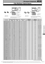
o Part Numbering<br />
<strong>Ceramic</strong> <strong>Trimmer</strong> <strong>Capacitors</strong><br />
(Part Number)<br />
TZ<br />
q<br />
Y2<br />
w<br />
R<br />
e<br />
200<br />
r<br />
A<br />
t<br />
001<br />
y<br />
R00<br />
u<br />
qProduct ID<br />
Product ID<br />
TZ<br />
wSeries/Terminal<br />
Code<br />
B4<br />
W4<br />
C3<br />
S2<br />
Y2<br />
V2<br />
R1<br />
<strong>Trimmer</strong> <strong>Capacitors</strong><br />
Series/Terminal<br />
4mm Size SMD Type<br />
4mm Size SMD Type<br />
3mm Size SMD Type<br />
2mm Size SMD Type (Height 1.0mm)<br />
2mm Size SMD Type (Height 1.25mm)<br />
2mm Size SMD Type (Height 1.45mm)<br />
1mm Size SMD Type (Height 0.90mm)<br />
tTerminal Shape<br />
Code<br />
Terminal Shape<br />
A<br />
B<br />
Top Adjustment: TZR1, TZS2, TZY2, TZV2,<br />
TZC3, TZW4, TZB4<br />
Top Adjustment: TZB4<br />
Please refer to dimensions for terminal details.<br />
yIndividual Specifications<br />
Code<br />
Individual Specifications<br />
001 TZR1, TZS2, TZY2, TZW4 Standard Type<br />
110<br />
TZV2, TZC3 Standard Type<br />
A10<br />
TZB4 No-cover Film Standard Type<br />
B10<br />
TZB4 with Cover Film Standard Type<br />
eTemperature Characteristics<br />
Code<br />
Temperature Characteristics<br />
Z<br />
NP0ppm/°C<br />
R<br />
N750ppm/°C<br />
K<br />
N1000ppm/°C<br />
P<br />
N1200ppm/°C<br />
Please refer to ratings for tolerance of temperature characteristics.<br />
uPackaging<br />
Code<br />
B00<br />
R00<br />
R01*<br />
* TZB4 only.<br />
Packaging<br />
Bulk<br />
Reel (Taping ø180mm)<br />
Reel (Taping ø330mm)<br />
rMaximum Capacitance<br />
Expressed by three-digit alphanumerics. The unit is pico-farad<br />
(pF). The first and second figures are significant digits, and the<br />
third figure expresses the number of zeros that follow the two<br />
numbers. If there is a decimal point, it is expressed by the capital<br />
letter "R". In this case, all figures are significant digits.<br />
2
!Note • Please read rating and !CAUTION (for storage, operating, rating, soldering, mounting and handling) in this catalog to prevent smoking and/or burning, etc.<br />
• This catalog has only typical specifications. Therefore, please approve our product specifi cations or transact the approval sheet for product specifi cations before ordering.<br />
T13E.pdf<br />
Nov.22,2013<br />
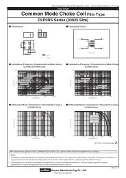
Selection Guide of <strong>Ceramic</strong> <strong>Trimmer</strong> <strong>Capacitors</strong><br />
Mounting Method<br />
Surface Mount<br />
Reflow<br />
Flow<br />
Height 0.90mm max.<br />
TZR1<br />
1.5(W) x 1.7(L)<br />
Height 1.7mm max.<br />
TZC3<br />
3.2(W) x 4.5(L)<br />
High Frequency Power<br />
Height 2.6mm max.<br />
Height 3.2mm max.<br />
TZB4_A<br />
4.0(W) x 4.5(L)<br />
(with cover film)<br />
Height 1.00mm max.<br />
TZS2<br />
2.2(W) x 2.7(L)<br />
Height 3.2mm max.<br />
TZB4_A<br />
4.0(W) x 4.5(L)<br />
TZW4<br />
4.2(W) x 5.2(L)<br />
TZB4_B<br />
4.0(W) x 4.5(L)<br />
(with cover film)<br />
Height 1.25mm max.<br />
TZY2<br />
2.5(W) x 3.2(L)<br />
TZB4_B<br />
4.0(W) x 4.5(L)<br />
Height 1.45mm max.<br />
TZV2<br />
2.3(W) x 3.2(L)<br />
All <strong>Ceramic</strong> <strong>Trimmer</strong> Capacitor products comply with RoHS and ELV.<br />
3
!Note • Please read rating and !CAUTION (for storage, operating, rating, soldering, mounting and handling) in this catalog to prevent smoking and/or burning, etc.<br />
• This catalog has only typical specifications. Therefore, please approve our product specifi cations or transact the approval sheet for product specifi cations before ordering.<br />
T13E.pdf<br />
Nov.22,2013<br />
1<br />
<strong>Ceramic</strong> <strong>Trimmer</strong> <strong>Capacitors</strong><br />
TZR1 Series<br />
c Features<br />
1. Ultra-small and thin with external dimensions<br />
of 1.5(W)x1.7(L)x0.85(H)mm<br />
(80% less in volume than the current product).<br />
2. Unique construction with no plastic material<br />
provides superior soldering heat resistance to<br />
maintain excellent characteristic performance<br />
after refl ow soldering.<br />
3. Suitable for high frequency circuit due to high<br />
self-resonant frequency (6.2GHz of TZR1Z010 at<br />
1.0pF setting).<br />
1.5<br />
0.45<br />
0.9 max.<br />
1.7<br />
0.2 (Depth;0.15)<br />
0.35<br />
( Tolerance: ±0.1 )<br />
in mm<br />
c Applications<br />
1. Bluetoothr<br />
2. Crystal oscillators<br />
3. Crystal fi lters<br />
4. Hand radios<br />
5. Miniature tuner packs (FM Radio, TV)<br />
6. Remote keyless entry systems<br />
7. Pagers<br />
Part Number<br />
C min. (max.)<br />
(pF)<br />
C max.<br />
(pF)<br />
TC Q Rated Voltage Withstanding Voltage<br />
TZR1Z010A001 0.55 1.0 +100/-0% NP0±300ppm/°C 200min. at 200MHz, Cmax. 25Vdc 55Vdc<br />
TZR1Z1R5A001 0.7 1.5 +100/-0% NP0±300ppm/°C 200min. at 200MHz, Cmax. 25Vdc 55Vdc<br />
TZR1Z040A001 1.5 4.0 +100/-0% NP0±500ppm/°C 300min. at 1MHz, Cmax. 25Vdc 55Vdc<br />
TZR1R080A001 3.0 8.0 +100/-0% N750±500ppm/°C 300min. at 1MHz, Cmax. 25Vdc 55Vdc<br />
Insulation Resistance: 10000M ohm Torque: 0.1 to 1.0mNm Operating Temperature Range: -25 to +85°C<br />
c Construction<br />
Cover<br />
Metal Rotor<br />
Monolithic<br />
Stator<br />
4
!Note • Please read rating and !CAUTION (for storage, operating, rating, soldering, mounting and handling) in this catalog to prevent smoking and/or burning, etc.<br />
• This catalog has only typical specifications. Therefore, please approve our product specifi cations or transact the approval sheet for product specifi cations before ordering.<br />
T13E.pdf<br />
Nov.22,2013<br />
c Temperature Characteristics<br />
TZR1Z010<br />
TZR1Z1R5<br />
1<br />
Z010 (NP0±300 ppm/°C)<br />
Z1R5 (NP0±300 ppm/°C)<br />
Cap. Change (%)<br />
+8<br />
+6<br />
+4<br />
+2<br />
0<br />
65 85<br />
Cap. Change (%)<br />
0<br />
+8<br />
+6<br />
+4<br />
+2<br />
65 85<br />
-25<br />
-10<br />
0<br />
-2<br />
-4<br />
-6<br />
20<br />
45<br />
Temp. (°C)<br />
-25<br />
-10<br />
0<br />
-2<br />
-4<br />
-6<br />
20<br />
45<br />
Temp. (°C)<br />
-8<br />
-8<br />
-10<br />
-10<br />
-12<br />
-12<br />
TZR1Z040<br />
Z040 (NP0±500 ppm/°C)<br />
TZR1R080<br />
R080 (N750±500 ppm/°C)<br />
–25<br />
–10<br />
0<br />
Cap.Change (%)<br />
+8<br />
+6<br />
+4<br />
+2<br />
0<br />
–2<br />
20<br />
–4<br />
–6<br />
–8<br />
–10<br />
45<br />
65 85<br />
Temp.(°C)<br />
–25<br />
–10<br />
0<br />
Cap.Change (%)<br />
+8<br />
+6<br />
+4<br />
+2<br />
20<br />
0<br />
–2<br />
–4<br />
–6<br />
–8<br />
–10<br />
Temp.(°C)<br />
45 65 85<br />
–12<br />
–12<br />
c Frequency Characteristics<br />
TZR1Z010<br />
Z010<br />
10000<br />
10000<br />
TZR1Z1R5<br />
Z1R5<br />
1000<br />
1000<br />
Q<br />
100<br />
0.55pF set<br />
Q<br />
100<br />
0.7pF set<br />
10<br />
10<br />
1.0pF set<br />
1.5pF set<br />
1<br />
1<br />
0<br />
0 2 4 6<br />
Frequency (GHz)<br />
8 10<br />
0<br />
0 2 4 6<br />
Frequency (GHz)<br />
8 10<br />
TZR1Z040<br />
Z040<br />
TZR1R080<br />
R080<br />
1000 1000<br />
1000 1000<br />
100<br />
100<br />
100<br />
100<br />
Q<br />
10<br />
10<br />
Capacitance (pF)<br />
Q<br />
10<br />
10<br />
Capacitance (pF)<br />
1<br />
500 1000 1500 2000 2500<br />
Frequency (MHz)<br />
1<br />
500 1000 1500 2000<br />
Frequency (MHz)<br />
5
!Note • Please read rating and !CAUTION (for storage, operating, rating, soldering, mounting and handling) in this catalog to prevent smoking and/or burning, etc.<br />
• This catalog has only typical specifications. Therefore, please approve our product specifi cations or transact the approval sheet for product specifi cations before ordering.<br />
T13E.pdf<br />
Nov.22,2013<br />
1<br />
c Land Pattern<br />
2.2<br />
1.2<br />
0.5<br />
Tolerance: ±0.1<br />
in mm<br />
c Temperature Profile<br />
Reflow Soldering Profile<br />
qSoldering profile for Lead-free solder (96.5Sn/3Ag/0.5Cu)<br />
Temperature (°C)<br />
T1<br />
T3<br />
T2<br />
t2<br />
t3<br />
T5<br />
T4<br />
Limit Profile<br />
Standard Profile<br />
wSoldering profile for Eutectic solder (63Sn/37Pb)<br />
(Limit profile: refer to q)<br />
Temperature (°C)<br />
T3<br />
T2<br />
T1<br />
t2<br />
Standard Profile<br />
t1<br />
time (s)<br />
t1<br />
time (s)<br />
Standard Profile<br />
Pre-heating Heating Peak<br />
temperature<br />
Temp. (T1) Time (t1) Temp. (T2) Time (t2) (T3)<br />
150 to 180°C 60 to 120sec. 220°C 30 to 60sec. 245±3°C<br />
Cycle<br />
of reflow<br />
2 times<br />
Standard Profile<br />
Pre-heating Heating Peak Cycle<br />
temperature<br />
Temp. (T1) Time (t1) Temp. (T2) Time (t2) (T3) of reflow<br />
150°C 60 to 120sec. 183°C 30sec. 230 +5/-0°C 1 time<br />
Limit Profile<br />
Pre-heating Heating Peak<br />
Cycle<br />
temperature<br />
Temp. (T1) Time (t1) Temp. (T4) Time (t3) (T5) of reflow<br />
150 to 180°C 60 to 120sec. 230°C 30 to 50sec. 260 +5/-0°C 2 times<br />
Soldering Iron<br />
Standard Profile<br />
Temperature of soldering iron tip Soldering time Soldering iron power output<br />
Cycle of soldering iron<br />
350±10°C 3sec. max. 30W max. 1 time<br />
c Notice (Storage and Operating Conditions)<br />
1. Do not use the trimmer capacitor under atmosphere<br />
of RTV silicone rubber (Room Temperature<br />
Vulcanizing Silicone Rubber) except Acetone<br />
liberating silicone sealant.<br />
2. Before using trimmer capacitors, please store under<br />
the conditions of -10 to +40°C and 30 to 85%RH.<br />
3. Do not store in or near corrosive gasses.<br />
4. Use within 6 months of delivery.<br />
5. Do not store under direct sunlight.<br />
6. Do not use the trimmer capacitor under the<br />
conditions listed below.<br />
(1) Corrosive gasses atmosphere<br />
(ex. Chlorine gas, Hydrogen sulfi de gas,<br />
Ammonia gas, Sulfuric acid gas, Nitric oxide gas,<br />
etc.)<br />
(2) In liquid (ex. water, oil, medical liquid,<br />
organic solvent, etc.)<br />
(3) Dusty / dirty atmosphere<br />
(4) Direct sunlight<br />
(5) Static voltage or electric/magnetic fi elds<br />
(6) Direct sea breeze<br />
(7) Other variations of the above<br />
6
!Note • Please read rating and !CAUTION (for storage, operating, rating, soldering, mounting and handling) in this catalog to prevent smoking and/or burning, etc.<br />
• This catalog has only typical specifications. Therefore, please approve our product specifi cations or transact the approval sheet for product specifi cations before ordering.<br />
T13E.pdf<br />
Nov.22,2013<br />
c Notice (Soldering and Mounting)<br />
1. Soldering<br />
(1) TZR1 series can be soldered by refl ow soldering<br />
method and soldering iron. Do not use fl ow<br />
soldering method (dipping).<br />
(2) Soldering conditions<br />
Refer to the temperature profi le.<br />
If the soldering conditions are not suitable, e.g.,<br />
excessive time and/or excessive temperature, the<br />
trimmer capacitor may deviate from the specifi ed<br />
characteristics.<br />
(3) The amount of solder is critical.<br />
(4) The thickness of solder paste should be printed<br />
from 100 micro m to 150 micro m and the dimension<br />
of land pattern should be <strong>Murata</strong>'s standard land<br />
pattern used at refl ow soldering.<br />
Insuffi cient amounts of solder can lead to<br />
insuffi cient soldering strength on PCB.<br />
Excessive amounts of solder may cause bridging<br />
between the terminals or contact failure due to<br />
fl ux wicking up.<br />
(5) When using soldering iron, the diameter of the<br />
string solder shall be less than 0.5mm. The<br />
string solder shall be applied to the lower<br />
part of the terminal only. Do not apply fl ux<br />
except to the terminals. Excessive amounts of<br />
solder and/or applying solder to the upper part<br />
of the terminal may cause fi xed metal rotor or<br />
contact failure due to fl ux invasion into<br />
the movable part and/or the contact point. The<br />
soldering iron should not come in contact with<br />
the monolithic stator of the trimmer capacitor.<br />
If such contact does occur, the trimmer<br />
capacitor may be damaged.<br />
(6) Our recommended chlorine content of solder is<br />
as follows.<br />
(a) Solder paste: 0.2wt% max.<br />
(b) String solder: 0.5wt% max.<br />
(7) Do not use water-soluble fl ux (for water<br />
cleaning). To prevent the deterioration of<br />
trimmer capacitor characteristics, apply fl ux<br />
only to terminals.<br />
2. Mounting<br />
(1) Do not apply excessive force (preferably 5.0 N<br />
[Ref: 500gf] max.), when the trimmer capacitor<br />
is mounted on the PCB.<br />
(2) Do not warp and/or bend PCB to protect trimmer<br />
capacitor from breaking.<br />
(3) Use a pick-up nozzle of a suitable dimension.<br />
(1.6mm external diameter and 0.8mm bore<br />
diameter.)<br />
3. Cleaning<br />
This product cannot be cleaned because of open<br />
construction.<br />
4. Other<br />
Note the polarity of the trimmer capacitor to<br />
minimize infl uence by stray capacitance.<br />
(Refer to the dimensions concerning the polarity.)<br />
1<br />
c Notice (Handling)<br />
1. Use suitable screwdrivers that fi t comfortably in<br />
driver slot.<br />
*Recommended screwdriver for manual adjustment<br />
MURATA: KMDR160<br />
2. When adjusting with a screwdriver, do not apply<br />
excessive force (preferably 0.5 N [Ref: 50gf] max.)<br />
to minimize capacitance drift. Excessive force applied<br />
to the screwdriver slot may cause deformation of the<br />
products.<br />
3. Do not apply adhesive, lock paints, or any other<br />
substances to the trimmer capacitor to secure the<br />
rotor position. They may cause corrosion or<br />
electrical contact problems.<br />
c Notice (Other)<br />
Before using trimmer capacitors, please test after<br />
assembly in your particular mass production system.<br />
7
!Note • Please read rating and !CAUTION (for storage, operating, rating, soldering, mounting and handling) in this catalog to prevent smoking and/or burning, etc.<br />
• This catalog has only typical specifications. Therefore, please approve our product specifi cations or transact the approval sheet for product specifi cations before ordering.<br />
T13E.pdf<br />
Nov.22,2013<br />
<strong>Ceramic</strong> <strong>Trimmer</strong> <strong>Capacitors</strong><br />
TZS2 Series<br />
2.7<br />
2 c Features<br />
1. Ultra-small and thin type with external dimensions<br />
of 2.2(W)x2.7(L)x0.95(H)mm<br />
(30% less in volume than the current product).<br />
2. Unique construction with no plastic material<br />
provides superior soldering heat resistance to<br />
maintain excellent characteristic performance<br />
after refl ow soldering.<br />
3. Pierced square hole allows for high resistance to<br />
tuning force and in-process automatic adjustment.<br />
1.0max. 2.2<br />
0.6<br />
0.20 Depth<br />
1.0<br />
0.4<br />
Tolerance: ±0.1<br />
in mm<br />
c Applications<br />
1. Crystal oscillators 8. Remote keyless entry systems<br />
2. Crystal fi lters 9. PHS<br />
3. Hand radios 10. Radar detectors<br />
4. Cordless telephones 11. W-LAN<br />
5. Cellular telephones 12. Compact radios<br />
6. Tuner packs 13. Headphone stereos<br />
7. Pagers<br />
Part Number<br />
C min. (max.)<br />
(pF)<br />
C max.<br />
(pF)<br />
TC Q Rated Voltage Withstanding Voltage<br />
TZS2Z060A001 3.0 6.0 +100/-0% NP0±300ppm/°C 500min. at 1MHz, Cmax. 25Vdc 55Vdc<br />
TZS2Z100A001 3.5 10.0 +100/-0% NP0±300ppm/°C 500min. at 1MHz, Cmax. 25Vdc 55Vdc<br />
TZS2R200A001 7.0 20.0 +100/-0% N750±500ppm/°C 500min. at 1MHz, Cmax. 25Vdc 55Vdc<br />
Insulation Resistance: 10000M ohm Torque: 0.7 to 4.9mNm Operating Temperature Range: -25 to +85°C<br />
c Construction<br />
Cover<br />
Metal Rotor<br />
Monolithic<br />
Stator<br />
8
!Note • Please read rating and !CAUTION (for storage, operating, rating, soldering, mounting and handling) in this catalog to prevent smoking and/or burning, etc.<br />
• This catalog has only typical specifications. Therefore, please approve our product specifi cations or transact the approval sheet for product specifi cations before ordering.<br />
T13E.pdf<br />
Nov.22,2013<br />
c Temperature Characteristics<br />
TZS2Z060<br />
TZS2Z100<br />
Z060 (NP0±300 ppm/°C)<br />
Z100 (NP0±300 ppm/°C)<br />
Cap.Change (%)<br />
+8<br />
+6<br />
+4<br />
+2<br />
0<br />
65 85<br />
Cap.Change (%)<br />
+8<br />
+6<br />
+4<br />
+2<br />
0<br />
Temp.(°C)<br />
2<br />
–25<br />
–10<br />
0<br />
–2<br />
–4<br />
–6<br />
–8<br />
–10<br />
–12<br />
20<br />
45<br />
Temp.(°C)<br />
–25<br />
–10<br />
0<br />
–2<br />
–4<br />
–6<br />
–8<br />
–10<br />
–12<br />
20<br />
45<br />
65 85<br />
TZS2R200<br />
R200 (N750±500 ppm/°C)<br />
–25<br />
–10<br />
0<br />
Cap.Change (%)<br />
+8<br />
+6<br />
+4<br />
+2<br />
20<br />
0<br />
–2<br />
Temp.(°C)<br />
45 65 85<br />
–4<br />
–6<br />
–8<br />
–10<br />
–12<br />
c Frequency Characteristics<br />
TZS2Z060<br />
TZS2Z100<br />
Z060<br />
Z100<br />
1000<br />
1000<br />
1000<br />
1000<br />
100<br />
100<br />
100<br />
100<br />
Q<br />
10<br />
10<br />
Capacitance (pF)<br />
Q<br />
10<br />
10<br />
Capacitance (pF)<br />
1<br />
500 1000 1500 2000<br />
1<br />
200 400 600 800 1000<br />
Frequency (MHz)<br />
Frequency (MHz)<br />
Continued on the following page.<br />
9
!Note • Please read rating and !CAUTION (for storage, operating, rating, soldering, mounting and handling) in this catalog to prevent smoking and/or burning, etc.<br />
• This catalog has only typical specifications. Therefore, please approve our product specifi cations or transact the approval sheet for product specifi cations before ordering.<br />
Continued from the preceding page.<br />
c Frequency Characteristics<br />
TZS2R200<br />
T13E.pdf<br />
Nov.22,2013<br />
R200<br />
1000<br />
1000<br />
2<br />
100<br />
100<br />
Q<br />
10<br />
10<br />
Capacitance (pF)<br />
1<br />
200 400 600 800 1000<br />
Frequency (MHz)<br />
c Land Pattern<br />
3.2<br />
2.1<br />
1.0<br />
Tolerance: ±0.1<br />
in mm<br />
c Temperature Profile<br />
Reflow Soldering Profile<br />
qSoldering profile for Lead-free solder (96.5Sn/3Ag/0.5Cu)<br />
Temperature (°C)<br />
T1<br />
T3<br />
T2<br />
t2<br />
t3<br />
T5<br />
T4<br />
Limit Profile<br />
Standard Profile<br />
wSoldering profile for Eutectic solder (63Sn/37Pb)<br />
(Limit profile: refer to q)<br />
Temperature (°C)<br />
T3<br />
T2<br />
T1<br />
t2<br />
Standard Profile<br />
t1<br />
time (s)<br />
t1<br />
time (s)<br />
Standard Profile<br />
Pre-heating Heating Peak<br />
temperature<br />
Temp. (T1) Time (t1) Temp. (T2) Time (t2) (T3)<br />
150 to 180°C 60 to 120sec. 220°C 30 to 60sec. 245±3°C<br />
Cycle<br />
of reflow<br />
2 times<br />
Standard Profile<br />
Pre-heating Heating Peak Cycle<br />
temperature<br />
Temp. (T1) Time (t1) Temp. (T2) Time (t2) (T3) of reflow<br />
150°C 60 to 120sec. 183°C 30sec. 230 +5/-0°C 1 time<br />
Limit Profile<br />
Pre-heating Heating Peak<br />
Cycle<br />
temperature<br />
Temp. (T1) Time (t1) Temp. (T4) Time (t3) (T5) of reflow<br />
150 to 180°C 60 to 120sec. 230°C 30 to 50sec. 260 +5/-0°C 2 times<br />
Soldering Iron<br />
Standard Profile<br />
Temperature of soldering iron tip Soldering time Soldering iron power output<br />
Cycle of soldering iron<br />
350±10°C 3sec. max. 30W max. 1 time<br />
10
!Note • Please read rating and !CAUTION (for storage, operating, rating, soldering, mounting and handling) in this catalog to prevent smoking and/or burning, etc.<br />
• This catalog has only typical specifications. Therefore, please approve our product specifi cations or transact the approval sheet for product specifi cations before ordering.<br />
T13E.pdf<br />
Nov.22,2013<br />
c Notice (Storage and Operating Conditions)<br />
1. Do not use the trimmer capacitor under atmosphere<br />
of RTV silicone rubber (Room Temperature<br />
Vulcanizing Silicone Rubber) except Acetone<br />
liberating silicone sealant.<br />
2. Before using trimmer capacitors, please store under<br />
the conditions of -10 to +40°C and 30 to 85%RH.<br />
3. Do not store in or near corrosive gasses.<br />
4. Use within 6 months of delivery.<br />
5. Do not store under direct sunlight.<br />
c Notice (Soldering and Mounting)<br />
1. Soldering<br />
(1) TZS2 series can be soldered by refl ow soldering<br />
method and soldering iron. Do not use fl ow<br />
soldering method (dipping).<br />
(2) Soldering conditions<br />
Refer to the temperature profi le.<br />
If the soldering conditions are not suitable, e.g.,<br />
excessive time and/or excessive temperature,<br />
the trimmer capacitor may deviate from the<br />
specifi ed characteristics.<br />
(3) The amount of solder is critical.<br />
(4) The thickness of solder paste should be printed<br />
from 100 micro m to 150 micro m and the dimension<br />
of land pattern should be <strong>Murata</strong>'s standard land<br />
pattern used at refl ow soldering.<br />
Insuffi cient amounts of solder can lead to<br />
insuffi cient soldering strength on PCB.<br />
Excessive amounts of solder may cause bridging<br />
between the terminals or contact failure due to<br />
fl ux wicking up.<br />
(5) When using soldering iron, the diameter of the<br />
string solder shall be less than 0.5mm. The<br />
string solder shall be applied to the lower part<br />
of the terminal only. Do not apply fl ux except<br />
to the terminals. Excessive amounts of solder<br />
and/or applying solder to the upper part of the<br />
terminal may cause fi xed metal rotor or contact<br />
failure due to fl ux invasion into the movable<br />
c Notice (Handling)<br />
1. Use suitable screwdrivers that fi t comfortably in<br />
driver slot.<br />
(1) Recommended screwdriver for manual adjustment<br />
MURATA: KMDR050<br />
(2) Recommended screwdriver bit for automatic<br />
adjustment<br />
MURATA: KMBT050<br />
c Notice (Other)<br />
Before using trimmer capacitors, please test after<br />
assembly in your particular mass production system.<br />
6. Do not use the trimmer capacitor under the<br />
conditions listed below.<br />
(1) Corrosive gasses atmosphere<br />
(ex. Chlorine gas, Hydrogen sulfi de gas,<br />
Ammonia gas, Sulfuric acid gas, Nitric oxide gas,<br />
etc.)<br />
(2) In liquid (ex. water, oil, medical liquid,<br />
organic solvent, etc.)<br />
(3) Dusty / dirty atmosphere<br />
(4) Direct sunlight<br />
(5) Static voltage or electric/magnetic fi elds<br />
(6) Direct sea breeze<br />
(7) Other variations of the above<br />
part and/or the contact point. The soldering<br />
iron should not come in contact with the<br />
monolithic stator of the trimmer capacitor.<br />
If such contact does occur, the trimmer<br />
capacitor may be damaged.<br />
(6) Our recommended chlorine content of solder is<br />
as follows.<br />
(a) Solder paste: 0.2wt% max.<br />
(b) String solder: 0.5wt% max.<br />
(7) Do not use water-soluble fl ux (for water<br />
cleaning). To prevent the deterioration of<br />
trimmer capacitor characteristics, apply fl ux<br />
only to terminals.<br />
2. Mounting<br />
(1) Do not apply excessive force (preferably 5.0 N<br />
[Ref: 500gf] max.), when the trimmer capacitor<br />
is mounted on the PCB.<br />
(2) Do not warp and/or bend PCB to protect trimmer<br />
capacitor from breakage.<br />
(3) Use a pick-up nozzle of a suitable dimension.<br />
(2.0mm external diameter and 1.0mm bore diameter.)<br />
3. Cleaning<br />
This product cannot be cleaned because of open<br />
construction.<br />
4. Other<br />
Note the polarity of the trimmer capacitor to<br />
minimize infl uence by stray capacitance.<br />
(Refer to the dimensions concerning the polarity.)<br />
2. When adjusting with a screwdriver, do not apply<br />
excessive force (preferably 1.0 N [Ref: 100gf] max.)<br />
to minimize capacitance drift. Excessive force applied<br />
to the screwdriver slot may cause deformation of the<br />
products.<br />
3. Do not apply adhesive, lock paints, or any other<br />
substances to the trimmer capacitor to secure the<br />
rotor position. They may cause corrosion or<br />
electrical contact problems.<br />
2<br />
11
!Note • Please read rating and !CAUTION (for storage, operating, rating, soldering, mounting and handling) in this catalog to prevent smoking and/or burning, etc.<br />
• This catalog has only typical specifications. Therefore, please approve our product specifi cations or transact the approval sheet for product specifi cations before ordering.<br />
T13E.pdf<br />
Nov.22,2013<br />
<strong>Ceramic</strong> <strong>Trimmer</strong> <strong>Capacitors</strong><br />
TZY2 Series<br />
3.2±0.2<br />
3<br />
c Features<br />
1. Small and thin size with external dimensions<br />
of 2.5(W)x3.2(L)x1.25max.(H)mm.<br />
2. New shape of cover can improve the fl ux invasion<br />
compared with current products.<br />
3. Improvement of the adhesion between rotor and<br />
stator leads to superior stability.<br />
4. Unique construction with no plastic material<br />
provides superior soldering heat resistance to<br />
maintain excellent characteristic performance<br />
after refl ow soldering.<br />
5. Suitable for high frequency circuit due to high<br />
self-resonant frequency (4.8GHz of TZY2Z010 at<br />
1.0pF setting).<br />
2.5±0.2<br />
1.4<br />
1.25max. 0.95<br />
0.45<br />
1.0<br />
0.5<br />
( Tolerance: ±0.1 )<br />
in mm<br />
c Applications<br />
1. Crystal oscillators 9. Remote keyless entry systems<br />
2. Crystal fi lters 10. W-LAN<br />
3. Pagers 11. Radar detectors<br />
4. Cordless telephones 12. Compact radios<br />
5. PHS 13. DVD<br />
6. Hand radios 14. Burglarproof devices<br />
7. Cellular telephones 15. Headphone stereos<br />
8. Watches<br />
Part Number<br />
C min. (max.)<br />
(pF)<br />
C max.<br />
(pF)<br />
TC Q Rated Voltage Withstanding Voltage<br />
TZY2Z010A001 0.5 1.0 +100/-0% NP0±300ppm/°C 200min. at 200MHz, Cmax. 25Vdc 55Vdc<br />
TZY2Z2R5A001 0.65 2.5 +100/-0% NP0±300ppm/°C 200min. at 200MHz, Cmax. 25Vdc 55Vdc<br />
TZY2Z030A001 1.5 3.0 +100/-0% NP0±300ppm/°C 300min. at 1MHz, Cmax. 25Vdc 55Vdc<br />
TZY2Z060A001 2.5 6.0 +100/-0% NP0±300ppm/°C 500min. at 1MHz, Cmax. 25Vdc 55Vdc<br />
TZY2Z100A001 3.0 10.0 +100/-0% NP0±300ppm/°C 500min. at 1MHz, Cmax. 25Vdc 55Vdc<br />
TZY2R200A001 4.5 20.0 +100/-0% N750±500ppm/°C 500min. at 1MHz, Cmax. 25Vdc 55Vdc<br />
TZY2R250A001 5.5 25.0 +100/-0% N750±500ppm/°C 300min. at 1MHz, Cmax. 25Vdc 55Vdc<br />
TZY2K450A001 8.0 45.0 +100/-0% N1000±500ppm/°C 300min. at 1MHz, Cmax. 25Vdc 55Vdc<br />
Insulation Resistance: 10000M ohm Torque: 0.7 to 4.9mNm Operating Temperature Range: -25 to +85°C<br />
c Construction<br />
Cover<br />
Metal Rotor<br />
Monolithic<br />
Stator<br />
12
!Note • Please read rating and !CAUTION (for storage, operating, rating, soldering, mounting and handling) in this catalog to prevent smoking and/or burning, etc.<br />
• This catalog has only typical specifications. Therefore, please approve our product specifi cations or transact the approval sheet for product specifi cations before ordering.<br />
T13E.pdf<br />
Nov.22,2013<br />
c Temperature Characteristics<br />
TZY2Z010<br />
TZY2Z100<br />
Z010 (NP0±300 ppm/°C)<br />
Z100 (NP0±300 ppm/°C)<br />
-25<br />
-10<br />
0<br />
Cap. Change (%)<br />
+8<br />
+6<br />
+4<br />
+2<br />
0<br />
-2<br />
20<br />
-4<br />
-6<br />
-8<br />
-10<br />
-12<br />
45<br />
65 85<br />
Temp. (°C)<br />
–25<br />
–10<br />
0<br />
Cap.Change (%)<br />
+8<br />
+6<br />
+4<br />
+2<br />
0<br />
20<br />
–2<br />
–4<br />
–6<br />
–8<br />
–10<br />
–12<br />
45<br />
Temp.(°C)<br />
65 85<br />
3<br />
TZY2R200<br />
TZY2K450<br />
R200 (N750±500 ppm/°C)<br />
K450 (N1000±500ppm/°C)<br />
–25<br />
–10<br />
0<br />
Cap.Change (%)<br />
+8<br />
+6<br />
+4<br />
+2<br />
20<br />
0<br />
–2<br />
–4<br />
–6<br />
–8<br />
–10<br />
–12<br />
Temp.(°C)<br />
45 65 85<br />
25<br />
0<br />
+12<br />
+10<br />
+8<br />
+6<br />
+4<br />
+2<br />
20<br />
0<br />
–2<br />
–4<br />
–6<br />
–8<br />
–10<br />
–12<br />
Cap. Change (%)<br />
45<br />
Temp. (°C)<br />
65 85<br />
c Frequency Characteristics<br />
TZY2Z010<br />
TZY2Z100<br />
Z010<br />
Z100<br />
1000<br />
1000<br />
1000<br />
100<br />
100<br />
100<br />
Q<br />
10<br />
1.0pF set<br />
0.5pF set<br />
Q<br />
10<br />
10<br />
Capacitance (pF)<br />
1<br />
0 2 4 6<br />
8<br />
1<br />
200 400 600 800 1000<br />
Frequency (GHz)<br />
Frequency (MHz)<br />
Continued on the following page.<br />
13
!Note • Please read rating and !CAUTION (for storage, operating, rating, soldering, mounting and handling) in this catalog to prevent smoking and/or burning, etc.<br />
• This catalog has only typical specifications. Therefore, please approve our product specifi cations or transact the approval sheet for product specifi cations before ordering.<br />
Continued from the preceding page.<br />
c Frequency Characteristics<br />
TZY2R200<br />
TZY2K450<br />
T13E.pdf<br />
Nov.22,2013<br />
R200<br />
K450<br />
1000<br />
1000<br />
1000<br />
1000<br />
3<br />
Q<br />
100<br />
10<br />
100<br />
10<br />
Capacitance (pF)<br />
Q<br />
100<br />
10<br />
100<br />
10<br />
Capacitance (pF)<br />
1<br />
200 400 600 800 1000<br />
1<br />
200<br />
400 600 800<br />
Frequency (MHz)<br />
Frequency (MHz)<br />
c Land Pattern<br />
4.0<br />
2.4<br />
1.2<br />
Tolerance: ±0.1<br />
in mm<br />
c Temperature Profile<br />
Reflow Soldering Profile<br />
qSoldering profile for Lead-free solder (96.5Sn/3Ag/0.5Cu)<br />
Temperature (°C)<br />
T1<br />
T3<br />
T2<br />
t2<br />
t3<br />
T5<br />
T4<br />
Limit Profile<br />
Standard Profile<br />
wSoldering profile for Eutectic solder (63Sn/37Pb)<br />
(Limit profile: refer to q)<br />
Temperature (°C)<br />
T3<br />
T2<br />
T1<br />
t2<br />
Standard Profile<br />
t1<br />
time (s)<br />
t1<br />
time (s)<br />
Standard Profile<br />
Pre-heating Heating Peak<br />
temperature<br />
Temp. (T1) Time (t1) Temp. (T2) Time (t2) (T3)<br />
150 to 180°C 60 to 120sec. 220°C 30 to 60sec. 245±3°C<br />
Cycle<br />
of reflow<br />
2 times<br />
Standard Profile<br />
Pre-heating Heating Peak Cycle<br />
temperature<br />
Temp. (T1) Time (t1) Temp. (T2) Time (t2) (T3) of reflow<br />
150°C 60 to 120sec. 183°C 30sec. 230 +5/-0°C 1 time<br />
Limit Profile<br />
Pre-heating Heating Peak<br />
Cycle<br />
temperature<br />
Temp. (T1) Time (t1) Temp. (T4) Time (t3) (T5) of reflow<br />
150 to 180°C 60 to 120sec. 230°C 30 to 50sec. 260 +5/-0°C 2 times<br />
Soldering Iron<br />
Standard Profile<br />
Temperature of soldering iron tip Soldering time Soldering iron power output<br />
Cycle of soldering iron<br />
350±10°C 3sec. max. 30W max. 1 time<br />
14
!Note • Please read rating and !CAUTION (for storage, operating, rating, soldering, mounting and handling) in this catalog to prevent smoking and/or burning, etc.<br />
• This catalog has only typical specifications. Therefore, please approve our product specifi cations or transact the approval sheet for product specifi cations before ordering.<br />
T13E.pdf<br />
Nov.22,2013<br />
c Notice (Storage and Operating Conditions)<br />
1. Do not use the trimmer capacitor under atmosphere<br />
of RTV silicone rubber (Room Temperature<br />
Vulcanizing Silicone Rubber) except Acetone<br />
liberating silicone sealant.<br />
2. Before using trimmer capacitors, please store under<br />
the conditions of -10 to +40°C and 30 to 85%RH.<br />
3. Do not store in or near corrosive gasses.<br />
4. Use within 6 months of delivery.<br />
5. Do not store under direct sunlight.<br />
c Notice (Soldering and Mounting)<br />
1. Soldering<br />
(1) TZY2 series can be soldered by refl ow soldering<br />
method and soldering iron. Do not use fl ow<br />
soldering method (dipping).<br />
(2) Soldering conditions<br />
Refer to the temperature profi le.<br />
If the soldering conditions are not suitable, e.g.,<br />
excessive time and/or excessive temperature, the<br />
trimmer capacitor may deviate from the specifi ed<br />
characteristics.<br />
(3) The amount of solder is critical.<br />
(4) The thickness of solder paste should be printed<br />
from 120 micro m to 170 micro m and the dimension<br />
of land pattern should be <strong>Murata</strong>'s standard land<br />
pattern used at refl ow soldering.<br />
Insuffi cient amounts of solder can lead to<br />
insuffi cient soldering strength on PCB.<br />
Excessive amounts of solder may cause bridging<br />
between the terminals or contact failure due to<br />
fl ux wicking up.<br />
(5) When using soldering iron, the diameter of the<br />
string solder shall be less than 0.5mm. The<br />
string solder shall be applied to the lower<br />
part of the terminal only. Do not apply fl ux<br />
except to the terminals. Excessive amounts of<br />
solder and/or applying solder to the upper part<br />
of the terminal may cause fi xed metal rotor or<br />
contact failure due to fl ux invasion into<br />
c Notice (Handling)<br />
1. Use suitable screwdrivers that fi t comfortably in<br />
driver slot.<br />
(1) Recommended screwdriver for manual adjustment<br />
ENGINEER INC.: DA-89<br />
(<strong>Murata</strong> P/N is KMDR060)<br />
(2) Recommended screwdriver bit for automatic<br />
adjustment<br />
MURATA: KMBT060<br />
c Notice (Other)<br />
Before using trimmer capacitor, please test after<br />
assembly in your particular mass production system.<br />
6. Do not use the trimmer capacitor under the<br />
conditions listed below.<br />
(1) Corrosive gasses atmosphere<br />
(ex. Chlorine gas, Hydrogen sulfi de gas,<br />
Ammonia gas, Sulfuric acid gas, Nitric oxide gas,<br />
etc.)<br />
(2) In liquid (ex. water, oil, medical liquid,<br />
organic solvent, etc.)<br />
(3) Dusty / dirty atmosphere<br />
(4) Direct sunlight<br />
(5) Static voltage or electric/magnetic fi elds<br />
(6) Direct sea breeze<br />
(7) Other variations of the above<br />
the movable part and/or the contact point. The<br />
soldering iron should not come in contact with<br />
the monolithic stator of the trimmer capacitor.<br />
If such contact does occur, the trimmer<br />
capacitor may be damaged.<br />
(6) Our recommended chlorine content of solder is<br />
as follows.<br />
(a) Solder paste: 0.2wt% max.<br />
(b) String solder: 0.5wt% max.<br />
(7) Do not use water-soluble fl ux (for water<br />
cleaning). To prevent the deterioration of<br />
trimmer capacitor characteristics, apply fl ux<br />
only to terminals.<br />
2. Mounting<br />
(1) Do not apply excessive force (preferably 5.0 N<br />
[Ref: 500gf] max.), when the trimmer capacitor<br />
is mounted on the PCB.<br />
(2) Do not warp and/or bend PCB to protect trimmer<br />
capacitor from breakage.<br />
(3) Use a pick-up nozzle of a suitable dimension.<br />
(2.5mm external diameter and 1.2mm bore diameter.)<br />
3. Cleaning<br />
This product cannot be cleaned because of open<br />
construction.<br />
4. Other<br />
Note the polarity of the trimmer capacitor to<br />
minimize infl uence by stray capacitance.<br />
(Refer to the dimensions concerning the polarity.)<br />
2. When adjusting with a screwdriver, do not apply<br />
excessive force (preferably 1.0 N [Ref: 100gf] max.)<br />
to minimize capacitance drift. Excessive force applied<br />
to the screwdriver slot may cause deformation of the<br />
products.<br />
3. Do not apply adhesive, lock paints, or any other<br />
substances to the trimmer capacitor to secure the<br />
rotor position. They may cause corrosion or<br />
electrical contact problems.<br />
3<br />
15
!Note • Please read rating and !CAUTION (for storage, operating, rating, soldering, mounting and handling) in this catalog to prevent smoking and/or burning, etc.<br />
• This catalog has only typical specifications. Therefore, please approve our product specifi cations or transact the approval sheet for product specifi cations before ordering.<br />
T13E.pdf<br />
Nov.22,2013<br />
<strong>Ceramic</strong> <strong>Trimmer</strong> <strong>Capacitors</strong><br />
TZV2 Series<br />
c Features<br />
1. Small size with external dimensions of<br />
2.3(W)x3.2(L)x1.45max.(H)mm.<br />
2. Unique construction with no plastic material<br />
provides superior soldering heat resistance to<br />
maintain excellent characteristic performance after<br />
refl ow soldering.<br />
3. Designed for automatic placement in surface mount<br />
applications.<br />
4. Funnel shaped metal case enables in-process<br />
automatic adjustment.<br />
2.3±0.2<br />
1.45max.<br />
1.4<br />
3.2±0.2<br />
0.5 Depth 0.2<br />
1.0<br />
Marking(10pF)<br />
Marking(6pF)<br />
Tolerance: ±0.1<br />
in mm<br />
4<br />
c Applications<br />
1. Crystal oscillator 9. PHS<br />
2. Crystal fi lters 10. Radar detectors<br />
3. Hand radios 11. W-LAN<br />
4. Cordless telephones 12. Compact radios<br />
5. Cellular telephones 13. Headphone stereos<br />
6. Tuner packs 14. DVD<br />
7. Pagers 15. Burglarproof devices<br />
8. Remote keyless entry systems<br />
Part Number<br />
C min. (max.)<br />
(pF)<br />
C max.<br />
(pF)<br />
TC Q Rated Voltage Withstanding Voltage<br />
TZV2Z2R5A110 0.65 2.5 +100/-0% NP0±300ppm/°C 200min. at 200MHz, Cmax. 25Vdc 55Vdc<br />
TZV2Z030A110 1.5 3.0 +100/-0% NP0±300ppm/°C 300min. at 1MHz, Cmax. 25Vdc 55Vdc<br />
TZV2Z060A110 2.5 6.0 +100/-0% NP0±300ppm/°C 500min. at 1MHz, Cmax. 25Vdc 55Vdc<br />
TZV2Z100A110 3.0 10.0 +100/-0% NP0±300ppm/°C 500min. at 1MHz, Cmax. 25Vdc 55Vdc<br />
TZV2R200A110 4.5 20.0 +100/-0% N750±500ppm/°C 500min. at 1MHz, Cmax. 25Vdc 55Vdc<br />
Insulation Resistance: 10000M ohm Torque: 1.0 to 9.8mNm Operating Temperature Range: -25 to +85°C<br />
c Construction<br />
Cover<br />
Spring Washer<br />
Metal Rotor<br />
Monolithic Stator<br />
16
!Note • Please read rating and !CAUTION (for storage, operating, rating, soldering, mounting and handling) in this catalog to prevent smoking and/or burning, etc.<br />
• This catalog has only typical specifications. Therefore, please approve our product specifi cations or transact the approval sheet for product specifi cations before ordering.<br />
T13E.pdf<br />
Nov.22,2013<br />
c Temperature Characteristics<br />
TZV2Z2R5<br />
Z2R5 (NP0±300 ppm/°C)<br />
TZV2Z060<br />
Z060 (NP0±300 ppm/°C)<br />
–25<br />
–10<br />
0<br />
Cap.Change (%)<br />
+8<br />
+6<br />
+4<br />
+2<br />
0<br />
–2<br />
20<br />
–4<br />
–6<br />
–8<br />
–10<br />
–12<br />
45<br />
Temp.(°C)<br />
65 85<br />
–25<br />
–10<br />
0<br />
Cap.Change (%)<br />
+8<br />
+6<br />
+4<br />
+2<br />
0<br />
–2<br />
20<br />
–4<br />
–6<br />
–8<br />
–10<br />
–12<br />
45<br />
65 85<br />
Temp.(°C)<br />
TZV2Z100<br />
Z100 (NP0±300 ppm/°C)<br />
TZV2R200<br />
R200 (N750±500 ppm/°C)<br />
–25<br />
–10<br />
0<br />
Cap.Change (%)<br />
+8<br />
+6<br />
+4<br />
+2<br />
0<br />
20<br />
–2<br />
–4<br />
–6<br />
–8<br />
–10<br />
–12<br />
45<br />
Temp.(°C)<br />
65 85<br />
–25<br />
–10<br />
0<br />
Cap.Change (%)<br />
+8<br />
+6<br />
+4<br />
+2<br />
20<br />
0<br />
–2<br />
–4<br />
–6<br />
–8<br />
–10<br />
–12<br />
Temp.(°C)<br />
45 65 85<br />
4<br />
c Frequency Characteristics<br />
TZV2Z2R5<br />
TZV2Z060<br />
Z2R5<br />
Z060<br />
1000<br />
1000<br />
1000<br />
1000<br />
100<br />
100<br />
100<br />
100<br />
Q<br />
10<br />
10<br />
Capacitance (pF)<br />
Q<br />
10<br />
10<br />
Capacitance (pF)<br />
1<br />
500 1000 1500 2000 2500 3000<br />
1<br />
500 1000 1500 2000<br />
Frequency (MHz)<br />
Frequency (MHz)<br />
Continued on the following page.<br />
17
!Note • Please read rating and !CAUTION (for storage, operating, rating, soldering, mounting and handling) in this catalog to prevent smoking and/or burning, etc.<br />
• This catalog has only typical specifications. Therefore, please approve our product specifi cations or transact the approval sheet for product specifi cations before ordering.<br />
Continued from the preceding page.<br />
c Frequency Characteristics<br />
TZV2Z100<br />
TZV2R200<br />
T13E.pdf<br />
Nov.22,2013<br />
Z100<br />
R200<br />
1000<br />
1000<br />
1000<br />
1000<br />
100<br />
100<br />
100<br />
100<br />
Q<br />
10<br />
10<br />
Capacitance (pF)<br />
Q<br />
10<br />
10<br />
Capacitance (pF)<br />
1<br />
200 400 600 800 1000<br />
1<br />
200 400 600 800 1000<br />
Frequency (MHz)<br />
Frequency (MHz)<br />
4<br />
c Land Pattern<br />
4.0<br />
2.4<br />
1.2<br />
Tolerance: ±0.1<br />
in mm<br />
c Temperature Profile<br />
Reflow Soldering Profile<br />
qSoldering profile for Lead-free solder (96.5Sn/3Ag/0.5Cu)<br />
Temperature (°C)<br />
T1<br />
T3<br />
T2<br />
t2<br />
t3<br />
T5<br />
T4<br />
Limit Profile<br />
Standard Profile<br />
wSoldering profile for Eutectic solder (63Sn/37Pb)<br />
(Limit profile: refer to q)<br />
Temperature (°C)<br />
T3<br />
T2<br />
T1<br />
t2<br />
Standard Profile<br />
t1<br />
time (s)<br />
t1<br />
time (s)<br />
Standard Profile<br />
Pre-heating Heating Peak<br />
temperature<br />
Temp. (T1) Time (t1) Temp. (T2) Time (t2) (T3)<br />
150 to 180°C 60 to 120sec. 220°C 30 to 60sec. 245±3°C<br />
Cycle<br />
of reflow<br />
2 times<br />
Standard Profile<br />
Pre-heating Heating Peak Cycle<br />
temperature<br />
Temp. (T1) Time (t1) Temp. (T2) Time (t2) (T3) of reflow<br />
150°C 60 to 120sec. 183°C 30sec. 230 +5/-0°C 1 time<br />
Limit Profile<br />
Pre-heating Heating Peak<br />
Cycle<br />
temperature<br />
Temp. (T1) Time (t1) Temp. (T4) Time (t3) (T5) of reflow<br />
150 to 180°C 60 to 120sec. 230°C 30 to 50sec. 260 +5/-0°C 2 times<br />
Soldering Iron<br />
Standard Profile<br />
Temperature of soldering iron tip Soldering time Soldering iron power output<br />
Cycle of soldering iron<br />
350±10°C 3sec. max. 30W max. 1 time<br />
18
!Note • Please read rating and !CAUTION (for storage, operating, rating, soldering, mounting and handling) in this catalog to prevent smoking and/or burning, etc.<br />
• This catalog has only typical specifications. Therefore, please approve our product specifi cations or transact the approval sheet for product specifi cations before ordering.<br />
T13E.pdf<br />
Nov.22,2013<br />
c Notice (Storage and Operating Conditions)<br />
1. Do not use the trimmer capacitor under atmosphere<br />
of RTV silicone rubber (Room Temperature<br />
Vulcanizing Silicone Rubber) except Acetone<br />
liberating silicone sealant.<br />
2. Before using trimmer capacitors, please store under<br />
the conditions of -10 to +40°C and 30 to 85%RH.<br />
3. Do not store in or near corrosive gasses.<br />
4. Use within 6 months of delivery.<br />
5. Do not store under direct sunlight.<br />
c Notice (Soldering and Mounting)<br />
1. Soldering<br />
(1) TZV2 series can be soldered by refl ow soldering<br />
method and soldering iron. Do not use fl ow<br />
soldering method (dipping).<br />
(2) Soldering conditions<br />
Refer to the temperature profi le.<br />
If the soldering conditions are not suitable, e.g.,<br />
excessive time and/or excessive temperature, the<br />
trimmer capacitor may deviate from the specifi ed<br />
characteristics.<br />
(3) The amount of solder is critical.<br />
(4) The thickness of solder paste should be printed<br />
from 120 micro m to 170 micro m and the dimension<br />
of land pattern should be <strong>Murata</strong>'s standard land<br />
pattern used at refl ow soldering.<br />
Insuffi cient amounts of solder can lead to<br />
insuffi cient soldering strength on PCB.<br />
Excessive amounts of solder may cause<br />
bridging between the terminals or contact<br />
failure due to fl ux wicking up.<br />
(5) When using soldering iron, the diameter of the<br />
string solder shall be less than 0.5mm. The<br />
string solder shall be applied to the lower<br />
part of the terminal only. Do not apply fl ux<br />
except to the terminals. Excessive amounts of<br />
solder and/or applying solder to the upper part<br />
of the terminal may cause fi xed metal rotor or<br />
contact failure due to fl ux invasion into<br />
c Notice (Handling)<br />
1. Use suitable screwdrivers that fi t comfortably in<br />
driver slot.<br />
(1) Recommended screwdriver for manual adjustment<br />
VESSEL: No.9000 -0.9x30<br />
(<strong>Murata</strong> P/N : KMDR020)<br />
(2) Recommended screwdriver bit for automatic<br />
adjustment<br />
MURATA: KMBT020<br />
c Notice (Other)<br />
Before using trimmer capacitors, please test after<br />
assembly in your particular mass production system.<br />
6. Do not use the trimmer capacitor under the<br />
conditions listed below.<br />
(1) Corrosive gasses atmosphere<br />
(ex. Chlorine gas, Hydrogen sulfi de gas,<br />
Ammonia gas, Sulfuric acid gas, Nitric oxide gas,<br />
etc.)<br />
(2) In liquid (ex. water, oil, medical liquid,<br />
organic solvent, etc.)<br />
(3) Dusty / dirty atmosphere<br />
(4) Direct sunlight<br />
(5) Static voltage or electric/magnetic fi elds<br />
(6) Direct sea breeze<br />
(7) Other variations of the above<br />
the movable part and/or the contact point. The<br />
soldering iron should not come in contact with<br />
the monolithic stator of the trimmer capacitor.<br />
If such contact does occur, the trimmer<br />
capacitor may be damaged.<br />
(6) Our recommended chlorine content of solder is<br />
as follows.<br />
(a) Solder paste: 0.2wt% max.<br />
(b) String solder: 0.5wt% max.<br />
(7) Do not use water-soluble fl ux (for water<br />
cleaning). To prevent the deterioration of<br />
trimmer capacitor characteristics, apply fl ux<br />
only to terminals.<br />
2. Mounting<br />
(1) Do not apply excessive force (preferably 5.0 N<br />
[Ref: 500gf] max.), when the trimmer capacitor<br />
is mounted on the PCB.<br />
(2) Do not warp and/or bend PCB to protect trimmer<br />
capacitor from breakage.<br />
(3) Use a pick-up nozzle of a suitable dimension.<br />
(2.5mm external diameter and 1.2mm bore diameter.)<br />
3. Cleaning<br />
This product cannot be cleaned because of open<br />
construction.<br />
4. Other<br />
Note the polarity of the trimmer capacitor to<br />
minimize infl uence by stray capacitance.<br />
(Refer to the dimensions concerning the polarity.)<br />
2. When adjusting with a screwdriver, do not apply<br />
excessive force (preferably 1.0 N [Ref: 100gf] max.)<br />
to minimize capacitance drift. Excessive force applied<br />
to the screwdriver slot may cause deformation of the<br />
products.<br />
3. Do not apply adhesive, lock paints, or any other<br />
substances to the trimmer capacitor to secure the<br />
rotor position. They may cause corrosion or<br />
electrical contact problems.<br />
4<br />
19
!Note • Please read rating and !CAUTION (for storage, operating, rating, soldering, mounting and handling) in this catalog to prevent smoking and/or burning, etc.<br />
• This catalog has only typical specifications. Therefore, please approve our product specifi cations or transact the approval sheet for product specifi cations before ordering.<br />
T13E.pdf<br />
Nov.22,2013<br />
<strong>Ceramic</strong> <strong>Trimmer</strong> <strong>Capacitors</strong><br />
TZC3 Series<br />
c Features<br />
1. Small size with external dimension of<br />
3.2(W)x4.5(L)x1.6(H)mm.<br />
2. Color coded stator permits easy identifi cation of<br />
capacitance and reduces mounting errors.<br />
3. Can be adjusted with conventional adjustment tools<br />
having a thickness of 0.5mm.<br />
4. Designed for automatic placement in surface mount<br />
applications.<br />
5. Heat resistant resin withstands refl ow soldering<br />
temperatures.<br />
0.75<br />
0.5<br />
2.5 dia.<br />
4.5<br />
0.6 0.6<br />
0.35<br />
0.8<br />
1.6<br />
3.2<br />
Tolerance: ±0.1<br />
in mm<br />
5<br />
c Applications<br />
1. Compact radios<br />
2. Headphones<br />
3. Pagers<br />
4. Portable radio equipment<br />
5. Hybrid ICs<br />
6. Cellular telephones<br />
7. Cordless telephones<br />
8. Remote keyless entry systems<br />
Part Number<br />
C min. (max.)<br />
(pF)<br />
C max.<br />
(pF)<br />
TC Q Rated Voltage Withstanding Voltage Stator/Case Color<br />
TZC3Z030A110 1.4 3.0 +50/-0% NP0±300ppm/°C 300min. at 1MHz, Cmax. 100Vdc 220Vdc Brown<br />
TZC3Z060A110 2.0 6.0 +50/-0% NP0±300ppm/°C 500min. at 1MHz, Cmax. 100Vdc 220Vdc Blue<br />
TZC3R100A110 3.0 10.0 +50/-0% N750±300ppm/°C 500min. at 1MHz, Cmax. 100Vdc 220Vdc White<br />
TZC3P200A110 5.0 20.0 +50/-0% N1200±500ppm/°C 300min. at 1MHz, Cmax. 100Vdc 220Vdc Red<br />
TZC3P300A110 6.5 30.0 +50/-0% N1200±500ppm/°C 300min. at 1MHz, Cmax. 100Vdc 220Vdc Green<br />
Insulation Resistance: 10000M ohm Torque: 1.5 to 9.8mNm Operating Temperature Range: -25 to +85°C<br />
c Construction<br />
Center axis<br />
Rotor spring terminal<br />
<strong>Ceramic</strong> plate<br />
Stator<br />
(One molded injection<br />
with stator terminal)<br />
Stator terminal<br />
20
!Note • Please read rating and !CAUTION (for storage, operating, rating, soldering, mounting and handling) in this catalog to prevent smoking and/or burning, etc.<br />
• This catalog has only typical specifications. Therefore, please approve our product specifi cations or transact the approval sheet for product specifi cations before ordering.<br />
T13E.pdf<br />
Nov.22,2013<br />
c Temperature Characteristics<br />
TZC3Z030<br />
Z030 (NP0±300 ppm/°C)<br />
TZC3Z060<br />
Z060 (NP0±300 ppm/°C)<br />
–25<br />
–10<br />
0<br />
Cap.Change (%)<br />
+8<br />
+6<br />
+4<br />
+2<br />
0<br />
20<br />
–2<br />
–4<br />
45<br />
65<br />
Temp.(°C)<br />
85<br />
–25<br />
–10<br />
0<br />
Cap.Change (%)<br />
–2<br />
–4<br />
+8<br />
+6<br />
+4<br />
+2<br />
0<br />
20<br />
45<br />
Temp.(°C)<br />
65 85<br />
–6<br />
–6<br />
–8<br />
–8<br />
–10<br />
–10<br />
–12<br />
–12<br />
TZC3R100<br />
R100 (N750±300 ppm/°C)<br />
TZC3P200<br />
P200 (N1200±500ppm/°C)<br />
–25<br />
–10<br />
0<br />
Cap.Change (%)<br />
+8<br />
+6<br />
+4<br />
+2<br />
0<br />
20<br />
–2<br />
–4<br />
45 65 85<br />
Temp.(°C)<br />
–25<br />
–10<br />
0<br />
Cap.Change (%)<br />
+8<br />
+6<br />
+4<br />
+2<br />
0<br />
20<br />
–2<br />
–4<br />
45 65 85<br />
Temp.(°C)<br />
–6<br />
–8<br />
–10<br />
–12<br />
–6<br />
–8<br />
–10<br />
–12<br />
5<br />
c Frequency Characteristics<br />
TZC3Z030<br />
TZC3Z060<br />
Z030<br />
Z060<br />
1000<br />
1000<br />
1000<br />
1000<br />
Q<br />
100<br />
100<br />
Capacitance (pF)<br />
Q<br />
100<br />
100<br />
Capacitance (pF)<br />
10<br />
10<br />
10<br />
10<br />
1<br />
100 500 1000 1500<br />
2000<br />
1<br />
100 500 1000 1500 2000<br />
Frequency (MHz)<br />
Frequency (MHz)<br />
Continued on the following page.<br />
21
!Note • Please read rating and !CAUTION (for storage, operating, rating, soldering, mounting and handling) in this catalog to prevent smoking and/or burning, etc.<br />
• This catalog has only typical specifications. Therefore, please approve our product specifi cations or transact the approval sheet for product specifi cations before ordering.<br />
Continued from the preceding page.<br />
c Frequency Characteristics<br />
TZC3R100<br />
TZC3P200<br />
T13E.pdf<br />
Nov.22,2013<br />
R100<br />
P200<br />
1000<br />
1000<br />
1000<br />
1000<br />
Q<br />
100<br />
100<br />
Capacitance (pF)<br />
Q<br />
100<br />
100<br />
Capacitance (pF)<br />
10<br />
10<br />
10<br />
10<br />
1<br />
200 400 600 800 1000<br />
1<br />
200 400 600 800 1000<br />
Frequency (MHz)<br />
Frequency (MHz)<br />
c Land Pattern<br />
5.0 +0<br />
–0.5<br />
3.3±0.1<br />
5<br />
1.0±0.1<br />
Tolerance: ±0.1<br />
in mm<br />
c Temperature Profile<br />
Reflow Soldering Profile<br />
qSoldering profile for Lead-free solder (96.5Sn/3Ag/0.5Cu)<br />
Temperature (°C)<br />
T1<br />
T3<br />
T2<br />
t2<br />
t3<br />
T5<br />
T4<br />
Limit Profile<br />
Standard Profile<br />
wSoldering profile for Eutectic solder (63Sn/37Pb)<br />
(Limit profile: refer to q)<br />
Temperature (°C)<br />
T3<br />
T2<br />
T1<br />
t2<br />
Standard Profile<br />
t1<br />
time (s)<br />
t1<br />
time (s)<br />
Standard Profile<br />
Pre-heating Heating Peak<br />
temperature<br />
Temp. (T1) Time (t1) Temp. (T2) Time (t2) (T3)<br />
150 to 180°C 60 to 120sec. 220°C 30 to 60sec. 245±3°C<br />
Cycle<br />
of reflow<br />
2 times<br />
Standard Profile<br />
Pre-heating Heating Peak Cycle<br />
temperature<br />
Temp. (T1) Time (t1) Temp. (T2) Time (t2) (T3) of reflow<br />
150°C 60 to 120sec. 183°C 30sec. 230 +5/-0°C 1 time<br />
Limit Profile<br />
Pre-heating Heating Peak<br />
Cycle<br />
temperature<br />
Temp. (T1) Time (t1) Temp. (T4) Time (t3) (T5) of reflow<br />
150 to 180°C 60 to 120sec. 230°C 30 to 50sec. 260 +5/-0°C 2 times<br />
Soldering Iron<br />
Standard Profile<br />
Temperature of soldering iron tip Soldering time Soldering iron power output<br />
Cycle of soldering iron<br />
350±10°C 3sec. max. 30W max. 1 time<br />
22
!Note • Please read rating and !CAUTION (for storage, operating, rating, soldering, mounting and handling) in this catalog to prevent smoking and/or burning, etc.<br />
• This catalog has only typical specifications. Therefore, please approve our product specifi cations or transact the approval sheet for product specifi cations before ordering.<br />
T13E.pdf<br />
Nov.22,2013<br />
c Notice (Storage and Operating Conditions)<br />
1. Do not use the trimmer capacitor under atmosphere<br />
of RTV silicone rubber (Room Temperature<br />
Vulcanizing Silicone Rubber) except Acetone<br />
liberating silicone sealant.<br />
2. Before using trimmer capacitors, please store under<br />
the conditions of -10 to +40°C and 30 to 85%RH.<br />
3. Do not store in or near corrosive gasses.<br />
4. Use within 6 months of delivery.<br />
5. Do not store under direct sunlight.<br />
c Notice (Soldering and Mounting)<br />
1. Soldering<br />
(1) TZC3 series can be soldered by refl ow soldering<br />
method and soldering iron. Do not use fl ow<br />
soldering method (dipping).<br />
(2) Soldering conditions<br />
Refer to the temperature profi le.<br />
If the soldering conditions are not suitable, e.g.,<br />
excessive time and/or excessive temperature, the<br />
trimmer capacitor may deviate from the specifi ed<br />
characteristics.<br />
(3) The amount of solder is critical.<br />
(4) The thickness of solder paste should be printed<br />
from 150 micro m to 200 micro m and the dimension<br />
of land pattern should be <strong>Murata</strong>'s standard land<br />
pattern used at refl ow soldering.<br />
Insuffi cient amounts of solder can lead to<br />
insuffi cient soldering strength on PCB.<br />
Excessive amounts of solder may cause bridging<br />
between the terminals or contact failure due to<br />
fl ux wicking up.<br />
(5) When using soldering iron, the diameter of the<br />
string solder shall be less than 0.5mm. The<br />
string solder shall be applied to the lower<br />
part of the terminal only. Do not apply fl ux<br />
except to the terminals. Excessive amounts of<br />
solder and/or applying solder to the upper part<br />
of the terminal may cause fi xed metal rotor or<br />
contact failure due to fl ux invasion into the<br />
movable part and/or the contact point. The<br />
c Notice (Handling)<br />
1. Use suitable screwdrivers that fi t comfortably in driver slot.<br />
(1) Recommended screwdriver for manual adjustment<br />
Standard type --> MURATA: KMDR010<br />
Cross slot type --> VESSEL: NO.9000+1.7×30<br />
(<strong>Murata</strong> P/N is KMDR080)<br />
(2) Recommended screwdriver bit for automatic adjustment<br />
Standard type --> MURATA: KMBT010<br />
Cross slot type --> VESSEL: No.CA-11<br />
(<strong>Murata</strong> P/N is KMBT080)<br />
c Notice (Other)<br />
Before using trimmer capacitors, please test after<br />
assembly in your particular mass production system.<br />
6. Do not use the trimmer capacitor under the<br />
conditions listed below.<br />
(1) Corrosive gasses atmosphere<br />
(ex. Chlorine gas, Hydrogen sulfi de gas,<br />
Ammonia gas, Sulfuric acid gas, Nitric oxide gas, etc.)<br />
(2) In liquid (ex. water, oil, medical liquid,<br />
organic solvent, etc.)<br />
(3) Dusty / dirty atmosphere<br />
(4) Direct sunlight<br />
(5) Static voltage or electric/magnetic fi elds<br />
(6) Direct sea breeze<br />
(7) Other variations of the above<br />
soldering iron should not come in contact with<br />
the stator of the trimmer capacitor. If such contact does<br />
occur, the trimmer capacitor may be damaged.<br />
(6) Our recommended chlorine content of solder is<br />
as follows.<br />
(a) Solder paste: 0.2wt% max.<br />
(b) String solder: 0.5wt% max.<br />
(7) Do not use water-soluble fl ux (for water cleaning).<br />
To prevent the deterioration of trimmer capacitor<br />
characteristics, apply fl ux only to terminals.<br />
(8) When soldering the TZC3 series, the solder<br />
should not fl ow into the staking part of the<br />
substrate. If such fl ow does occur, driver slot<br />
rotation will be damaged.<br />
2. Mounting<br />
(1) Do not apply excessive force (preferably 5.0 N<br />
[Ref: 500gf] max.), when the trimmer capacitor<br />
is mounted on the PCB.<br />
(2) Do not warp and/or bend PCB to protect trimmer<br />
capacitor from breakage.<br />
(3) Use a pick-up nozzle of a suitable dimension.<br />
(2.5mm external diameter and 1.5mm bore diameter.)<br />
3. Cleaning<br />
This product cannot be cleaned because of open<br />
construction.<br />
4. Other<br />
Note the polarity of the trimmer capacitor to<br />
minimize infl uence by stray capacitance.<br />
(Refer to the dimensions concerning the polarity.)<br />
2. When adjusting with a screwdriver, do not apply<br />
excessive force (preferably 1.0 N [Ref: 100gf] max.)<br />
to minimize capacitance drift. Excessive force applied<br />
to the screwdriver slot may cause deformation of the<br />
products.<br />
3. Do not apply adhesive, lock paints, or any other<br />
substances to the trimmer capacitor to secure the<br />
rotor position. They may cause corrosion or<br />
electrical contact problems.<br />
5<br />
23
!Note • Please read rating and !CAUTION (for storage, operating, rating, soldering, mounting and handling) in this catalog to prevent smoking and/or burning, etc.<br />
• This catalog has only typical specifications. Therefore, please approve our product specifi cations or transact the approval sheet for product specifi cations before ordering.<br />
T13E.pdf<br />
Nov.22,2013<br />
<strong>Ceramic</strong> <strong>Trimmer</strong> <strong>Capacitors</strong><br />
TZW4 Series<br />
c Features<br />
1. To meet high power application due to withstanding<br />
voltage 550Vdc.<br />
2. Extremely high self-resonant frequency.<br />
(More than 3GHz at rated Cmax.)<br />
3. Typical application: Impedance matching for Cellular<br />
Base Station.<br />
4. High Q value in more than VHF, UHF and Microwave<br />
bands.<br />
(More than 200 in 500MHz, C max.)<br />
5. Available for pick and place machine. Possible<br />
thinner design due to 2.6mm low profi le.<br />
6. Non-electrical contact construction<br />
(rotor as middle electrode) provides high reliability.<br />
7. Compact size: 4.2(W)x5.2(L)x2.6max.(H)mm.<br />
4.2±0.2<br />
0.6<br />
2.8±0.2 2.6 max.<br />
5.2±0.2<br />
3.0<br />
2.2<br />
1.6<br />
0.4 Depth<br />
+0.1<br />
0.3 -0.2<br />
( Tolerance: ±0.1 )<br />
in mm<br />
c Applications<br />
1. Transmitting power amplifi er for Cellular base station<br />
2. Transmitting amplifi er for PHS base station<br />
3. High frequency electric circuit<br />
4. High power radio transmission<br />
5. Transponder amplifi er for cable TV<br />
6<br />
Part Number<br />
C min. (max.)<br />
(pF)<br />
C max.<br />
(pF)<br />
TC Q Rated Voltage Withstanding Voltage<br />
TZW4Z010A001 0.4 1.0 +50/-0% NP0±150ppm/°C 200min. at 500MHz, Cmax. 250Vdc 550Vdc<br />
TZW4Z1R5A001 0.4 1.5 +100/-0% NP0±150ppm/°C 200min. at 500MHz, Cmax. 250Vdc 550Vdc<br />
Insulation Resistance: 10000M ohm Torque: 1.5 to 10.0mNm Operating Temperature Range: -55 to +125°C<br />
c Construction<br />
Cover<br />
Metal Rotor<br />
Monolithic<br />
Stator<br />
24
!Note • Please read rating and !CAUTION (for storage, operating, rating, soldering, mounting and handling) in this catalog to prevent smoking and/or burning, etc.<br />
• This catalog has only typical specifications. Therefore, please approve our product specifi cations or transact the approval sheet for product specifi cations before ordering.<br />
T13E.pdf<br />
Nov.22,2013<br />
c Temperature Characteristics<br />
TZW4Z1R5<br />
Z1R5 (NP0±150 ppm/°C)<br />
c Frequency Characteristics<br />
TZW4Z1R5<br />
Z1R5<br />
Cap.Change (%)<br />
+8<br />
+6<br />
+4<br />
1000<br />
+2<br />
0<br />
Temp. (°C)<br />
–55 –25 –10 0<br />
20<br />
–2<br />
45 65 85<br />
–4<br />
105 125<br />
100<br />
1.5pF set<br />
–6<br />
–8<br />
Q<br />
–10<br />
–12<br />
10<br />
1<br />
500 1000 1500 2000 2500 3000<br />
Frequency (MHz)<br />
c Land Pattern<br />
7.0<br />
4.4<br />
2.5<br />
Tolerance: ±0.1<br />
in mm<br />
6<br />
c Temperature Profile<br />
Reflow Soldering Profile<br />
qSoldering profile for Lead-free solder (96.5Sn/3Ag/0.5Cu)<br />
Temperature (°C)<br />
T1<br />
T3<br />
T2<br />
t2<br />
t3<br />
T5<br />
T4<br />
Limit Profile<br />
Standard Profile<br />
wSoldering profile for Eutectic solder (63Sn/37Pb)<br />
(Limit profile: refer to q)<br />
Temperature (°C)<br />
T3<br />
T2<br />
T1<br />
t2<br />
Standard Profile<br />
t1<br />
time (s)<br />
t1<br />
time (s)<br />
Standard Profile<br />
Pre-heating Heating Peak<br />
temperature<br />
Temp. (T1) Time (t1) Temp. (T2) Time (t2) (T3)<br />
150 to 180°C 60 to 120sec. 220°C 30 to 60sec. 245±3°C<br />
Cycle<br />
of reflow<br />
2 times<br />
Standard Profile<br />
Pre-heating Heating Peak Cycle<br />
temperature<br />
Temp. (T1) Time (t1) Temp. (T2) Time (t2) (T3) of reflow<br />
150°C 60 to 120sec. 183°C 30sec. 230 +5/-0°C 1 time<br />
Limit Profile<br />
Pre-heating Heating Peak<br />
Cycle<br />
temperature<br />
Temp. (T1) Time (t1) Temp. (T4) Time (t3) (T5) of reflow<br />
150 to 180°C 60 to 120sec. 230°C 30 to 50sec. 260 +5/-0°C 2 times<br />
Soldering Iron<br />
Standard Profile<br />
Temperature of soldering iron tip Soldering time Soldering iron power output<br />
Cycle of soldering iron<br />
350±10°C 3sec. max. 30W max. 1 time<br />
25
!Note • Please read rating and !CAUTION (for storage, operating, rating, soldering, mounting and handling) in this catalog to prevent smoking and/or burning, etc.<br />
• This catalog has only typical specifications. Therefore, please approve our product specifi cations or transact the approval sheet for product specifi cations before ordering.<br />
T13E.pdf<br />
Nov.22,2013<br />
6<br />
c Notice (Storage and Operating Conditions)<br />
1. Do not use the trimmer capacitor under atmosphere<br />
of RTV silicone rubber (Room Temperature<br />
Vulcanizing Silicone Rubber) except Acetone<br />
liberating silicone sealant.<br />
2. Before using trimmer capacitors, please store under<br />
the conditions of -10 to +40°C and 30 to 85%RH.<br />
3. Do not store in or near corrosive gasses.<br />
4. Use within 6 months of delivery.<br />
5. Do not store under direct sunlight.<br />
c Notice (Soldering and Mounting)<br />
1. Soldering<br />
(1) TZW4 series can be soldered by refl ow soldering<br />
method and soldering iron. Do not use fl ow<br />
soldering method (dipping).<br />
(2) Soldering conditions<br />
Refer to the temperature profi le.<br />
If the soldering conditions are not suitable, e.g.,<br />
excessive time and/or excessive temperature, the<br />
trimmer capacitor may deviate from the specifi ed<br />
characteristics.<br />
(3) The amount of solder is critical.<br />
(4) The thickness of solder paste should be printed<br />
from 150 micro m to 200 micro m and the dimension<br />
of land pattern should be <strong>Murata</strong>'s standard land<br />
pattern used at refl ow soldering.<br />
Insuffi cient amounts of solder can lead to<br />
insuffi cient soldering strength on PCB.<br />
Excessive amounts of solder may cause bridging<br />
between the terminals or contact failure due to<br />
fl ux wicking up.<br />
(5) When using soldering iron, the diameter of the<br />
string solder shall be less than 0.5mm. The<br />
string solder shall be applied to the lower<br />
part of the terminal only. Do not apply fl ux<br />
except to the terminals. Excessive amounts of<br />
solder and/or applying solder to the upper part<br />
c Notice (Handling)<br />
1. Use suitable screwdrivers that fi t comfortably in<br />
driver slot.<br />
-Recommended screwdriver for manual adjustment<br />
VESSEL : No.9000 -1.3x30<br />
(<strong>Murata</strong> P/N is KMDR130)<br />
2. When adjusting with a screwdriver, do not apply<br />
excessive force (preferably 1.0 N [Ref: 100gf] max.)<br />
to minimize capacitance drift. Excessive force applied<br />
to the screwdriver slot may cause deformation of the<br />
products.<br />
c Notice (Other)<br />
Before using trimmer capacitors, please test after<br />
assembly in your particular mass production system.<br />
6. Do not use the trimmer capacitor under the<br />
conditions listed below.<br />
(1) Corrosive gasses atmosphere<br />
(Ex. Chlorine gas, Hydrogen sulfi de gas,<br />
Ammonia gas, Sulfuric acid gas, Nitric oxide gas,<br />
etc.)<br />
(2) In liquid (Ex. water, oil, medical liquid,<br />
organic solvent, etc.)<br />
(3) Dusty/dirty atmosphere<br />
(4) Direct sunlight<br />
(5) Static voltage or electric/magnetic fi elds<br />
(6) Direct sea breeze<br />
(7) Other variations of the above<br />
of the terminal may cause fi xed metal rotor or<br />
the contact failure due to fl ux invasion into<br />
the movable part and/or the contact point. The<br />
soldering iron should not come in contact with<br />
the monolithic stator of the trimmer capacitor.<br />
If such contact does occur, the trimmer<br />
capacitor may be damaged.<br />
(6) Our recommended chlorine content of solder is<br />
as follows.<br />
(a) Solder paste: 0.2wt% max.<br />
(b) String solder: 0.5wt% max.<br />
(7) Do not use water-soluble fl ux (for water<br />
cleaning). To prevent the deterioration of<br />
trimmer capacitor characteristics, apply fl ux<br />
only to terminals.<br />
2. Mounting<br />
(1) Do not apply excessive force (preferably 5.0 N<br />
[Ref: 500gf] max.), when the trimmer capacitor<br />
is mounted on the PCB.<br />
(2) Do not warp and/or bend PCB to protect trimmer<br />
capacitor from breaking.<br />
(3) Use a pick-up nozzle of a suitable dimension.<br />
(4.0mm external diameter and 1.2mm bore diameter.)<br />
3. Cleaning<br />
This product cannot be cleaned because of open<br />
construction.<br />
3. Do not apply adhesive, lock paints, or any other<br />
substances to the trimmer capacitor to secure the<br />
rotor position. They may cause corrosion or<br />
electrical contact problems.<br />
26
!Note • Please read rating and !CAUTION (for storage, operating, rating, soldering, mounting and handling) in this catalog to prevent smoking and/or burning, etc.<br />
• This catalog has only typical specifications. Therefore, please approve our product specifi cations or transact the approval sheet for product specifi cations before ordering.<br />
T13E.pdf<br />
Nov.22,2013<br />
<strong>Ceramic</strong> <strong>Trimmer</strong> <strong>Capacitors</strong><br />
TZB4 Series<br />
0.6±0.1 Depth 0.5 1.4±0.1 dia.<br />
c Features<br />
1. Miniature rectangular shape:<br />
4.0(W)x4.5(L)x3.0(H)mm.<br />
2. Color coded case facilitates identifi cation of<br />
capacitance range.<br />
3. Designed for automatic placement in surface mount<br />
applications.<br />
4. Designed to withstand fl ux baths and solder baths<br />
(with cover fi lm type).<br />
5. Can be temporarily attached to PCB with adhesives<br />
(Terminal style A and B).<br />
6. Can be refl ow and fl ow (with cover fi lm type)<br />
soldering method.<br />
7. Stable characteristics over a wide frequency range.<br />
(Resonant frequency: 1000MHz min. / 6pF)<br />
A Type<br />
2.4±0.1<br />
4.0±0.2<br />
4.5±0.2<br />
2.7±0.3<br />
5.0<br />
0.6±0.1 Depth 0.5 1.4±0.1 dia.<br />
2.4±0.1<br />
4.0±0.2<br />
1.2±0.1<br />
3.0±0.2<br />
Tolerance: ±0.5<br />
in mm<br />
c Applications<br />
1. Car audio systems<br />
2. Cordless telephones<br />
3. Hybrid ICs<br />
4. Pagers<br />
5. Remote keyless entry systems<br />
6. Tuner packs<br />
7. Surveillance cameras<br />
8. DVD<br />
9. Burglarproof devices<br />
B Type<br />
4.5±0.2<br />
7.0<br />
1.2±0.1<br />
3.0±0.2<br />
Tolerance: ±0.5<br />
in mm<br />
Part Number<br />
C min. (max.)<br />
(pF)<br />
C max.<br />
(pF)<br />
TC Q Rated Voltage Withstanding Voltage Stator/Case Color<br />
TZB4Z030pp10 1.4 3.0 +50/-0% NP0±200ppm/°C 300min. at 1MHz, Cmax 100Vdc 220Vdc Brown<br />
TZB4Z060pp10 2.0 6.0 +50/-0% NP0±200ppm/°C 500min. at 1MHz, Cmax. 100Vdc 220Vdc Blue<br />
TZB4Z100pp10 3.0 10.0 +50/-0% NP0±300ppm/°C 500min. at 1MHz, Cmax. 100Vdc 220Vdc White<br />
TZB4R200pp10 4.5 20.0 +50/-0% N750±400ppm/°C 500min. at 1MHz, Cmax 100Vdc 220Vdc Red<br />
TZB4P300pp10 6.5 30.0 +50/-0% N1200±500ppm/°C 300min. at 1MHz, Cmax 100Vdc 220Vdc Green<br />
TZB4P400pp10 8.5 40.0 +50/-0% N1200±500ppm/°C 300min. at 1MHz, Cmax 100Vdc 220Vdc Yellow<br />
TZB4Z250pp10 4.0 25.0 +100/-0% NP0±300ppm/°C 300min. at 1MHz, Cmax. 50Vdc 110Vdc Black+Marking<br />
TZB4R500pp10 7.0 50.0 +100/-0% N750±300ppm/°C 300min. at 1MHz, Cmax 50Vdc 110Vdc Black+Marking<br />
Insulation Resistance: 10000M ohm Torque: 1.5 to 9.8mNm Operating Temperature Range: -25 to +85°C<br />
First blank: Terminal Type Second blank: Cover fi lm codes (A: not provided, B: provided)<br />
ex. TZB4Z100A B10: Terminal Type is A, and Cover fi lm is provided.<br />
7<br />
27
!Note • Please read rating and !CAUTION (for storage, operating, rating, soldering, mounting and handling) in this catalog to prevent smoking and/or burning, etc.<br />
• This catalog has only typical specifications. Therefore, please approve our product specifi cations or transact the approval sheet for product specifi cations before ordering.<br />
T13E.pdf<br />
Nov.22,2013<br />
c Construction<br />
Cover Film (Cover film type)<br />
Rotor Spring<br />
–<br />
Plastic Case<br />
Rotor Terminal<br />
+<br />
Metal Rotor<br />
<strong>Ceramic</strong> Plate<br />
Stator Terminal<br />
c Land Pattern/Mounting Holes<br />
A Type<br />
B Type<br />
7.0 +0 - 0.5<br />
2.4±0.2<br />
8.0 +0<br />
- 0.5<br />
4.0±0.2<br />
1.6±0.1<br />
1.6±0.1<br />
(in mm)<br />
(in mm)<br />
c Temperature Characteristics<br />
TZB4Z060<br />
TZB4Z100<br />
Z060 (NP0±200ppm/°C)<br />
Z100 (NP0±300ppm/°C)<br />
7<br />
–25<br />
0<br />
Cap.Change (%)<br />
+10<br />
+8<br />
+6<br />
+4<br />
+2<br />
+20<br />
0<br />
–2<br />
–4<br />
–6<br />
–8<br />
–10<br />
+55 +85<br />
Temp. (°C)<br />
–25<br />
0<br />
Cap.Change (%)<br />
+10<br />
+8<br />
+6<br />
+4<br />
+2<br />
+20<br />
0<br />
–2<br />
–4<br />
–6<br />
–8<br />
–10<br />
+55<br />
+85<br />
Temp. (°C)<br />
TZB4R200<br />
TZB4R500<br />
R200 (N750±400ppm/°C)<br />
R500 (N750±300ppm/°C)<br />
Cap.Change (%)<br />
+10<br />
+8<br />
+6<br />
+4<br />
Cap.Change (%)<br />
+10<br />
+8<br />
+6<br />
+4<br />
–25<br />
0<br />
0<br />
–2<br />
+2<br />
+20<br />
+55 +85<br />
Temp. (°C)<br />
–25<br />
0<br />
+2<br />
+20<br />
0<br />
–2<br />
+55 +85<br />
Temp.(°C)<br />
–4<br />
–4<br />
–6<br />
–8<br />
–10<br />
–6<br />
–8<br />
–10<br />
28
!Note • Please read rating and !CAUTION (for storage, operating, rating, soldering, mounting and handling) in this catalog to prevent smoking and/or burning, etc.<br />
• This catalog has only typical specifications. Therefore, please approve our product specifi cations or transact the approval sheet for product specifi cations before ordering.<br />
T13E.pdf<br />
Nov.22,2013<br />
c Frequency Characteristics<br />
TZB4Z060<br />
TZB4Z100<br />
Z060<br />
Z100<br />
1000<br />
1000<br />
1000<br />
1000<br />
Q<br />
100<br />
100<br />
Capacitance (pF)<br />
Q<br />
100<br />
100<br />
Capacitance (pF)<br />
10<br />
10<br />
10<br />
10<br />
1<br />
100 200 300 400 500 600 700 800 900 1000<br />
1<br />
100 200 300 400 500 600 700 800 900 1000<br />
Frequency (MHz)<br />
Frequency (MHz)<br />
TZB4R200<br />
TZB4R500<br />
R200<br />
R500<br />
1000<br />
1000<br />
1000<br />
1000<br />
Q<br />
100<br />
100<br />
Capacitance (pF)<br />
Q<br />
100<br />
100<br />
Capacitance (pF)<br />
10<br />
10<br />
10<br />
10<br />
1<br />
100 200 300 400 500 600<br />
1<br />
100 200 300 400 500<br />
Frequency (MHz)<br />
Frequency (MHz)<br />
7<br />
29
!Note • Please read rating and !CAUTION (for storage, operating, rating, soldering, mounting and handling) in this catalog to prevent smoking and/or burning, etc.<br />
• This catalog has only typical specifications. Therefore, please approve our product specifi cations or transact the approval sheet for product specifi cations before ordering.<br />
T13E.pdf<br />
Nov.22,2013<br />
c Temperature Profile<br />
Flow Soldering Profile<br />
Soldering profile for Lead-free solder (96.5Sn/3Ag/0.5Cu), Eutectic solder (63Sn/37Pb)<br />
Temperature (°C)<br />
T1<br />
T3<br />
T2<br />
t1<br />
t2<br />
time (s)<br />
<br />
Limit Profile<br />
Standard Profile<br />
Standard Profile<br />
Pre-heating<br />
Heating<br />
Temp. (T1) Time (t1) Temp. (T2) Time (t2)<br />
150°C 60 to 120sec. 250°C 5sec. max.<br />
Limit Profile<br />
Pre-heating<br />
Heating<br />
Temp. (T1) Time (t1) Temp. (T3) Time (t2)<br />
150°C 60 to 120sec. 265±3°C 5sec. max.<br />
Cycle<br />
of reflow<br />
1 time<br />
Cycle<br />
of reflow<br />
2 times<br />
Reflow Soldering Profile<br />
qSoldering profile for Lead-free solder (96.5Sn/3Ag/0.5Cu)<br />
wSoldering profile for Eutectic solder (63Sn/37Pb)<br />
(Limit profile: refer to q)<br />
Temperature (°C)<br />
T1<br />
T3<br />
T2<br />
t2<br />
t3<br />
T5<br />
T4<br />
Limit Profile<br />
Standard Profile<br />
Temperature (°C)<br />
T1<br />
T3<br />
T2<br />
t2<br />
Standard Profile<br />
t1<br />
time (s)<br />
t1<br />
time (s)<br />
Standard Profile<br />
Pre-heating Heating Peak<br />
temperature<br />
Temp. (T1) Time (t1) Temp. (T2) Time (t2) (T3)<br />
150 to 180°C 60 to 120sec. 220°C 30 to 60sec. 245±3°C<br />
Cycle<br />
of reflow<br />
2 times<br />
Standard Profile<br />
Pre-heating Heating Peak Cycle<br />
temperature<br />
Temp. (T1) Time (t1) Temp. (T2) Time (t2) (T3) of reflow<br />
150°C 60 to 120sec. 183°C 30sec. 230 +5/-0°C 1 time<br />
Limit Profile<br />
Pre-heating Heating Peak<br />
Cycle<br />
temperature<br />
Temp. (T1) Time (t1) Temp. (T4) Time (t3) (T5) of reflow<br />
150 to 180°C 60 to 120sec. 230°C 30 to 50sec. 260 +5/-0°C 2 times<br />
<br />
7<br />
Soldering Iron<br />
Standard Profile<br />
Temperature of soldering iron tip Soldering time Soldering iron power output<br />
Cycle of soldering iron<br />
350±10°C 3sec. max. 30W max. 1 time<br />
c Notice (Storage and Operating Conditions)<br />
1. Do not use the trimmer capacitor under atmosphere<br />
of RTV silicone rubber (Room Temperature<br />
Vulcanizing Silicone Rubber) except Acetone<br />
liberating silicone sealant.<br />
2. Before using trimmer capacitors, please store under<br />
the conditions of -10 to +40°C and 30 to<br />
85%RH.<br />
3. Do not store in or near corrosive gasses.<br />
4. Use within 6 months of delivery.<br />
5. Do not store under direct sunlight.<br />
6. Do not use the trimmer capacitor under the<br />
conditions listed below.<br />
(1) Corrosive gasses atmosphere<br />
(ex. Chlorine gas, Hydrogen sulfi de gas,<br />
Ammonia gas, Sulfuric acid gas, Nitric oxide gas,<br />
etc.)<br />
(2) In liquid (ex. water, oil, medical liquid,<br />
organic solvent, etc.)<br />
(3) Dusty / dirty atmosphere<br />
(4) Direct sunlight<br />
(5) Static voltage or electric/magnetic fi elds<br />
(6) Direct sea breeze<br />
(7) Other variations of the above<br />
30
!Note • Please read rating and !CAUTION (for storage, operating, rating, soldering, mounting and handling) in this catalog to prevent smoking and/or burning, etc.<br />
• This catalog has only typical specifications. Therefore, please approve our product specifi cations or transact the approval sheet for product specifi cations before ordering.<br />
T13E.pdf<br />
Nov.22,2013<br />
c Notice (Soldering and Mounting)<br />
1. Soldering<br />
(1) Can be soldered by refl ow soldering method, fl ow<br />
soldering method, and soldering iron.<br />
(2) Soldering conditions<br />
Refer to the temperature profi le.<br />
If the soldering conditions are not suitable, e.g.,<br />
excessive time and/or excessive temperature, the<br />
trimmer capacitor may deviate from the specifi ed<br />
characteristics.<br />
(3) The amount of solder is critical.<br />
(4) The thickness of solder paste should be printed<br />
from 150 micro m to 200 micro m and the dimension<br />
of land pattern should be <strong>Murata</strong>'s standard land<br />
pattern used at refl ow soldering. Insuffi cient<br />
amounts of solder can lead to insuffi cient<br />
soldering strength on PCB. Excessive amounts of<br />
solder may cause bridging between the terminals<br />
or contact failure due to fl ux wicking up.<br />
(5) When using soldering iron, the string solder<br />
shall be applied to the lower part of the<br />
terminal only. Do not apply fl ux except to the<br />
terminals. Excessive amounts of solder and/or<br />
applying solder to the upper part of the<br />
terminal may cause fi xed rotor or contact failure<br />
due to fl ux invasion into the movable part and/or<br />
the contact point. The soldering iron should not<br />
come in contact with the plastic case of the<br />
trimmer capacitor. If such contact does occur,<br />
the trimmer capacitor may be damaged.<br />
(6) Our recommended chlorine content of solder is<br />
as follows.<br />
(a) Solder paste: 0.2wt% max.<br />
(b) String solder: 0.5wt% max.<br />
(7) Do not use water-soluble fl ux (for water<br />
cleaning). To prevent the deterioration of<br />
trimmer capacitor characteristics, apply fl ux<br />
only to terminals.<br />
2. Mounting<br />
(1) Do not apply excessive force (preferably 5.0N<br />
[Ref: 500gf] max.), when the trimmer capacitor<br />
is mounted on the PCB.<br />
(2) Do not warp and/or bend PCB to protect trimmer<br />
capacitor from breakage.<br />
(3) When bending the terminals, do not apply<br />
excessive force to the body of the product to<br />
protect the terminal fi xing part from damage.<br />
(4) Use a pick-up nozzle of a suitable dimension.<br />
> Without cover fi lm type<br />
- External dimensions of 4.5x4.0mm and<br />
2.5mm bore diameter.<br />
> With cover fi lm type<br />
- 4.0mm external diameter and 2.0mm bore<br />
diameter.<br />
3. Cleaning [with cover fi lm type]<br />
Isopropyl alcohol and ethyl alcohol are available<br />
material for cleaning. If you use any other type of<br />
solvent, please evaluate performance in your<br />
application. Moreover, please confi rm that no<br />
damage has occurred to the trimmer capacitor<br />
after cleaning in your conditions.<br />
4. Other<br />
Note the polarity of the trimmer capacitor to<br />
minimize infl uence by stray capacitance.<br />
(Refer to the dimensions concerning the polarity.)<br />
c Notice (Handling)<br />
1. Use suitable screwdrivers that fi t comfortably in<br />
driver slot.<br />
(1) Recommended screwdriver for manual adjustment<br />
MURATA: KMDR010<br />
(2) Recommended screwdriver bit for automatic<br />
adjustment<br />
MURATA: KMBT010<br />
2. When adjusting with a screwdriver, do not apply<br />
excessive force (preferably 1.0 N [Ref: 100gf] max.)<br />
to minimize capacitance drift. Excessive force applied<br />
to the screwdriver slot may cause deformation of the<br />
products.<br />
3. Do not apply adhesive, lock paints, or any other<br />
substances to the trimmer capacitor to secure the<br />
rotor position. They may cause corrosion or<br />
electrical contact problems.<br />
4. Do not break the cover fi lm before the completion<br />
of PCB mounting, soldering, and cleaning.<br />
5. Do not clean the trimmer capacitor after the cover<br />
fi lm has been broken.<br />
6. To break the cover fi lm, fi rst turn the screwdriver<br />
more than 360°, and set the capacitance value.<br />
(Inserting the screwdriver only will not break the<br />
cover fi lm.)<br />
7<br />
c Notice (Other)<br />
Before using trimmer capacitors, please test after<br />
assembly in your particular mass production system.<br />
31
!Note • Please read rating and !CAUTION (for storage, operating, rating, soldering, mounting and handling) in this catalog to prevent smoking and/or burning, etc.<br />
• This catalog has only typical specifications. Therefore, please approve our product specifi cations or transact the approval sheet for product specifi cations before ordering.<br />
T13E.pdf<br />
Nov.22,2013<br />
Packaging<br />
c Minimum Quantity<br />
Part Number<br />
ø180mm Reel<br />
Minimum Quantity (pcs.)<br />
ø330mm Reel<br />
Bulk<br />
TZR1<br />
3000<br />
-<br />
500<br />
TZS2<br />
3000<br />
-<br />
500<br />
TZY2<br />
2000<br />
-<br />
500<br />
TZV2<br />
2000<br />
-<br />
500<br />
TZC3<br />
1000<br />
-<br />
500<br />
TZW4<br />
500<br />
-<br />
100<br />
TZB4<br />
500<br />
2500<br />
500<br />
c Tape Dimensions<br />
TZR1 Series<br />
TZS2 Series<br />
2.0±0.1<br />
2.0±0.1<br />
4.0±0.1<br />
4.0±0.1<br />
+0.1<br />
1.5 -0 dia.<br />
1.05±0.2<br />
0.25±0.1<br />
4.0±0.1<br />
4.0±0.1<br />
+0.1<br />
1.5 -0 dia.<br />
1.25±0.2<br />
0.25±0.1<br />
2.0±0.2<br />
3.5±0.1<br />
1.75±0.1<br />
8.0±0.3<br />
3.0±0.2<br />
3.5±0.1<br />
1.75±0.1<br />
8.0±0.3<br />
1.8±0.2<br />
2.5±0.2<br />
(in mm)<br />
(in mm)<br />
TZY2/TZV2 Series<br />
TZC3 Series<br />
3.6±0.2<br />
1.5 +0.1<br />
– 0 dia. 2.0 4.0<br />
A<br />
1.75<br />
3.5<br />
8.0±0.2<br />
0.25<br />
t<br />
A<br />
2<br />
4<br />
1.5 +0.1<br />
– 0 dia.<br />
4.9±0.2<br />
5.5 1.75<br />
12±0.3<br />
0.3<br />
2.0±0.2<br />
A<br />
2.7±0.2<br />
A-Across<br />
section<br />
A<br />
8<br />
3.6±0.2<br />
A-Across<br />
section<br />
4.0<br />
t=TZY2 (TZVY2) : 1.6±0.2<br />
TZV2 (TZV02) : 1.9±0.2<br />
Tolerance: ±0.1<br />
in mm<br />
Tolerance : ±0.1<br />
in mm<br />
TZW4 Series<br />
TZB4 Series<br />
A<br />
2<br />
4<br />
1.5 +0.1<br />
– 0 dia.<br />
5.6<br />
5.5 1.75<br />
12±0.2<br />
0.3<br />
2.6<br />
A<br />
8.0 2.0 4 .0<br />
4.8<br />
7.5<br />
1.5 +0.1<br />
– 0 dia.<br />
1.75<br />
5.5<br />
12.0±0.3<br />
0.3±0.1<br />
3.55±0.2<br />
A<br />
8<br />
4.6<br />
A-Across<br />
section<br />
A<br />
1.8<br />
4.3<br />
Direction of feed<br />
A-Across<br />
section<br />
Tolerance: ±0.1<br />
in mm<br />
Tolerance: ±0.1<br />
in mm<br />
Continued on the following page.<br />
32
!Note • Please read rating and !CAUTION (for storage, operating, rating, soldering, mounting and handling) in this catalog to prevent smoking and/or burning, etc.<br />
• This catalog has only typical specifications. Therefore, please approve our product specifi cations or transact the approval sheet for product specifi cations before ordering.<br />
T13E.pdf<br />
Nov.22,2013<br />
Packaging<br />
Continued from the preceding page.<br />
c Reel Dimensions (180mm diameter)<br />
TZR1/TZS2/TZY2/TZV2 Series<br />
TZC3/TZW4/TZB4 Series<br />
13.0±0.5 dia.<br />
13.0±0.5 dia.<br />
2.0±0.5<br />
21.0±0.8 dia.<br />
50 min.<br />
2.0±0.5<br />
21.0±0.8 dia.<br />
50 min.<br />
9.0±1.0<br />
13.0±1.0<br />
13.0±1.0<br />
17.0±1.0<br />
178±2 dia.<br />
178±2 dia.<br />
(in mm)<br />
(in mm)<br />
c Reel Dimensions (330mm diameter)<br />
TZB4 Series<br />
13.0±0.5 dia.<br />
2.0±0.5<br />
21.0±0.8 dia.<br />
50 min.<br />
13.5±1.0<br />
17.5±1.0<br />
328±2 dia.<br />
(in mm)<br />
33
!Note • Please read rating and !CAUTION (for storage, operating, rating, soldering, mounting and handling) in this catalog to prevent smoking and/or burning, etc.<br />
• This catalog has only typical specifications. Therefore, please approve our product specifi cations or transact the approval sheet for product specifi cations before ordering.<br />
T13E.pdf<br />
Nov.22,2013<br />
Recommended Adjustment Tools<br />
Please use the following recommended screwdrivers.<br />
You can order these drivers using the part numbers below.<br />
Although you can also adjust the capacitance value using commercial products, please use one with the same head size as the<br />
driver listed below.<br />
c For Manual Adjustment<br />
Series<br />
MURATA<br />
Model Number<br />
Manufacturer’s<br />
Model Number<br />
Shape<br />
80<br />
TZR1<br />
KMDR160<br />
MURATA MFG.<br />
KMDR160<br />
1.5<br />
Bit shape:<br />
Minus (0.3x0.13)<br />
80<br />
(in mm)<br />
TZS2<br />
KMDR050<br />
MURATA MFG.<br />
KMDR050<br />
1.5<br />
Bit shape: Square (0.54x0.54)<br />
(in mm)<br />
108<br />
18<br />
TZY2<br />
KMDR060<br />
ENGINEER INC.<br />
DA-89<br />
Bit shape:<br />
Minus (0.8x0.35)<br />
(in mm)<br />
125<br />
TZV2<br />
KMDR020<br />
VESSEL MFG.<br />
NO.9000 -0.9g30<br />
15<br />
Bit shape:<br />
Minus (0.9x0.4)<br />
9000<br />
0.9-30<br />
(in mm)<br />
122<br />
TZC3<br />
TZB4<br />
KMDR010<br />
MURATA MFG.<br />
KMDR010<br />
20<br />
50<br />
Bit shape:<br />
Minus (2.2x0.4)<br />
(in mm)<br />
125<br />
15<br />
TZW4<br />
KMDR130<br />
VESSEL MFG.<br />
NO.9000 -1.3g30<br />
CERAMIC BLADE<br />
ELECTRONICS<br />
9000<br />
1.3-30<br />
Bit shape:<br />
Minus (1.3x30)<br />
(in mm)<br />
Continued on the following page.<br />
34
!Note • Please read rating and !CAUTION (for storage, operating, rating, soldering, mounting and handling) in this catalog to prevent smoking and/or burning, etc.<br />
• This catalog has only typical specifications. Therefore, please approve our product specifi cations or transact the approval sheet for product specifi cations before ordering.<br />
T13E.pdf<br />
Nov.22,2013<br />
Continued from the preceding page.<br />
c For Automatic Adjustment<br />
Series<br />
MURATA<br />
Model Number<br />
Manufacturer’s<br />
Model Number<br />
Recommended Adjustment Tools<br />
Shape<br />
2<br />
20<br />
TZS2<br />
KMBT050<br />
MURATA MFG.<br />
KMBT050<br />
Bit shape: Square (0.54x0.54)<br />
1.8 dia.<br />
(in mm)<br />
25<br />
0.6<br />
TZY2<br />
KMBT060<br />
MURATA MFG.<br />
KMBT060<br />
Bit shape:<br />
Minus (0.56x0.25)<br />
2.4 dia.<br />
(in mm)<br />
25<br />
0.6<br />
TZV2<br />
KMBT020<br />
MURATA MFG.<br />
KMBT020<br />
Bit shape:<br />
Minus (0.9x0.4)<br />
2.4 dia.<br />
(in mm)<br />
30<br />
TZC3<br />
TZB4<br />
KMBT010<br />
MURATA MFG.<br />
KMBT010<br />
Bit shape:<br />
Minus (2.2x0.4)<br />
2.2 dia.<br />
(in mm)<br />
35
!Note • Please read rating and !CAUTION (for storage, operating, rating, soldering, mounting and handling) in this catalog to prevent smoking and/or burning, etc.<br />
• This catalog has only typical specifications. Therefore, please approve our product specifi cations or transact the approval sheet for product specifi cations before ordering.<br />
T13E.pdf<br />
Nov.22,2013<br />
Qualified Standards<br />
The products listed herein have been produced<br />
by a ISO9001 certified factory<br />
Sabae <strong>Murata</strong> Mfg. Co., Ltd.<br />
MURATA FACTORY<br />
∗ No ODCs (Ozone Depleting Chemicals) are used on<br />
any <strong>Murata</strong> trimmer potentiometers.<br />
36
!Note • Please read rating and !CAUTION (for storage, operating, rating, soldering, mounting and handling) in this catalog to prevent smoking and/or burning, etc.<br />
• This catalog has only typical specifications. Therefore, please approve our product specifi cations or transact the approval sheet for product specifi cations before ordering.<br />
T13E.pdf<br />
Nov.22,2013