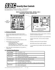
Installation - SDC Security Door Controls
Installation - SDC Security Door Controls
Installation - SDC Security Door Controls

Create successful ePaper yourself
Turn your PDF publications into a flip-book with our unique Google optimized e-Paper software.
801 Avenida Acaso, Camarillo, Ca. 93041 • (805) 494-0622 • Fax: (805) 494-8861<br />
www.sdcsecurity.com • E-mail: service@sdcsecurity.com<br />
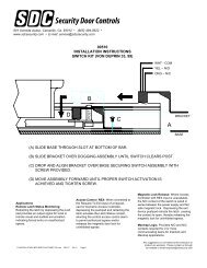
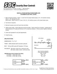
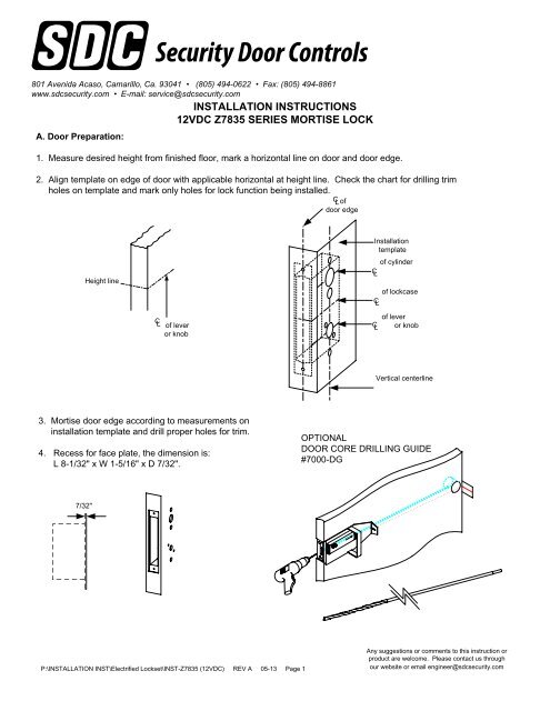
A. <strong>Door</strong> Preparation:<br />
INSTALLATION INSTRUCTIONS<br />
12VDC Z7835 SERIES MORTISE LOCK<br />
1. Measure desired height from finished floor, mark a horizontal line on door and door edge.<br />
2. Align template on edge of door with applicable horizontal at height line. Check the chart for drilling trim<br />
holes on template and mark only holes for lock function being installed.<br />
C L of<br />
door edge<br />
Height line<br />
C L of lever<br />
or knob<br />
<strong>Installation</strong><br />
template<br />
of cylinder<br />
C L<br />
C L<br />
C L<br />
of lockcase<br />
of lever<br />
or knob<br />
Vertical centerline<br />
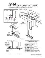
3. Mortise door edge according to measurements on<br />
installation template and drill proper holes for trim.<br />
4. Recess for face plate, the dimension is:<br />
L 8-1/32" x W 1-5/16" x D 7/32".<br />
OPTIONAL<br />
DOOR CORE DRILLING GUIDE<br />
#7000-DG<br />
7/32"<br />
P:\INSTALLATION INST\Electrified Lockset\INST-Z7835 (12VDC) REV A 05-13 Page 1<br />
Any suggestions or comments to this instruction or<br />
product are welcome. Please contact us through<br />
our website or email engineer@sdcsecurity.com
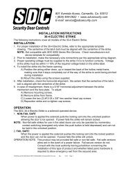
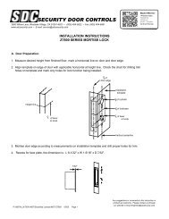
B. Strike <strong>Installation</strong>:<br />
1. Align strike template on jamb. Be sure to keep 3/8" distance between lock centerline and strike<br />
centerline. Recess 5/32" for flush fit of strike and dust box.<br />
2. Mortise jamb according to measurement of strike template. Then fit strike and dust box into frame<br />
and secure into place with supplied screws.<br />
Jamb C L<br />
4-7/8"<br />
3-17/32"<br />
1" Holes<br />
1-1/8" Deep<br />
Strike C<br />
3/8" L<br />
Lock C L<br />
3/8"<br />
C. Install Lockcase<br />
Instructions for changing latchbolt handing:<br />
1. Change latchbolt handing<br />
If the hand of the latchbolt doesn’t match the door hand, remove the fixing screw and pull the latchbolt out from<br />
lock case. Turn the latchbolt 180 ° to change the handling. Position latchbolt back, into case and fasten it.<br />
Remove screw<br />
Pull out and turn<br />
P:\INSTALLATION INST\Electrified Lockset\INST-Z7835 (12VDC) REV A 05-13 Page 2
C. Install Lockcase (Continued)<br />
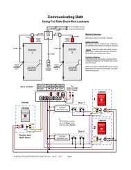
2. Connect wires as shown on the lock cover diagram.<br />
3. Insert lockcase into mortise cut-out and fasten screws to door.<br />
D. Install Spindles<br />
1. Insert spindle into outside hub of lock.<br />
2. Insert inside spindle and tighten screw into outside spindle.<br />
E. Install Lever trim<br />
1. Place the reversible spring cage onto the ferrules with arrow pointing in direction of lever rotation.<br />
2. Install outside trim with mounting posts through door and position lever onto the spindle.<br />
Reversible spring cage<br />
Ferrule<br />
Mounting post<br />
Screw post<br />
P:\INSTALLATION INST\Electrified Lockset\INST-Z7835 (12VDC) REV A 05-13 Page 3
E. Install Lever trim (Continued)<br />
3. Install inside spring cage onto the spindle with the arrow pointing in the direction of inside lever rotation.<br />
4. Install inside mounting plate onto spindle. Tighten with provided screw.<br />
5. Cap inside rose over mounting plate.<br />
6. Screw inside lever into position and tighten lever collar with spanner wrench.<br />
Spanner wrench<br />
F. Install Cylinder and Armor Face Plate<br />
1. Screw cylinder into threaded hole of lock case.<br />
2. Tighten the setting screw against cylinder(s) by turning clockwise as shown.<br />
3. Install face plate onto lock case front and fasten with supplied screws.<br />
USE THIS CAM.<br />
P:\INSTALLATION INST\Electrified Lockset\INST-Z7835 (12VDC) REV A 05-13 Page 4
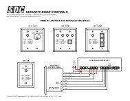
INSTALLATION WIRE DIAGRAM<br />
Model Z7835 Series 12VDC ONLY<br />
STANDARD WIRING<br />
(NO OPTIONS)<br />
+<br />
+<br />
-<br />
12VDC<br />
RED OUTSIDE<br />
BLK INSIDE<br />
NOT USED<br />
WHT<br />
4 PIN<br />
CONECTOR<br />
DPS<br />
REX<br />
LLS<br />
GREEN COM<br />
BLACK N/C<br />
WHITE N/O<br />
ORANGE COM<br />
BROWN N/C<br />
YELLOW N/O<br />
RED/YELLOW COM<br />
RED/BLACK SECURE<br />
RED/GREEN UNSECURE<br />
WIRING WITH OPTIONS<br />
SOLENOID<br />
VIOLET (+) OUTSIDE SOLENOID<br />
GREY (-) OUT/INSIDE SOLENOID<br />
PINK (+) INSIDE SOLENOID<br />
NOT<br />
USED<br />
P:\INSTALLATION INST\Electrified Lockset\INST-Z7835 (12VDC) REV A 05-13 Page 5
801 Avenida Acaso, Camarillo, Ca. 93041 • (805) 494-0622 • Fax: (805) 494-8861<br />
www.sdcsecurity.com • E-mail: service@sdcsecurity.com<br />
A. <strong>Door</strong> Preparation:<br />
INSTALLATION INSTRUCTIONS<br />
24VDC Z7835 SERIES MORTISE LOCK<br />
1. Measure desired height from finished floor, mark a horizontal line on door and door edge.<br />
2. Align template on edge of door with applicable horizontal at height line. Check the chart for drilling trim<br />
holes on template and mark only holes for lock function being installed.<br />
C L of<br />
door edge<br />
Height line<br />
C L of lever<br />
or knob<br />
<strong>Installation</strong><br />
template<br />
of cylinder<br />
C L<br />
C L<br />
C L<br />
of lockcase<br />
of lever<br />
or knob<br />
Vertical centerline<br />
3. Mortise door edge according to measurements on<br />
installation template and drill proper holes for trim.<br />
4. Recess for face plate, the dimension is:<br />
L 8-1/32" x W 1-5/16" x D 7/32".<br />
OPTIONAL<br />
DOOR CORE DRILLING GUIDE<br />
#7000-DG<br />
7/32"<br />
P:\INSTALLATION INST\Electrified Lockset\INST-Z7835 (24VDC) REV D 05-13 Page 1<br />
Any suggestions or comments to this instruction or<br />
product are welcome. Please contact us through<br />
our website or email engineer@sdcsecurity.com
B. Strike <strong>Installation</strong>:<br />
1. Align strike template on jamb. Be sure to keep 3/8" distance between lock centerline and strike<br />
centerline. Recess 5/32" for flush fit of strike and dust box.<br />
2. Mortise jamb according to measurement of strike template. Then fit strike and dust box into frame<br />
and secure into place with supplied screws.<br />
Jamb C L<br />
4-7/8"<br />
3-17/32"<br />
1" Holes<br />
1-1/8" Deep<br />
Strike C<br />
3/8" L<br />
Lock C L<br />
3/8"<br />
C. Install Lockcase<br />
Instructions for changing latchbolt handing:<br />
1. Change latchbolt handing<br />
If the hand of the latchbolt doesn’t match the door hand, remove the fixing screw and pull the latchbolt out from<br />
lock case. Turn the latchbolt 180 ° to change the handling. Position latchbolt back, into case and fasten it.<br />
Remove screw<br />
Pull out and turn<br />
P:\INSTALLATION INST\Electrified Lockset\INST-Z7835 (24VDC) REV D 05-13 Page 2
C. Install Lockcase (Continued)<br />
2. Connect wires as shown on the lock cover diagram.<br />
3. Insert lockcase into mortise cut-out and fasten screws to door.<br />
D. Install Spindles<br />
1. Insert spindle into outside hub of lock.<br />
2. Insert inside spindle and tighten screw into outside spindle.<br />
E. Install Lever trim<br />
1. Place the reversible spring cage onto the ferrules with arrow pointing in direction of lever rotation.<br />
2. Install outside trim with mounting posts through door and position lever onto the spindle.<br />
Reversible spring cage<br />
Ferrule<br />
Mounting post<br />
Screw post<br />
P:\INSTALLATION INST\Electrified Lockset\INST-Z7835 (24VDC) REV D 05-13 Page 3
E. Install Lever trim (Continued)<br />
3. Install inside spring cage onto the spindle with the arrow pointing in the direction of inside lever rotation.<br />
4. Install inside mounting plate onto spindle. Tighten with provided screw.<br />
5. Cap inside rose over mounting plate.<br />
6. Screw inside lever into position and tighten lever collar with spanner wrench.<br />
Spanner wrench<br />
F. Install Cylinder and Armor Face Plate<br />
1. Screw cylinder into threaded hole of lock case.<br />
2. Tighten the setting screw against cylinder(s) by turning clockwise as shown.<br />
3. Install face plate onto lock case front and fasten with supplied screws.<br />
USE THIS CAM.<br />
P:\INSTALLATION INST\Electrified Lockset\INST-Z7835 (24VDC) REV D 05-13 Page 4
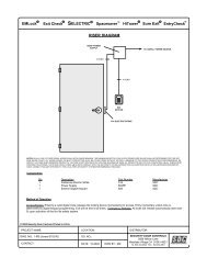
INSTALLATION WIRE DIAGRAM<br />
Model Z7835 Series 24VDC ONLY<br />
STANDARD WIRING<br />
(NO OPTIONS)<br />
+<br />
+<br />
-<br />
24VDC<br />
RED OUTSIDE<br />
NOT USED<br />
BLK INSIDE<br />
WHT<br />
4 PIN<br />
CONECTOR<br />
DPS<br />
REX<br />
LLS<br />
GREEN COM<br />
BLACK N/C<br />
WHITE N/O<br />
ORANGE COM<br />
BROWN N/C<br />
YELLOW N/O<br />
RED/YELLOW COM<br />
RED/BLACK SECURE<br />
RED/GREEN UNSECURE<br />
WIRING WITH OPTIONS<br />
SOLENOID<br />
VIOLET (+) OUTSIDE SOLENOID<br />
GREY (-) OUT/INSIDE SOLENOID<br />
PINK (+) INSIDE SOLENOID<br />
NOT<br />
USED<br />
P:\INSTALLATION INST\Electrified Lockset\INST-Z7835 (24VDC) REV D 05-13 Page 5