Reporter No 60, May 2009, English (PDF 2,58 MB) - Leica ...
Reporter No 60, May 2009, English (PDF 2,58 MB) - Leica ...
Reporter No 60, May 2009, English (PDF 2,58 MB) - Leica ...

Create successful ePaper yourself
Turn your PDF publications into a flip-book with our unique Google optimized e-Paper software.
<strong>60</strong><br />
The Global Magazine of <strong>Leica</strong> Geosystems
Editorial<br />
Dear Readers,<br />
A new edition of the “<strong>Reporter</strong>” lies on my desk,<br />
ready for printing. At such moments, the thought<br />
crosses my mind how exciting the business we all<br />
work in is. In close cooperation with our customers,<br />
the editorial team manages to present the whole<br />
range of measurement technologies – geomatics,<br />
engineering, construction, machine control, geographic<br />
information systems, and high definition<br />
scanning – by describing fascinating projects. These<br />
projects, realized by our customers, are very diverse:<br />
for example the Arabian Canal in Dubai’s desert, the<br />
Gotthard base tunnel in Switzerland, an American oil<br />
CONTENTS<br />
03<br />
06<br />
08<br />
10<br />
12<br />
14<br />
18<br />
22<br />
23<br />
23<br />
57 km long and<br />
in the right Place<br />
The City Walls of Dubrovnik<br />
Project Savings at Deer Park<br />
Arabian Canal:<br />
A Miracle in the Making<br />
Laser Land Levelling<br />
Refined Dimensions<br />
A new Level of Precision<br />
<strong>Leica</strong> TS30: Pride in Accuracy<br />
NRS TruStory:<br />
First Prize goes to Latvia<br />
<strong>Leica</strong> Geosystems Technologies:<br />
«Singapore Quality Class»<br />
refinery, or the capturing and processing of digital<br />
aerial images in the UK.<br />
Infrastructure projects are an important factor in<br />
helping to ease the economic crisis that dominates<br />
the news as well as our everyday conversations at<br />
the moment. This is also demonstrated through the<br />
economic stimulus programmes launched by governments<br />
all around the world. Sustainability, stability,<br />
and reliability are becoming increasingly important.<br />
At <strong>Leica</strong> Geosystems, we combine these values with a<br />
deep understanding of users’ needs – accuracy, productivity,<br />
and efficiency. Transferring these values<br />
and this knowledge into products and solutions, we<br />
enable our customers to stay ahead of their competitors.<br />
Thus, we not only contribute to their economic<br />
success, but also ensure that our “<strong>Reporter</strong>”-Team<br />
will have exciting projects to present in the future.<br />
Enjoy reading!<br />
Ola Rollén<br />
CEO Hexagon and <strong>Leica</strong> Geosystems<br />
Imprint<br />
<strong>Reporter</strong>: Customer Magazine of <strong>Leica</strong> Geosystems<br />
Published by: <strong>Leica</strong> Geosystems AG, CH-9435 Heerbrugg<br />
Editorial Office: <strong>Leica</strong> Geosystems AG,<br />
9435 Heerbrugg, Switzerland, Phone +41 71 727 34 08,<br />
reporter@leica-geosystems.com<br />
Contents responsible: Alessandra Doëll<br />
(Director Communications)<br />
Editor: Agnes Zeiner<br />
Publication details: The <strong>Reporter</strong> is published in <strong>English</strong>,<br />
German, French, and Spanish, twice a year.<br />
Reprints and translations, including excerpts, are subject to<br />
the editor’s prior permission in writing.<br />
© <strong>Leica</strong> Geosystems AG, Heerbrugg (Switzerland),<br />
<strong>May</strong> <strong>2009</strong>. Printed in Switzerland<br />
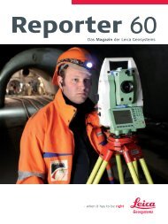
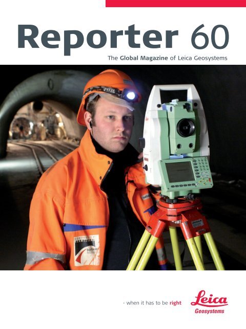
Cover: BSF Swissphoto AG: Employee Reto Bardill<br />
surveying in the Gotthard base tunnel<br />
2 | <strong>Reporter</strong>
57 km long and<br />
in the right Place<br />
by Agnes Zeiner, Pictures: BSF Swissphoto AG<br />
With the modernization of its railway infrastructure,<br />
Switzerland seeks to connect to the<br />
European high-speed train network and achieve<br />
a reduction in the amount of the transit traffic<br />
on its roads. One of the key projects is the “Alp-<br />
Transit Gotthard”, at the heart of which is the<br />
Gotthard Base Tunnel: A 57-km-long twin-tube<br />
railway tunnel and the longest tunnel in Europe.<br />
A challenge to the surveyors – under and on the<br />
mountain.<br />
Switzerland lies at the centre of Europe and the Alps.<br />
This compact country of blooming alpine pastures<br />
and the classic children's story of Heidi, is the same<br />
country that has a major share of European traffic<br />
rolling through it north to south – and back again.<br />
Traffic flows have increased continuously over the<br />
decades, as more and more people and goods cross<br />
the Alps in both directions. One of the most important<br />
transit routes in Europe passes over the 2’108 m<br />
high St. Gotthard Pass.<br />
Modern low-level rail link<br />
with speeds of up to 250 km/h<br />
The Gotthard Rail Tunnel was built more than 125<br />
years ago. Otto Gelpke and Carl Koppe, two surveyors<br />
working independently of one another, each<br />
created a triangulation network, which – checked<br />
by comparison of the two meshes – was to form<br />
the basis for all the later surveys. In 1880 when the<br />
breakthrough of the 15 km long Gotthard Rail Tunnel<br />
took place, the deviation of the two headings was<br />
only 30 cm – an incredible success for the surveyors<br />
involved.<br />
>><br />
The Global Magazine of <strong>Leica</strong> Geosystems | 3
Gotthard Base Tunnel<br />
Length: 57 km<br />
Scheduled completion: End of 2017<br />
Construction costs (2008):<br />
6.43 billion euro (8.62 billion US$)<br />
Construction costs (2008) including Ceneri<br />
Base Tunnel: 7.76 billion euro (10.41 billion US$)<br />
Surveying:<br />
Consortium VI-GBT c/o Grünenfelder und Partner AG<br />
and ARGE LOS349 c/o BSF Swissphoto AG,<br />
www.bsf-swissphoto.ch<br />
Instruments used for tunnel surveying:<br />
Precision total station <strong>Leica</strong> TCA2003<br />
Digital level <strong>Leica</strong> DNA03<br />
Nadirlot NL<br />
Instruments used for monitoring :<br />
Precision total station <strong>Leica</strong> TCA2003<br />
Monitoring software <strong>Leica</strong> GeoMoS<br />
<strong>Leica</strong> GPS System 500<br />
Monitoring the Nalps dam wall<br />
This would have been way outside the accuracy of<br />
10 cm horizontally and 5 cm vertically required of the<br />
engineers working for the surveying consortium VI-<br />
GBT today, because the new Gotthard Base Tunnel<br />
is designed for a modern low-level, high-speed railway.<br />
The highest point on the route is only 550 m<br />
above sea level and the maximum gradient is limited<br />
to 0.8 percent. This means that from the end<br />
of 2017 (scheduled date), high-speed trains with<br />
people, goods, and vehicles on board will be carried<br />
safely through the Alps at speeds of up to 250 km/h.<br />
Perfect alignment of the track is essential for this to<br />
happen.<br />
The hole in the right place<br />
Ensuring that the alignment complies with these<br />
requirements is the task of Ivo Schätti and his team<br />
from Grünenfelder & Partner AG, the lead engineering<br />
consultancy in the surveying consortium. As the<br />
client's surveying engineers, they are responsible for<br />
maintaining the correct position, height, and direction<br />
as the mega-tunnel heading advances. “You<br />
could say we have to make sure the hole is in the<br />
right place,” grins Schätti during our visit to his office<br />
in Domat-Ems, a small town near the Gotthard section<br />
of the works. A map on the wall showing the<br />
whole project gives rise to the suspicion that it might<br />
be somewhat more difficult than that. “The special<br />
aspects of this project naturally include its length,<br />
the five entry points out of which we work, and of<br />
course the required accuracy,” he adds.<br />
Great effort for control surveys<br />
The mega-tunnel is being built from five places at<br />
once – the two portals at Erstfeld (north) and Bodio<br />
(south), and intermediate headings at Amsteg, Sedrun,<br />
and Faido. The basic primary network was created<br />
in 1995 and was completely resurveyed ten years<br />
later. “In 1995 the use of GPS was still relatively new,<br />
but our measurements confirmed that the points<br />
were stable,” declared Schätti.<br />
One of the principal tasks of Grünenfelder & Partner<br />
AG at the moment is tunnel control. As the client's<br />
surveyors, the team can take more time for its measurements,<br />
but also work more intensely, using special<br />
instruments such as a gyrotheodolite and enjoying<br />
better working conditions than the contractor's<br />
survey teams, who continuously monitor and control<br />
the heading. Their measurements are usually taken<br />
when the site is shut down. “This entails coming into<br />
work over Christmas and on other public holidays,”<br />
says Schätti.<br />
The checks are necessary as errors can creep in<br />
through many factors. One source of errors is temperature<br />
fluctuations: ventilation equipment distributes<br />
the relatively high temperatures uniformly<br />
4 | <strong>Reporter</strong>
under the mountain specifically for the surveying<br />
operations and the survey concept was designed to<br />
suit these conditions. “When you are underground<br />
you do not know how gravity is behaving in response<br />
to different rock densities – these errors would be<br />
transferred immediately into our measurements.<br />
Therefore we refer back to survey models based<br />
on measurements we have taken on the surface,”<br />
explains Ivo Schätti.<br />
Dam wall monitoring on the surface<br />
While the tunnel boring machines are continuously<br />
eating their way through the base of the Gotthard<br />
massif, other measurements are being taken on<br />
the surface. Some parts of the tunnel pass directly<br />
under three water storage reservoirs, and although<br />
the tunnel lies very far underground, the effects on<br />
the surface should not be underestimated. “A tunnel<br />
affects the normal flows and pressures of ground<br />
water. The pressure loss due to the removal of the<br />
water in the rock could cause the mountain literally to<br />
cave in,” explains Ivo Schätti. A change of pressure like<br />
this could have disastrous consequences for the dam<br />
walls of the three reservoirs at Curnera, Nalps, and<br />
Santa Maria in the Upper Rhine Valley – and the tunnel<br />
driving would have to be stopped immediately.<br />
monitoring the valley walls near the dam walls and<br />
the area in front of them. Measuring points were<br />
fixed directly on the rock or were set on up to 3-<br />
metre-high concrete pillars which the team constructed<br />
themselves. <strong>No</strong> easy task, given that all the<br />
materials had to be flown in by helicopter and the<br />
prisms fixed on to vertical rock faces. Highly precise<br />
<strong>Leica</strong> TCA2003 total stations, protected against<br />
the weather in small enclosures and controlled using<br />
<strong>Leica</strong> GeoMoS, measure the movements of the prisms<br />
and transmit the data to monitoring software developed<br />
in-house. “The instruments have been operating<br />
since 2000 and continue to work perfectly,” he<br />
adds on behalf of a satisfied BSF Swissphoto. Spot<br />
level surveys were carried out at particularly critical<br />
areas along the route using a <strong>Leica</strong> GPS System 500<br />
to determine the settlement of individual points.<br />
The long, hard winters in the Swiss mountains make<br />
the team's job even more difficult: “In places the<br />
snow depths are huge, some points in avalanche<br />
areas are off limits for the whole of the winter, and<br />
often ice forms on the prisms and can remain there<br />
all day. In spite of all this we have been able to reach<br />
90 percent of our points, even in the winter,” concludes<br />
Ivo Schätti.<br />
For this reason BSF Swissphoto AG, the lead surveying<br />
consultant of the ARGE Los349 consortium, is<br />
The Global Magazine of <strong>Leica</strong> Geosystems | 5
The City Walls<br />
of Dubrovnik<br />
by Miljenko Žabcic; Picture: Gerald Loacker<br />
Geographica d.o.o. recently completed a major<br />
project which included scanning and comprehensive<br />
documentation of the almost 2 km long<br />
city walls of Dubrovnik in the very south of Croatia<br />
for the “Society of Friends of Dubrovnik's<br />
Cultural Heritage”, a group of engaged citizens.<br />
The medieval city, nicknamed “the Pearl of the<br />
Adriatic”, is on the UNESCO list of World Heritage<br />
Sites. Purpose of the four year project was<br />
to fully document the current state of the city<br />
walls and fortresses for future improvements<br />
and in order to preserve their current state for<br />
upcoming generations.<br />
The “Society of Friends of Dubrovnik's Cultural<br />
Heritage” (Društvo prijatelja dubrovacke starine)<br />
approached Geographica d.o.o. in 2004, as<br />
Dubrovnik’s city walls hadn't ever been completely<br />
documented before. 3D laser scanning was selected<br />
as the best method. The documentation included<br />
scanning, modeling, and drawing and will be used<br />
for multiple purposes such as everyday maintenance,<br />
legal requirements, interior design for functionality<br />
improvements, cost estimate calculations for various<br />
work, study of the object in terms of its origin, and<br />
building stages.<br />
The town fortifications, ramparts, and towers outside<br />
the walls were built, reinforced, and reconstructed<br />
in the period from the 12 th to the second<br />
half of the 17 th century. A number of engineers were<br />
involved in these works – well known names such as<br />
Nicifor Ranjina in 1319, Michelozzo di Bartholomeo in<br />
1461–1464, Juraj Dalmatinac or George the Dalmatian<br />
in 1465–1466, Paskoje Milicevic in 1466–1516,<br />
and Antonio Ferramolino in 1538.<br />
The main wall is 1’940 m long (following the ring-corridor),<br />
4–6 m wide on the mainland side and between<br />
1.5 and 5 m wide on the sea side. It is up to 25 m high<br />
in parts. The wall was reinforced by three circular and<br />
14 quadrangular towers, five bastions (bulwarks),<br />
two angular fortifications, and a large fortress called<br />
Sveti Ivan (St. John). Among the towers, the most<br />
monumental is the circular tower of Minceta, on the<br />
north-western corner of the ramparts. The reinforcement,<br />
along the main wall on the mainland side,<br />
includes one larger and nine smaller semicircular bastions,<br />
and the casemate fortress Bokar, the oldest<br />
preserved fortress of its kind in Europe.<br />
Very dense scan data<br />
Since one of the products to be achieved with the<br />
scan data were plane drawings of the current state<br />
of the walls, including drawings of the wall’s struc-<br />
6 | <strong>Reporter</strong>
ture, scans had to be very dense. Therefore all the<br />
walls ware scanned with a resolution of under 1 cm,<br />
usually around 5–8 mm, depending of the shape of<br />
the stones. Only the interiors of the fortresses were<br />
scanned with a resolution of 2.5 cm. The scan data is<br />
a very important part of the final product because it<br />
will be used in the future for precise measurements<br />
in the process of preservation.<br />
3D model as simplified representation<br />
A 3D model was created as a simplified representation<br />
of the walls and fortresses but it contained all<br />
main construction elements of the walls. It is used<br />
for general planning in various projects, fast overview<br />
of parts of interest, calculations of quantity and<br />
expenses in preservation works and presentations.<br />
The model was created in two steps. The first step<br />
was edge extraction, done with <strong>Leica</strong> Cyclone Software<br />
by converting the edges of scan data into lines<br />
and polylines. The second step was the generation<br />
of surfaces from the extracted edges. Surfaces were<br />
generated in a CAD environment to ensure the whole<br />
model is suitable for a wide range of applications<br />
and users.<br />
Plane drawings as documentation<br />
of the current state<br />
Generating the plane drawings was the most<br />
demanding and time-consuming part of the project.<br />
According to Croatian laws of preservation of cultural<br />
heritage this documentation has to be prepared for<br />
plot with a scale factor of 1 : 50 and must include<br />
ground views, horizontal, and vertical sections and<br />
facade (elevation) views with stone structure. Every<br />
drawing has to be dimensioned with plane and height<br />
dimensions.<br />
Drawings were created in a CAD environment using<br />
<strong>Leica</strong> CloudWorks for AutoCAD. These drawings are<br />
very detailed and contain all the segments of the<br />
walls including drawings of every individual stone.<br />
The number of required drawings was not defined at<br />
the project beginning. There have to be enough to<br />
represent every part of the walls and every segment<br />
of its construction. In case of disaster it must be possible<br />
to completely reconstruct the walls according<br />
to this documentation. Such drawings are also used<br />
for detailed planning in preservation and restoration,<br />
studying the walls’ history and phases of building,<br />
everyday preservation works in the field, and various<br />
other tasks.<br />
About the author:<br />
Miljenko Žabcic is a surveying engineer and director<br />
of Geographica d.o.o. in Split, Croatia. Geographica<br />
d.o.o., founded in 1999, employs 12 experts covering<br />
the fields of geodesy, architecture, construction, and<br />
archaeology. The company was the first in Croatia to<br />
start using 3D laser scanning technology in 2003.<br />
City Walls of Dubrovnik<br />
Total perimeter (including both sides<br />
of the walls): 4’300 m<br />
Total scanned area: 120’000 m²<br />
Scanning time: 240 days (1 scanner, 2 operators)<br />
Products: <strong>Leica</strong> HDS2500, <strong>Leica</strong> ScanStation<br />
Total project time: 4 years with two persons<br />
in the field and three persons in the office<br />
The Global Magazine of <strong>Leica</strong> Geosystems | 7
Project Savings<br />
at Deer Park<br />
by Stefana Vella<br />
One of Australia’s leading construction companies,<br />
Leighton Contractors, is realizing the<br />
benefits of using <strong>Leica</strong> GradeSmart and <strong>Leica</strong><br />
DigSmart machine control technology during<br />
construction of Melbourne’s $331 million,<br />
9.3 km Deer Park bypass. <strong>Leica</strong> Geosystems distributors<br />
CR Kennedy fitted several graders and<br />
excavators with the latest GNSS 3D technology<br />
to deliver higher productivity, machine utilization,<br />
and performance.<br />
on investment was straightforward, Mr. Wall said:<br />
“The grader systems have basically cut out the need<br />
for two or three blokes with stringlines and pegs for<br />
each machine. And with the two excavator systems<br />
we have also been able to cut a man out because we<br />
don’t need a spotter measuring with the excavators.<br />
The systems are cheap to buy when compared to<br />
what you are saving. When you add up nine wages if<br />
you were using surveying crews you are miles ahead<br />
and over a two-year project like this that adds up to<br />
substantial wage costs. You also don’t have to water<br />
or feed them or get them out of the weather.”<br />
The Deer Park bypass is the largest design and construction<br />
contract awarded by VicRoads and features<br />
four lanes and four major interchanges over its 9.3 km<br />
length. Scheduled to open in late <strong>2009</strong>, the bypass<br />
will eliminate 20 intersections and is expected to<br />
reduce journeys by up to 15 minutes.<br />
Leighton Construction Manager Ray Wall chose to<br />
equip three graders (two John Deere 872 and a Caterpillar<br />
140H) with <strong>Leica</strong> GradeSmart 3D technology<br />
and to fit two subcontractor excavators with <strong>Leica</strong><br />
DigSmart 3D guidance systems. Calculating the return<br />
Compatibility with surveying equipment<br />
Deer Park bypass senior surveyor, Greg Bennett of<br />
GW Bennett & Associates said <strong>Leica</strong> Geosystems’<br />
compatibility with surveyor’s equipment was a major<br />
feature. “We load the designs straight from our <strong>Leica</strong><br />
LISCAD software already in the format required by<br />
the graders. With the <strong>Leica</strong> Geosystems’ system we<br />
can also load much more information onto the data<br />
card than any other system available and we can do<br />
it quicker because there are no compatibility problems.<br />
We can load 16 <strong>MB</strong> of data on one data card,<br />
but we generally break the project into two design<br />
8 | <strong>Reporter</strong>
models of about 8 <strong>MB</strong> each. Compare that to some<br />
other systems that will only take 1 <strong>MB</strong> total – it is a<br />
massive advantage,” he said.<br />
One-man operation<br />
Fitting <strong>Leica</strong> DigSmart 3D technology to two contractor’s<br />
excavators has also delivered timesavings for<br />
Leighton Contractors. “With excavators you’d generally<br />
have to peg trenches up to three times as they<br />
got closer to the design, now with <strong>Leica</strong> Geosystems’<br />
technology we start at ground level and go through<br />
in a complete cut – the operator does everything<br />
according to the instructions,” Mr. Wall said. “It is<br />
basically stake-less and with GNSS is accurate to<br />
± 30 mm so when we are pulling up batters it is probably<br />
20 percent quicker and you don’t have to wait<br />
for anyone to grade check – it becomes a one-man<br />
operation.”<br />
Ray Wall added: “This gives us great flexibility with<br />
the graders because we can move them anywhere<br />
on the project – with other systems we are limited<br />
until we load new designs if a grader needs to move.”<br />
Set in automatic mode, the <strong>Leica</strong> GradeSmart 3D system<br />
precisely controls the blade to the design model<br />
loaded, moving it to the required elevation, angle,<br />
and side shift in real time – eliminating operator<br />
guesswork, multipassing, and the need for re-work.<br />
“Wouldn’t do it any other way”<br />
<strong>Leica</strong> DigSmart monitors the precise position of the<br />
digging bucket with the data appearing via an onboard<br />
monitor in real time allowing the operator to<br />
excavate, trench, or batter confidently. “We can have<br />
the GNSS machine cut slots in batters every 20 m<br />
and then put another excavator in there to work off<br />
those slots,” Mr. Wall said. “The accuracy we achieve<br />
using DigSmart when digging drains and other earthworks<br />
is a lot better than having an operator trying<br />
to measure off pegs. This is the first job where we’ve<br />
had a lot to do with the stake-less systems – I’ve<br />
seen it at EastLink [compare <strong>Reporter</strong> 57] and was<br />
impressed with it and thought we would give it a go<br />
here. <strong>No</strong>w I wouldn’t do it any other way.”<br />
About the author:<br />
Stefana Vella is Business Development Consultant and<br />
Marketing Manager for Machine Control at C.R. Kennedy<br />
& Company Pty. Ltd., <strong>Leica</strong> Geosystems Dealer<br />
in Australia.<br />
The Global Magazine of <strong>Leica</strong> Geosystems | 9
Arabian Canal:<br />
A Miracle in<br />
the Making<br />
by Agnes Zeiner<br />
“Like our CEO, Saeed Ahmed Saeed, one must<br />
be visionary,” insists Dr. Nedal Al-Hanbali, Head<br />
of Corporate Geomatics Information Systems at<br />
Limitless LLC. Visionary is the way to describe<br />
the Arabian Canal, a project on which the surveyor<br />
will work for the next 15 years. In the<br />
Dubai desert, Limitless is building a 75 km long<br />
canal and waterside city where up to two million<br />
people will live and work.<br />
Nedal Al-Hanbali’s life can be defined as dedicated<br />
to establishing and building a new standard and<br />
caliber of Geomatics/GIS in the real estate industry<br />
using state-of-the-art technologies. One of his most<br />
important projects is the Arabian Canal. “At Limitless<br />
we have visionary objectives that do not remain<br />
dreams, but are actually realized. The consequences<br />
are projects as unique and innovative as the Arabian<br />
Canal. This visionary approach is the reason I joined<br />
Limitless,” explains the Geomatics/Surveying expert,<br />
former professor at the Al-Balqa’ University in Jordan<br />
and researcher at the University of Calgary/Canada.<br />
Modern city in the Dubai desert<br />
This fascinating project involves construction of a<br />
75 km long canal, in the shape of a horseshoe, flowing<br />
inland from Palm Jumeirah harbor to the west to<br />
the new Dubai World Central International Airport,<br />
and east to the harbor area again. It will be approximately<br />
150 m wide and 6 m deep.<br />
10 | <strong>Reporter</strong>
On its banks will be hills and valleys – a new topography<br />
for Dubai – and a modern, sustainable city.<br />
Supplied with water from the Gulf, Arabian Canal<br />
will have marinas, promenades, beaches, and public<br />
transport on the canal. Construction costs for the<br />
waterway – the most complex civil engineering project<br />
ever undertaken in the Middle East – are estimated<br />
at US$11 billion.<br />
For a project of this magnitude it is crucial to use<br />
resources as economically as possible. “The project<br />
involves moving large amounts of earth each day,<br />
which requires a highly efficient system,” explains<br />
Dr. Nedal. “The basis for the system is a model of<br />
the terrain that is constantly kept up to date with<br />
the aid of a complex interaction between total stations,<br />
GPS/GNSS, HDS scanners, airborne digital sensor<br />
cameras with LIDAR, reference stations, and to<br />
some extent custom software.”<br />
Continuous support<br />
Several <strong>Leica</strong> Geosystems instruments for static and<br />
dynamic measurements are used in this process. A<br />
high definition scanner, <strong>Leica</strong> ScanStation 2, provides<br />
point clouds of the terrain, while <strong>Leica</strong> SmartPoles<br />
are used for the surveying. A dedicated GNSS reference<br />
station network with five stations and <strong>Leica</strong><br />
GNSS Spider software provide the necessary RTK<br />
correction data for the entire area. Soon a further<br />
reference station will be added.<br />
Before appointing <strong>Leica</strong> Geosystems as a supplier, a<br />
number of possible systems were put through their<br />
paces, explains Nedal Al-Hanbali. “We organized<br />
a ‘competition’ between the various providers to<br />
obtain the best possible instruments for our requirements.<br />
Important factors included speed, efficiency,<br />
accuracy, the integration of software and workflows,<br />
and also the customer support and people behind<br />
these products. During this process all companies<br />
offered their equipment for several days of testing in<br />
the Arabian Canal pilot excavation. The regional sales<br />
partner for <strong>Leica</strong> Geosystems, Geco, was very cooperative,<br />
offering their scanner for three consecutive<br />
tests to explore all possible scanning and processing<br />
possibilities. As a result we could check on-site that<br />
the instruments – and service – met our requirements.<br />
Geco now also provides us with continuous<br />
support during the construction phase.”<br />
Limitless LLC<br />
Global Real Estate Developer<br />
Business unit of Dubai World,<br />
one of Dubai's leading business groups<br />
Set up in July 2005<br />
CEO: Saeed Ahmed Saeed<br />
Vision: “To enhance and enrich lives through the<br />
delivery of distinctive, sustainable developments.”<br />
Geco – General<br />
Enterprises Company<br />
<strong>Leica</strong> Geosystems’ Partner<br />
in the United Arab Emirates for 32 years<br />
Distribution, training, and service<br />
30 employees<br />
Projects:<br />
Al Garhoud Bridge, Dubai<br />
Reference station network Abu Dhabi<br />
Burj Dubai [see <strong>Reporter</strong> 56]<br />
Abu Dhabi Airport<br />
The Global Magazine of <strong>Leica</strong> Geosystems | 11
Laser Land Levelling<br />
by Raymond Chia<br />
The economical benefits of perfectly levelled<br />
fields are enormous, especially in India. For<br />
instance, a levelled field results in substantial<br />
watersavings and an increase in yield and product<br />
quality. Rotating lasers have become essential<br />
tools for agricultural applications. They make<br />
faster work of many jobs, while eliminating costly<br />
errors for precise levelling. Once considered “nice<br />
to have,” today they are a competitive “must have”<br />
to get the job done efficiently and precisely.<br />
Uneven soil surface has a major impact on the germination,<br />
stand, and yield of crops due to inhomogeneous<br />
water distribution and soil moisture. Therefore,<br />
land levelling is a precursor to good agronomic,<br />
soil, and crop management practices. Furthermore,<br />
resource conservation technologies perform better<br />
on well-levelled and laid-out fields.<br />
Benefits of land levelling<br />
Effective land levelling optimises water-use, improves<br />
crop establishment, reduces the irrigation time and<br />
the effort required to manage the crop. It reduces<br />
the work in crop establishment and crop management,<br />
and increases the yield and product quality.<br />
Research has shown an increase in rice yield of up to<br />
24 percent due to good field levelling. A large part of<br />
this increase is realized due to improved weed control.<br />
Therefore, with the improved water coverage,<br />
resulting from proper levelling, the weeds can be<br />
reduced by up to 40 percent. In addition, land levelling<br />
frees up land for cultivation, resulting in larger<br />
fields and larger farming areas, which improves the<br />
operational efficiency. Furthermore, levelling reduces<br />
the time needed for planting and transplanting.<br />
It even gives a greater opportunity to use the much<br />
faster, direct seeding process.<br />
Efficiency of water use<br />
The average difference in height between the highest<br />
and lowest portions of rice fields in Asia is 1<strong>60</strong> mm.<br />
This means that in an unlevelled field an extra 80 mm<br />
to 100 mm of water must be stored in the field to<br />
give complete water coverage. This is nearly an extra<br />
10 percent of the total water requirement to grow<br />
the crop. Land levelling effectively terraces fields,<br />
allowing water in the higher fields to be used in the<br />
lower fields for land preparation, plant establishment,<br />
and irrigation.<br />
Economics of land levelling<br />
The initial cost of land levelling using contractor sand<br />
machinery is high. This cost varies with the volume<br />
of soil to be moved and the soil type. However, using<br />
12 | <strong>Reporter</strong>
Principle of Laser Land Levelling<br />
<strong>Leica</strong> Rugby 100LR<br />
transmits the laser beam<br />
<strong>Leica</strong> MLS700 Sensor<br />
detects the laser beam<br />
<strong>Leica</strong> MCP700 Control Panel helps<br />
control the level of the machine<br />
Levelled land<br />
Land to be levelled<br />
more sophisticated equipment increases the area<br />
that can be levelled each day and several examples<br />
show that the initial costs are paid back within 1 or 2<br />
years due to the improved yield.<br />
Farmers recognize this and therefore devote considerable<br />
attention and resources to levelling their<br />
fields properly. However, traditional methods of levelling<br />
land are not only more cumbersome and timeconsuming,<br />
but more expensive as well. For instance,<br />
rice farmers level their fields very often under ponded<br />
water conditions. Others dry level their fields<br />
and check the level by ponding water. With these<br />
methods a considerable amount of water is wasted.<br />
Laser land levelling<br />
– the cost-effective solution<br />
Laser levelling systems are commonly used in agricultural<br />
applications in Australia, Japan, and the United<br />
States. Increasingly, laser-guided systems are being<br />
used in less developed country as well. The advantages<br />
are obvious:<br />
<strong>No</strong> waste of water to check the field level<br />
Reduced operating time<br />
Increased productivity<br />
Precisely levelled and smooth soil surface<br />
Before the levelling process can start, the fields must<br />
be to be plowed and a topographic survey undertaken,<br />
in most situations. Depending on the amount<br />
of soil that must be cut, it may be necessary to plow<br />
during and after the levelling operation, as well.<br />
MLS700 Laser Sensor and the <strong>Leica</strong> MCP700 Control<br />
Panel. The <strong>Leica</strong> Rugby 100LR is mounted on a tripod<br />
and placed in a central point of the field. This allows<br />
the laser beam to sweep unobstructed above the<br />
tractor. As the <strong>Leica</strong> Rugby 100LR has an operating<br />
range of 1’500 m in diameter, several tractors can<br />
work with the “plane of light above the field” coming<br />
from one device. The laser beam of the <strong>Leica</strong> Rugby<br />
100LR is detected by the <strong>Leica</strong> MLS700 Laser Sensor,<br />
which is mounted on the mast attached to the drag<br />
bucket. It transmits the signals to the <strong>Leica</strong> MCP700<br />
Control Panel, which controls the level of the machine<br />
and operates the hydraulic valves. With the hydraulic<br />
valves the levelling bucket can be raised and lowered.<br />
The desired rate at which the bucket has to be raised<br />
and lowered depends on the operating speed. The<br />
faster the ground speed, the faster the bucket will<br />
need to be adjusted.<br />
Once a field has been levelled, plowing techniques<br />
must be changed to keep it level. Farmers are encouraged<br />
to plow from the center of the field out rather<br />
than continuing to use the traditional technique of<br />
plowing from the outside of the field into the centre.<br />
If appropriate plowing techniques are used, re-levelling<br />
the whole field should not be necessary for at<br />
least eight to ten years.<br />
About the author:<br />
Raymond Chia works as regional marketing manager<br />
in Asia Pacific for the <strong>Leica</strong> Geosystems Precision<br />
Tools Division.<br />
An optimal combination of instruments for laser land<br />
levelling exists with the <strong>Leica</strong> Rugby 100LR, the <strong>Leica</strong><br />
The Global Magazine of <strong>Leica</strong> Geosystems | 13
Refined<br />
Dimensions<br />
by Seth Goucher and Brayden L. Sheive<br />
Today's modern oil refinery is a huge, efficient<br />
industrial facility that takes crude petroleum<br />
pumped from deep within the earth and turns<br />
it into useful products such as gasoline, aviation<br />
fuel, lubricating oil, home heating oil, and<br />
more. Motiva Enterprises LLC, a joint-venture<br />
owned by affiliates of Shell and Saudi Aramco,<br />
is building an epic expansion at its refinery in<br />
Port Arthur, Texas. This project is vital to providing<br />
additional transportation fuels for the<br />
American consumer.<br />
When completed in 2010, the Motiva Port Arthur<br />
Refinery Expansion Project will create a 325’000<br />
barrel-per-day (b/d) capacity expansion at the Port<br />
Arthur refinery, increasing its crude oil throughput<br />
capacity to <strong>60</strong>0’000 b/d. The expansion will make the<br />
refinery the largest in the U.S., and among the top 10<br />
in the world. The project is equivalent to building a<br />
major new refinery. The last new refinery in the U.S.<br />
was built more than 30 years ago.<br />
tolerance, and are designed to fit one another while<br />
matching up correctly with the remaining sections<br />
of the unit that are built onsite. All the modules will<br />
arrive at the Port Arthur dock on barges, to be offloaded<br />
onto a large multiple-wheel transport vehicle<br />
which takes the modules directly to their final positions<br />
within each unit.<br />
Four fabrication contractors located in Maine, South<br />
Carolina, Texas, and Mexico were selected from more<br />
than 120 companies worldwide. Located in Brewer,<br />
Maine, Cianbro Constructors, LLC is fabricating 53<br />
of these geometrically complex modules. Each module<br />
weighs up to 650 tons, with an average size of<br />
40 ft x 50 ft x 120 ft (12 m x 15 m x 36.5 m), and every<br />
module must be constructed to within one-eighth<br />
of an inch (3 mm) tolerance at pipe connections. It's<br />
a complex surveying task that normally is accomplished<br />
by using conventional total stations, tapes<br />
and automatic levels. Today, Cianbro surveyors and<br />
engineers look to the latest high-definition surveying<br />
and reflectorless total station technology for<br />
improved speed, accuracy and reliability.<br />
To accommodate a project of this magnitude, the construction<br />
plans include offsite fabrication of modular<br />
units. The modules that are being fabricated are pipe<br />
racks and large sections of the process units. These<br />
modular sections of the plant are built to a tight<br />
From paper to oil<br />
Modern refineries are made up of heat exchangers,<br />
reactors, separators, compressors and other oil processing<br />
equipment. These components are linked by<br />
an intricate network of pipes designed to convert<br />
14 | <strong>Reporter</strong>
crude oil into a useful petroleum product, efficiently<br />
and with environmental care. A critical phase of this<br />
conversion is called hydrotreating and/or hydrocracking,<br />
the process that removes sulfur and other contaminants<br />
from refinery products.<br />
Cianbro's job is to fabricate Motiva's advanced<br />
hydrotreater and hydrocracker units, along with other<br />
modules for the expansion project. This task creates<br />
approximately 500 local, quality jobs and contributes<br />
significantly to Maine's economy.<br />
As a start, Cianbro converted its 39-acre (150 m²)<br />
Eastern Manufacturing Facility located along the<br />
Penobscot River in Brewer from an idle paper mill<br />
into a state-of-the-art modular fabrication yard.<br />
The jobsite includes a sprawling crushed rock yard,<br />
sidewalk-grade concrete slabs and giant hydraulic<br />
cranes designed to lift the steel beams and columns<br />
that eventually frame each modular section. A 500-<br />
square-foot (46.5 m²) module fabrication pad is able<br />
to accommodate up to 20 modules simultaneously.<br />
The administration building encloses 12’000 square<br />
feet (111.5 m²), and a heavy haul road leads to the<br />
barge bulkhead.<br />
Tight tolerances<br />
Each refinery module is a prefabricated, self-standing<br />
steel structure approximately four stories tall.<br />
It is constructed of steel beams that create the<br />
frame upon which pipes, valves, pumps and wiring<br />
are pieced together to form a catalytic-cracker-feed<br />
hydrotreater, and hydrocracker units.<br />
Before the fabrication begins, a team of work package<br />
engineers at Cianbro's Eastern Manufacturing<br />
Facility dissects detailed 3D diagrams of the refinery<br />
units, drawings that are provided by the owner. The<br />
team builds work packages for each module, using<br />
3-D Construct Sim software. The work packages consist<br />
of isometric drawings that detail weld types, pipe<br />
specifications, and 3D spatial data. Once a module's<br />
work package is complete, fabrication begins.<br />
At each module staging pad, construction crews<br />
position transport beams and vertical column base<br />
plates that form the foundation of a unique module.<br />
The horizontal transport beams are positioned four<br />
to five feet above the ground so that the hauling<br />
trailers can slide under the module, lift it and carry it<br />
to the shipping dock upon completion.<br />
Cianbro's field engineers use two <strong>Leica</strong> TCRA705<br />
reflectorless total stations tied to the Maine state<br />
plane coordinate system to monitor every module<br />
fabrication pad continuously. Once the beams and<br />
columns are in place, engineers are able to verify<br />
that the structural steel tolerances of 3/8 " (9.5 mm)<br />
>><br />
The Global Magazine of <strong>Leica</strong> Geosystems | 15
on location, 5/8 " (16 mm) per 50 vertical feet (15 m)<br />
plumb and 1/8 " (3.2 mm) on elevation are met.<br />
The two <strong>Leica</strong> TCRA705 total stations continue to<br />
monitor for settlement and/or column movement<br />
throughout the module construction, since such<br />
movements might cause the structural steel to be out<br />
of tolerance. Engineers check the tolerances every<br />
morning, and prescribe the proper adjustments so as<br />
not to hold up production.<br />
Scanned alternatives<br />
Once a module's beam and plate foundation is in<br />
place, structural crews begin to piece the components<br />
together at the module's lowest level, based<br />
upon the specifications contained in the work package.<br />
Every work package includes pre-defined pipes<br />
and other components.<br />
When a module level is complete, Cianbro surveyors<br />
verify the positional location and accuracy of each<br />
This information is then compared to the design values<br />
acquired from the owner's pre-determined theoretical<br />
design. If the engineers find a variance out<br />
of tolerance, they note the pipe end or structural<br />
steel values and relay the information to the Quality<br />
Assurance/Quality Control (QA/QC) team. The approcomponent<br />
per the owner's specifications. In previous<br />
situations that required field verifications such<br />
as these, Cianbro relied on conventional tapes, automatic<br />
levels and total stations to gather the necessary<br />
spatial data. It's typically a long and tedious<br />
process which would prove detrimental to the tight<br />
timelines defined by the client for construction of<br />
the refinery's modules.<br />
Instead, Cianbro turned to high definition scanning,<br />
a relatively new technology that allows surveyors to<br />
create highly accurate, measurable 3D digital images<br />
of a structure or scene, quickly and easily. Studies<br />
conducted by Cianbro indicated that scanning a module<br />
would cut the position verification process from<br />
days to just hours, while providing improved accuracy<br />
and data consistency. In early 2008, the manufacturer<br />
purchased its first <strong>Leica</strong> ScanStation 2 scanner<br />
able to provide full 3<strong>60</strong> ° x 270 ° field of view from<br />
a single scan and long range accuracy to six millimeters,<br />
with 300-meter maximum range. The <strong>Leica</strong><br />
ScanStation 2 fires at 50’000 points per second.<br />
Collecting clouds<br />
As structural crews complete a module level, Cianbro<br />
surveyors set up the HDS ScanStation 2 on a tripod<br />
and begin scanning. A scan typically covers about<br />
one-quarter of a module depending on the module's<br />
size. That process takes about 15 to 30 minutes to<br />
complete and will record some 1.5 million points. The<br />
field engineering crew then moves to the next position<br />
to scan another portion of the module. The full<br />
verification scan takes about two hours as the scanner<br />
is moved four to six times to ensure complete<br />
coverage of the module. The crew uses a traverse<br />
method to collect, constrain, and register a 3D point<br />
cloud of the entire module. The data is then tied<br />
directly to the site's local coordinate system.<br />
Once the 3D scan data is collected, the ScanStation 2<br />
technicians map the information into a single file.<br />
They verify that the collected data is precise and<br />
highly accurate by using <strong>Leica</strong> Cyclone 6.0 and <strong>Leica</strong><br />
Cloudworx 4.0 software. The database created within<br />
the team's laptop in the field is then transferred<br />
to the Dell XPS desktop, which is also equipped with<br />
the proper Cyclone software for the final rendering<br />
and geospatial referencing of the structural steel and<br />
pipe end locations.<br />
16 | <strong>Reporter</strong>
priate crew then receives the required re-alignment<br />
procedures from QA/QC.<br />
The laser scan verification is repeated at each module's<br />
construction hold point, typically at the completion<br />
of a defined level. Follow-up scans at the<br />
second, third and fourth levels of a module provide<br />
further verification that variances found during previous<br />
scans have been corrected. The final report is<br />
then placed within the deliverables to the client.<br />
Less risk, speedy support<br />
Typically, the structural crews can erect an averagesize<br />
module in a little over a week. The combination<br />
of high definition scanning and reflectorless total<br />
stations has allowed Cianbro to minimize its field<br />
engineering crew to four team members, who support<br />
more than 450 craftspeople in the construction<br />
of all 53 modules. The scanning technology has also<br />
helped minimize the risk to field engineers on the<br />
busy fabrication site by eliminating the need to climb<br />
modules to gather position data. With the high definition<br />
laser scanner, they can collect all necessary<br />
data from the ground. <strong>No</strong>t only is the risk eliminated,<br />
but the time to collect the data is only a fraction of<br />
the traditional collection methods that are carried<br />
out by much larger field crews. By reducing the time<br />
needed to collect data, the field engineering crew is<br />
less apt to impact the production yield of the associated<br />
crafts who erect the modules.<br />
By the end of <strong>2009</strong>, all 53 modules will be completed<br />
and shipped to Port Arthur.<br />
About the authors:<br />
Seth Goucher is a chief field engineer for Cianbro<br />
Corporation and a third generation Cianbro employee<br />
residing in Maine. He holds a Bachelor of Science<br />
degree with an emphasis in forestry from Unity College.<br />
Goucher is credited with introducing Cianbro to<br />
the spatial data collection capabilities of HDS technology.<br />
Brayden Sheive is a field engineer and HDS<br />
technician with Cianbro Constructors. He recently<br />
graduated from the University of Maine with a Bachelor<br />
of Science in Construction Management Technology<br />
Engineering with minors in Survey Engineering<br />
Technology and Business Administration.<br />
This article is a reprint of “The American Surveyor”,<br />
March <strong>2009</strong>.<br />
The Global Magazine of <strong>Leica</strong> Geosystems | 17
“Landcover”<br />
“Habitat”<br />
Landcover refers to the physical cover on the Earth’s<br />
surface, be it a simple subdivision of vegetated and<br />
non-vegetated land or all the way down to vegetation<br />
species. Landuse on the other hand is the<br />
human modification of the natural environment and<br />
includes classes such as cultivated land, residential<br />
and industrial.<br />
A habitat is a place or set of natural conditions where<br />
a plant or animal lives such as a hedgerow or heath<br />
land. Landuse and habitat maps are inherently difficult<br />
to generate because they may include several<br />
different landcover types or require a contextual<br />
interpretation. For example, a grassy landcover could<br />
be either a pasture or used for recreation, amongst<br />
other uses.<br />
A new Level<br />
of Precision<br />
by Andrew Tewkesbury and Anthony Denniss<br />
Infoterra, a leader in the provision of geospatial<br />
products and services, originally purchased<br />
a <strong>Leica</strong> ADS40 Airborne Digital Sensor, like most<br />
other operators, in order to replace a conventional<br />
9 inch film survey camera. However, the<br />
“satellite” sensor qualities of the camera have<br />
meant that Infoterra has been able to exploit<br />
the acquired imagery far more than expected.<br />
On delivery, the <strong>Leica</strong> ADS40 was put into immediate<br />
operation acquiring data in the UK suitable for<br />
producing a colour RGB ground-orthophoto at 25 cm<br />
resolution. This was no small task because Infoterra,<br />
and its joint-venture partner, was in the process of<br />
flying the whole of England, an area of approximately<br />
130’000 km², to build a seamless orthophoto mosaic.<br />
This is an even more daunting task when you consider<br />
the UK weather, which at best is unpredictable,<br />
even during the so-called summer months. When the<br />
sun does shine the <strong>Leica</strong> ADS40 certainly proves its<br />
worth by allowing more data to be captured during<br />
each flying day than was possible with the previous<br />
film camera technology.<br />
Once captured, the data was very impressive, not<br />
only in terms of resolution but also in terms of image<br />
consistency and radiometric performance. The CCD<br />
array, capturing multiple datasets, has allowed Infoterra<br />
to expand its standard product portfolio beyond<br />
traditional natural colour imagery. A complete data<br />
stack is now available including colour infra-red (CIR),<br />
digital surface model (DSM), and digital terrain model<br />
(DTM). This data stack offers a wealth of information<br />
such as landcover, feature height, and slope information,<br />
which can help studies as diverse as habitat<br />
analysis and soil erosion estimation.<br />
18 | <strong>Reporter</strong>
As the world becomes more ‘spatially aware’ there is<br />
an ever increasing demand to measure and monitor<br />
our environment, be it for climate change, biodiversity,<br />
or urban development. Such activities heighten<br />
the need for value-added products, beyond just<br />
imagery, to quantify key features present in geographic<br />
data. The depth and quality of information<br />
captured using the <strong>Leica</strong> ADS40 takes us a giant leap<br />
towards providing the required measurements.<br />
Landcover<br />
Landcover information is a crucial first step requirement<br />
as it can be used as a quantitative descriptor of<br />
the landscape, as well as a base to derive other information<br />
such as habitat maps and landuse. Traditionally,<br />
landcover information is extracted in two different<br />
ways: either automatically by classifying the<br />
“color” of a satellite image into its most appropriate<br />
class or manually by interpreting aerial photography<br />
based on color and contextual information.<br />
The satellite method usually gives a spatially coarse<br />
measurement but has the potential to identify quite<br />
specific classes quickly. The aerial photo method can<br />
create highly detailed mapping but is very labour<br />
intensive. Infoterra, using the ADS40 and the latest<br />
image classification technology, has moved towards<br />
a best-of-both-worlds solution using the “color” or<br />
“spectral” descriptor of the 4 channels, the high resolution,<br />
and height information for context.<br />
Object-based image classification is used to semiautomate<br />
this process whereby the imagery is segmented<br />
(separated into meaningful chunks) into<br />
areas of consistent color and texture. Each of these<br />
objects can then be assigned specifics such as color,<br />
texture and height, but also contextual information<br />
such as the difference to surrounding objects.<br />
Combining this technology along with the wide area<br />
coverage and radiometric consistency of the <strong>Leica</strong><br />
ADS40 allows Infoterra to tackle large areas and provide<br />
a National product.<br />
The specification of this classification was developed<br />
after reviewing numerous existing schemes both UK<br />
and European in origin (such as LCM2007, NLUD &<br />
CORINE), assessing market needs and iteratively trialling<br />
the classification technology to see what was<br />
possible and robust. A generic, thematic approach<br />
was taken while retaining the high spatial resolution<br />
of the original data. The prime reason this approach<br />
was taken is that it allows a high resolution measure<br />
of the basic landcover make-up, while being suitable<br />
for bespoke thematic upgrades to specific client<br />
requirements. The resultant product from Infoterra<br />
is LandBase.<br />
LandBase provides three Level 1 classes and ten Level<br />
2 classes captured to a MMU (Minimum Mapping<br />
Unit) of 50 m² allowing analysis down to individual<br />
building and tree level. Level 2 classes include: sea<br />
>><br />
The Global Magazine of <strong>Leica</strong> Geosystems | 19
LandBase Level 2 classification over Derby City<br />
Center utilising LIDAR height information to further<br />
improve classification accuracy.<br />
LandBase Level 2 classification over Ladybower<br />
Reservoir, Peak District, UK.<br />
& estuary, inland water, artificial surface, buildings,<br />
bare ground, herbaceous vegetation, sub-shrubs,<br />
shrubs, tall shrubs/small trees, and trees.<br />
Urban and rural settings<br />
In an urban setting landcover mapping can give useful<br />
insights into the make up of a city, such as sealed<br />
surfaces (surfaces sealed with concrete or paving for<br />
example) and urban density. The vegetation types<br />
identified as part of LandBase are suitable to accurately<br />
define the green space within a city which<br />
can be used for historical tracking, environmental<br />
assessments, and flood modelling. As much of the<br />
<strong>Leica</strong> ADS40 data stack as possible is included in the<br />
LandBase product to provide height information and<br />
local cover statistics. This information can be used<br />
for volumetric analysis and measures of building/tree<br />
density. Such information is routinely used for telecommunications<br />
network planning but may also be<br />
linked into diverse applications such as air quality<br />
models and human geography.<br />
For urban areas, Infoterra has also enhanced the<br />
LandBase classification by incorporating Lidar height<br />
information, where available. This not only improves<br />
the height precision it also helps to better define<br />
buildings into regular shaped objects.<br />
Classifying rural regions in this way opens up many<br />
new possibilities, for example woodland extent is<br />
captured in such precise detail to include individual<br />
and small groups of trees. Typically, existing woodland<br />
mapping by photo-interpretation only captures<br />
extents greater than 5’000 m². Identification of<br />
shrubs gives the possibility of hedgerow extraction<br />
and in turn an estimate of a crucial habitat. Seminatural<br />
environments, such as upland heath, have<br />
traditionally been mapped as either heather or grass<br />
dominant parcels, but can now be broken down in<br />
detail to grass, heather and bare earth components,<br />
allowing more precise extent monitoring.<br />
Using LandBase it is possible to fulfil some very<br />
specific classification goals. For example, if a local<br />
authority or council was introducing a household<br />
composting scheme or monitoring the current collection<br />
volumes, then extracting garden area would<br />
be useful information. By using growing routines<br />
within a spatially aware ruleset, garden extents have<br />
been extracted automatically for a 25 km² test site in<br />
Leicestershire. The routine includes grasses, shrubs,<br />
and trees of small extent close to buildings, while<br />
excluding woodland, recreational, and common land.<br />
A step beyond Landcover<br />
By using a similar approach of applying logical rules,<br />
a more detailed 16 class habitat map of the same<br />
study area was generated automatically to include<br />
classes such as reed bed, improved amenity grassland,<br />
and scattered scrub. Such mapping is used by<br />
local authorities for monitoring purposes but this<br />
same approach could be applied to add higher levels<br />
of landcover complexity or for detailed landuse<br />
mapping.<br />
20 | <strong>Reporter</strong>
Garden extents extracted automatically using Land-<br />
Base and CIR imagery over Leicestershire, UK.<br />
In capturing a “snapshot in time” LandBase has been<br />
proven to aid change detection when used with historical<br />
data. Semi-automatic mapping has been carried<br />
out over Leicester and Maidstone to identify<br />
areas which have recently been built up; from new<br />
housing estates down to the level of newly tarmaced<br />
driveways. This was made possible by comparing<br />
the latest <strong>Leica</strong> ADS40 imagery and historical<br />
imagery within LandBase. Areas which have changed<br />
from vegetation to artificial surface or buildings are<br />
automatically highlighted by a classification routine.<br />
Such a method has proven even more effective than<br />
manual interpretation because of the difficulties of<br />
a seemingly easy game of spot-the-difference – we<br />
all know is never as easy as you expect. The image<br />
resolution has allowed the identification of changes<br />
to existing properties, for example building extensions,<br />
as well as new developments to be detected,<br />
and the wide area coverage has added large sample<br />
sizes giving greater statistical validity when doing<br />
cross analysis.<br />
About the Authors:<br />
Andrew Tewkesbury is Technical Development Manager<br />
at Infoterra Ltd. His focus is developing new<br />
image processing techniques and utilizing new satellite<br />
and airborne sensors. Dr Anthony Denniss, COO<br />
for Infoterra Ltd., is responsible for delivering operational<br />
efficiencies across the entire business on a dayto-day<br />
basis. Anthony’s academic background is in<br />
cartography and geological remote sensing.<br />
The Future<br />
The quality and depth of data available from the<br />
<strong>Leica</strong> ADS40 has significantly helped Infoterra meet<br />
its goal of being able to quantify and monitor the<br />
environment/surroundings in acute detail. Also the<br />
wide area collection of the sensor gives more scope<br />
for consistent data and regular updates. Statistics at a<br />
level not previously available can allow more informed<br />
decision making for a range of areas – urban planning,<br />
environmental management, and flood modelling.<br />
As the above example shows, the real power<br />
of the <strong>Leica</strong> ADS40 and successive camera’s such as<br />
the <strong>Leica</strong> ADS80, might be in providing a time series<br />
of consistent imagery, from which detailed change<br />
detection can be undertaken – allowing a new level<br />
of precision for monitoring what is really happening<br />
to our urban and rural landscapes.<br />
If you thought the <strong>Leica</strong> ADS40 only delivers good<br />
quality imagery, then think again about the wealth of<br />
information that imagery actually contains.<br />
More information:<br />
http://www.infoterra.co.uk/data_landbase.php<br />
The Global Magazine of <strong>Leica</strong> Geosystems | 21
<strong>Leica</strong> TS30<br />
Pride in<br />
Accuracy<br />
It all started more than 75 years ago with the<br />
Wild T3 precision theodolite that stunned the<br />
surveying community with highly accurate measurements.<br />
<strong>No</strong>w, four generations later, <strong>Leica</strong><br />
Geosystems continues to build on the values<br />
of accuracy and quality. The latest generation<br />
of Champions, the <strong>Leica</strong> TS30 total station, has<br />
reached the pinnacle of accuracy.<br />
Highly precise and accurate surveying has always<br />
been an important aspect in challenging surveying<br />
and engineering projects all over the world. Beside<br />
the optimum measurement network configuration<br />
and the appropriate operation of the survey equipment<br />
by survey engineers, the survey instruments<br />
are the most important factor in the success of any<br />
challenging project. <strong>Leica</strong> Geosystems has always<br />
provided engineers with the latest, revolutionary and<br />
most accurate technologies and solutions, achieving<br />
the highest possible accuracies.<br />
The new <strong>Leica</strong> TS30 total station redefines precise<br />
surveying by offering unmatched accuracy and quality,<br />
delivering impressive performance in individual<br />
disciplines. It perfectly combines angle measurement,<br />
distance measurement, automatic target recognition<br />
and motorization. To achieve maximum acceleration<br />
and speed whilst maintaining optimal accuracy<br />
under the most demanding dynamic conditions, new<br />
direct drives using Piezo technology were developed<br />
for the <strong>Leica</strong> TS30. Piezo direct drives enable high<br />
speed motorization and acceleration capabilities<br />
with low power consumption. The long service interval<br />
and low maintenance costs ensure maximum productivity.<br />
The <strong>Leica</strong> TS30 is the result of a long tradition and<br />
constant innovations based on intensive research. It<br />
is in a league of its own, a true companion for surveyors<br />
who take great pride in accuracy.<br />
Technical data <strong>Leica</strong> TS30<br />
Angle Measurement<br />
Accuracy (horizontal, vertical) 0.5 " (0.15 mgon)<br />
Display resolution<br />
0.01 " (0.01 mgon)<br />
Method<br />
Absolute, continuous, quadruple<br />
Distance Measurement<br />
Accuracy to prism<br />
0.6 mm + 1 ppm<br />
Accuracy to natural surfaces 2 mm + 2 ppm<br />
Method<br />
System analyzer based on<br />
phase shift measurement<br />
(coaxial, visible red laser)<br />
Motorization<br />
Maximum acceleration 400 gon (3<strong>60</strong> °) / s²<br />
Maximum speed<br />
200 gon (180 °) / s<br />
Method<br />
Direct drives based<br />
on Piezo technology<br />
22 | <strong>Reporter</strong>
NRS TruStory – First Prize goes to Latvia<br />
“Background information why, where, and how our<br />
customers apply our products and solutions to the<br />
benefit of their projects is very interesting to us<br />
and to other customers. Therefore we have initiated<br />
the ‘GNSS Networks & Reference Stations TruStory’<br />
(NRS TruStory) program, which offers our customers<br />
the opportunity to provide relevant information on<br />
their project(s) in a compact, efficient, and attractive<br />
way,” says Frank Pache, Product Manager at <strong>Leica</strong><br />
Geosystems.<br />
station network in Latvia (http://latpos.lgia.gov.lv).<br />
The NRS TruStories can be read online on our website<br />
at www.leica-geosystems.com/nrs.<br />
If you would like to submit an NRS TruStory, please<br />
contact us via nrs.trustory@leica-geosystems.com.<br />
Detailed information and a template document are<br />
provided with every <strong>Leica</strong> GNSS Spider installation<br />
media.<br />
Janis Zvirgzds, Manager at Latvia Geospatial Information<br />
Agency, was the first <strong>Leica</strong> Geosystems<br />
GNSS Networks & Reference Stations customer to<br />
win a prize for his NRS TruStory. The prize, a <strong>Leica</strong><br />
DISTO A2 handheld laser distance meter, was<br />
handed over by Andris Cinis, member of the Board at<br />
GPS Partners, Ltd., <strong>Leica</strong> Geosystems’ distributor in<br />
Latvia. In his NRS TruStory, Janis Zvirgzds described<br />
the establishment of LatPos, the first GPS base<br />
<strong>Leica</strong> Geosystems Technologies<br />
achieves Singapore Quality Class Certification<br />
<strong>Leica</strong> Geosystems Technologies (LGT) Singapore<br />
has been certified with the Singapore Quality Class<br />
award. This award is part of the “Business Excellence”<br />
framework that helps organisations strengthen<br />
their business management capabilities to drive<br />
productivity and performance improvements.<br />
of the certification”, says Josef Strasser. “A study<br />
from the National University of Singapore shows that<br />
enterprises certified to the Singapore Quality Class<br />
have consistently outperformed their counterparts<br />
in the industry by an average of 50 percent in terms<br />
of sales growth over a five year period.”<br />
“This certification has clearly demonstrated our commitment<br />
and determination to continuously upgrade<br />
our business management capabilities for continued<br />
business growth. We strongly believe that having<br />
strong management capabilities means we can perform<br />
well, especially during economic downturns”,<br />
says managing director Josef Strasser.<br />
<strong>Leica</strong> Geosystems Technologies manufactures products<br />
and tools for applications such as surveying,<br />
machine control, heavy and light construction, interior<br />
construction, and agriculture.<br />
The “Business Excellence” framework is aligned to<br />
international business excellence frameworks. Certified<br />
organisations are provided with opportunities to<br />
learn from the best practices of leading organisations<br />
on the business excellence journey. After meeting<br />
the ISO 9001:2000 and ISO 14001:2004 standards<br />
two years ago, the Singapore Quality Class certification<br />
was a “logical step” for <strong>Leica</strong> Geosystems<br />
Technologies (LGT) Singapore. “We are very proud<br />
Prof Cham Tao Soon, Chairman, Singapore Quality<br />
Awards Governing Council, hands over the SQC<br />
Award to Mr. Josef Strasser.<br />
The Global Magazine of <strong>Leica</strong> Geosystems | 23
www.leica-geosystems.com<br />
Head Office<br />
<strong>Leica</strong> Geosystems AG<br />
Heerbrugg, Switzerland<br />
Phone +41 71 727 31 31<br />
Fax +41 71 727 46 74<br />
Australia<br />
CR Kennedy & Company Pty Ltd.<br />
Melbourne<br />
Phone +61 3 9823 1555<br />
Fax +61 3 9827 7216<br />
Finland<br />
<strong>Leica</strong> Nilomark OY<br />
Espoo<br />
Phone +3<strong>58</strong> 9 6153 555<br />
Fax +3<strong>58</strong> 9 5022 398<br />
Korea (Republic of)<br />
<strong>Leica</strong> Geosystems Korea<br />
Seoul<br />
Phone +82 2 598 1919<br />
Fax +82 2 598 9686<br />
Singapore<br />
<strong>Leica</strong> Geosystems Techn. Pte. Ltd.<br />
Singapore<br />
Phone +65 6511 6511<br />
Fax +65 6511 6500<br />
Austria<br />
<strong>Leica</strong> Geosystems Austria GmbH<br />
Vienna<br />
Phone +43 1 981 22 0<br />
Fax +43 1 981 22 50<br />
France<br />
<strong>Leica</strong> Geosystems Sarl<br />
Le Pecq Cedex<br />
Phone +33 1 30 09 17 00<br />
Fax +33 1 30 09 17 01<br />
Mexico<br />
<strong>Leica</strong> Geosystems S.A. de C.V.<br />
Mexico D.F.<br />
Phone +525 563 5011<br />
Fax +525 611 3243<br />
South Africa<br />
Hexagon Geosystems Ltd.<br />
Douglasdale<br />
Phone +27 1146 77082<br />
Fax +27 1146 53710<br />
Belgium<br />
<strong>Leica</strong> Geosystems NV/SA<br />
Diegem<br />
Phone +32 2 2090700<br />
Fax +32 2 2090701<br />
Germany<br />
<strong>Leica</strong> Geosystems GmbH Vertrieb<br />
Munich<br />
Phone + 49 89 14 98 10 0<br />
Fax + 49 89 14 98 10 33<br />
Netherlands<br />
<strong>Leica</strong> Geosystems B.V.<br />
Wateringen<br />
Phone +31 88 001 80 00<br />
Fax +31 88 001 80 88<br />
Spain<br />
<strong>Leica</strong> Geosystems, S.L.<br />
Barcelona<br />
Phone +34 934 949 440<br />
Fax +34 934 949 442<br />
Brazil<br />
Comercial e Importadora WILD Ltda.<br />
São Paulo<br />
Phone +55 11 3142 8866<br />
Fax +55 11 3142 8886<br />
Hungary<br />
<strong>Leica</strong> Geosystems Hungary Kft.<br />
Budapest<br />
Phone +36 1 814 3420<br />
Fax +36 1 814 3423<br />
<strong>No</strong>rway<br />
<strong>Leica</strong> Geosystems AS<br />
Oslo<br />
Phone +47 22 88 <strong>60</strong> 80<br />
Fax +47 22 88 <strong>60</strong> 81<br />
Sweden<br />
<strong>Leica</strong> Geosystems AB<br />
Sollentuna<br />
Phone +46 8 625 30 00<br />
Fax +46 8 625 30 10<br />
Canada<br />
<strong>Leica</strong> Geosystems Ltd.<br />
Willowdale<br />
Phone +1 416 497 24<strong>60</strong><br />
Fax +1 416 497 8516<br />
India<br />
Elcome Technologies Private Ltd.<br />
Gurgaon (Haryana)<br />
Phone +91 124 4122222<br />
Fax +91 124 4122200<br />
Poland<br />
<strong>Leica</strong> Geosystems Sp. Z o.o.<br />
Warsaw<br />
Phone +48 22 338 15 00<br />
Fax +48 22 338 15 22<br />
Switzerland<br />
<strong>Leica</strong> Geosystems AG<br />
Glattbrugg<br />
Phone +41 44 809 3311<br />
Fax +41 44 810 7937<br />
China P.R.<br />
<strong>Leica</strong> Geosystems AG,<br />
Representative Office Beijing<br />
Phone +86 10 8525 1838<br />
Fax +86 10 8525 1836<br />
Italy<br />
<strong>Leica</strong> Geosystems S.p.A.<br />
Cornegliano Laudense<br />
Phone + 39 0371 69731<br />
Fax + 39 0371 697333<br />
Portugal<br />
<strong>Leica</strong> Geosystems, Lda.<br />
Sao Domingos de Rana<br />
Phone +351 214 480 930<br />
Fax +351 214 480 931<br />
United Kingdom<br />
<strong>Leica</strong> Geosystems Ltd.<br />
Milton Keynes<br />
Phone +44 1908 256 500<br />
Fax +44 1908 246 259<br />
Denmark<br />
<strong>Leica</strong> Geosystems A/S<br />
Herlev<br />
Phone +45 44 54 02 02<br />
Fax +45 44 45 02 22<br />
Japan<br />
<strong>Leica</strong> Geosystems K.K.<br />
Tokyo<br />
Phone +81 3 5940 3011<br />
Fax +81 3 5940 3012<br />
Russia<br />
<strong>Leica</strong> Geosystems OOO<br />
Moscow<br />
Phone +7 95 234 55<strong>60</strong><br />
Fax +7 95 234 2536<br />
USA<br />
<strong>Leica</strong> Geosystems Inc.<br />
<strong>No</strong>rcross<br />
Phone +1 770 326 9500<br />
Fax +1 770 447 0710<br />
Illustrations, descriptions, and technical data are not binding. All rights reserved. Printed in Switzerland.<br />
Copyright <strong>Leica</strong> Geosystems AG, Heerbrugg, Switzerland, <strong>2009</strong>. 741803en – V.09 – RVA<br />
<strong>Leica</strong> Geosystems AG<br />
Heinrich-Wild-Strasse<br />
CH-9435 Heerbrugg<br />
Phone +41 71 727 31 31<br />
Fax +41 71 727 46 74<br />
www.leica-geosystems.com