here - MSD Pro-Mag.com
here - MSD Pro-Mag.com
here - MSD Pro-Mag.com

You also want an ePaper? Increase the reach of your titles
YUMPU automatically turns print PDFs into web optimized ePapers that Google loves.
<strong>MSD</strong> <strong>Pro</strong>grammable Launch<br />
RPM Controller, PN 7561<br />
Parts Supplied<br />
1 - <strong>Pro</strong>grammable Launch Rev Limiter, PN 7561<br />
4 - Self Tapping Screws<br />
1 – <strong>MSD</strong> <strong>Pro</strong>-Data+ Software 3.5” Disk<br />
1 – Deutsch Harness<br />
1 – 9-Pin Computer Harness<br />
WARNING: During installation, disconnect the battery cables. When disconnecting,<br />
always remove the Negative cable first and install it last.<br />
Note: Solid Core spark plug wires cannot be used with this <strong>com</strong>ponent.<br />
Note: Not for use with an <strong>MSD</strong> 7AL-3 Ignition Control.<br />
The <strong>MSD</strong> <strong>Pro</strong>grammable Launch RPM Controller can only be used with <strong>MSD</strong> Ignition<br />
Controls with a Rev Limiter that is controlled by plug-in modules such as the 6AL, 6BTM,<br />
SCI-L, 7AL-2, <strong>MSD</strong> 8, <strong>MSD</strong> 10 and <strong>MSD</strong> 10-PLUS Ignition. The external Rev Limiters, PN<br />
8728, 8738, PN 8978, may also be used. It can be used on 4, 6 or 8-cylinder engines.<br />
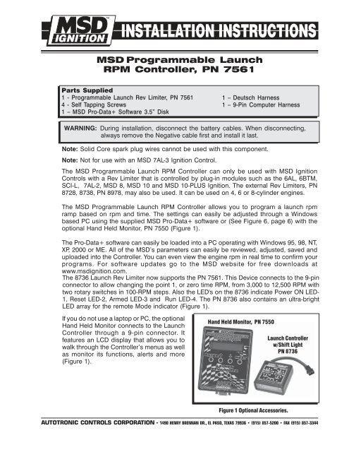
The <strong>MSD</strong> <strong>Pro</strong>grammable Launch RPM Controller allows you to program a launch rpm<br />
ramp based on rpm and time. The settings can easily be adjusted through a Windows<br />
based PC using the supplied <strong>MSD</strong> <strong>Pro</strong>-Data+ software or (See Figure 6, page 6) with the<br />
optional Hand Held Monitor, PN 7550 (Figure 1).<br />
The <strong>Pro</strong>-Data+ software can easily be loaded into a PC operating with Windows 95, 98, NT,<br />
XP, 2000 or ME. All of the <strong>MSD</strong>’s parameters can easily be reviewed, adjusted, saved and<br />
uploaded into the Controller. You can even view the engine rpm in real time to confirm your<br />
programs. For software updates go to the <strong>MSD</strong> website for free downloads at<br />
www.msdignition.<strong>com</strong>.<br />
The 8736 Launch Rev Limiter now supports the PN 7561. This Device connects to the 9-pin<br />
connector to allow changing the point 1, or zero time RPM, from 3,000 to 12,500 RPM with<br />
two rotary switches in 100-RPM steps. Also the LED's on the 8736 indicate Power ON LED-<br />
1, Reset LED-2, Armed LED-3 and Run LED-4. The PN 8736 also contains an ultra-bright<br />
LED array for the remote Mode indicator (Figure 1).<br />
If you do not use a laptop or PC, the optional<br />
Hand Held Monitor connects to the Launch<br />
Controller through a 9-pin connector. It<br />
features an LCD display that allows you to<br />
walk through the Controller’s menus as well<br />
as monitor its functions, alerts and more<br />
(Figure 1).<br />
Hand Held Monitor, PN 7550<br />
Launch Controller<br />
w/Shift Light<br />
PN 8736<br />
Figure 1 Optional Accessories.<br />
AUTOTRONIC CONTROLS CORPORATION • 1490 HENRY BRENNAN DR., EL PASO, TEXAS 79936 • (915) 857-5200 • FAX (915) 857-3344
2 INSTALLATION INSTRUCTIONS<br />
PROGRAMMABLE FEATURES<br />
CylCnt<br />
StartUp RevLimit<br />
Reset Sw Gnd<br />
Launch Delay<br />
RevLim Pt 1<br />
Ignition<br />
Monitored Items<br />
LaunchIn<br />
RPM/TIME<br />
RevTime 0.00<br />
Cylinder Count. Select 4, 6 or 8-cylinder engines. Default is 8-cylinder.<br />
This is the RPM Limit that will be active when the engine is<br />
started. <strong>Pro</strong>grammable in 100 rpm increments from 1,000 – 12,500<br />
rpm. Default is 5,000 rpm.<br />
This selects the activation polarity source for the Reset (Lt Blue)<br />
wire. Select either Ground or +12 Volts for activation with a<br />
momentary switch. Default is Ground.<br />
Delay the activation of the RPM/Timer curve. <strong>Pro</strong>grammable from<br />
0.050 – 1.0 second in 0.001 increments. Default is 0.05 second.<br />
The first step of the RPM Limit curve. This is the active limit once the<br />
Light Blue wire is activated.<br />
This selects the Rev Limit type output of the Ignition or Rev Limiter that<br />
is being used. Default is for the <strong>MSD</strong> 7AL-2.<br />
Launch input timed RevLimit begin switch status.<br />
This is the elapsed time of the rev limit. It is displayed in 0.00<br />
second increments up to 12.5 seconds.<br />
RevLim RPM<br />
This is the current rpm rev limit.<br />
Display Default Range<br />
CylCnt 8 4/6/8<br />
Reset Sw Gnd Sw_Gnd Sw_Gnd/Sw_Pwr<br />
StartUp RevLimit 5000 1000-12500 (100 rpm)<br />
LaunDly 0.050 0.050 0.050-1.000 (0.001sec<br />
RevLim Pt 1 1 1-32 (1)<br />
RevLim Time 0.00 0 0-12.50 (0.01 sec)<br />
RevLim Rpm 6000 6000 1000-12500 (100 rpm)<br />
AlertsPer 1 1 1-9 (1)<br />
Ign 7AL2 6AL, SCI-L, 7AL2, (1)<br />
<strong>MSD</strong>8 <strong>MSD</strong>10, <strong>MSD</strong>10-Plus<br />
PN 8728, PN 8938, PN 8978<br />
Alert Messages Led Blink Code<br />
----------------------------------------------------------------<br />
Out Short 2<br />
Rev Plug Lost 3<br />
Figure 2 Default Setting Chart.<br />
AUTOTRONIC CONTROLS CORPORATION • 1490 HENRY BRENNAN DR., EL PASO, TEXAS 79936 • (915) 857-5200 • FAX (915) 857-3344
INSTALLATION INSTRUCTIONS 3<br />
WIRING<br />
The wiring is routed through a 6-pin Deutsch connector.<br />
Violet<br />
Black<br />
Gray<br />
Light Blue<br />
Dark Blue<br />
Orange/Yellow<br />
RPM Module<br />
Connector<br />
(Yellow)<br />
On/Off power. Connect to a switched 12 volt source.<br />
Ground. Connect to battery negative or other good ground source.<br />
Tach Input. Connect to the <strong>MSD</strong> Ignition’s tach output terminal.<br />
Reset Input. Connects to a momentary +12 volts or ground to arm the<br />
rpm/time program.<br />
Launch input wire to +12 volts. When 12 volts is applied the program<br />
rpm/time program is active.<br />
Remote Indicator. This wire will provide a ground to activate a<br />
light to show that the Controller is reset and active.<br />
This plugs into the rev limit socket of the <strong>MSD</strong>. Note: This connector's polarity<br />
is correct only in one direction with the 7AL-2, <strong>MSD</strong> 10 and <strong>MSD</strong> 10-PLUS.<br />
The LED (Figure 3) will confirm that the polarity is connected correctly. With<br />
the wiring connected turn the ignition On. If the LED flashes a code 3 (three<br />
blink-pause sequences) the polarity is reversed. Turn the ignition Off, flip the<br />
rpm module connector 180° and repeat the test. The LED should remain on<br />
constant when the ignition is turned On and polarity is correct.<br />
LED<br />
T<strong>here</strong> is an LED on the side of the unit<br />
that has several uses. When the power is<br />
turned On, the LED will glow steady. Once<br />
the Reset Switch has been reset (Light<br />
Blue wire) it will blink rapidly to indicate<br />
that it is armed. When the Launch switch<br />
is activated (12 volts on the Dark Blue<br />
wire) the LED will go out indicating that<br />
the rpm/time sequence has begun.<br />
Also, the LED will show fault codes. A code<br />
2 (blink-pause-blink) indicates that the<br />
remote indicator wiring (Orange/Yellow)<br />
wire is shorted. The fault blink code will<br />
continue until the fault has been corrected.<br />
The LED will show a fault code 3 indicating:<br />
9-PIN CONNECTION<br />
Figure 3 LED Indicator.<br />
LED<br />
The RPM plug is not connected in the right direction indicating wrong polarity.<br />
The Ignition is not On or it is programmed for the 7AL-2, <strong>MSD</strong> 10, <strong>MSD</strong> 10-PLUS ignitions<br />
which require correct polarity of the RPM limiter plug.<br />
AUTOTRONIC CONTROLS CORPORATION • 1490 HENRY BRENNAN DR., EL PASO, TEXAS 79936 • (915) 857-5200 • FAX (915) 857-3344
4 INSTALLATION INSTRUCTIONS<br />
Figure 4 Wiring with a 7AL-2 Ignition System.<br />
Figure 4 Launch Rev Limit Control Wiring.<br />
Note: The Revlimit Plug Output has polarity (positive and negative terminals) when<br />
connected to the 7AL-2, <strong>MSD</strong> 10 and <strong>MSD</strong> 10-Plus only.<br />
When the RPM Plug is connected in the correct polarity the LED will be on steady.<br />
When the RPM is not connected correctly the LED of the 7561 will blink a fault code (three<br />
blinks-pause-repeat). Either the ignition is not On or the RPM plug is not in the right<br />
direction (RPM Plug is backwards).<br />
AUTOTRONIC CONTROLS CORPORATION • 1490 HENRY BRENNAN DR., EL PASO, TEXAS 79936 • (915) 857-5200 • FAX (915) 857-3344
INSTALLATION INSTRUCTIONS 5<br />
Figure 5 Wiring Two Launch RPM Controls (for second gear control).<br />
Figure 5 Dual Rev Limit Control Wiring for Launch and 2nd Gear.<br />
Note: The Revlimit Plug Output has polarity (positive and negative terminals) when<br />
connected to the 7AL-2, <strong>MSD</strong> 10 and <strong>MSD</strong> 10-Plus only.<br />
When the RPM Plug is connected in the correct polarity the LED will be on steady.<br />
When the RPM is not connected correctly the LED of the 7561 will blink a fault code (three<br />
blinks-pause-repeat). Either the ignition is not On or the RPM plug is not in the right<br />
direction (RPM Plug is backwards).<br />
AUTOTRONIC CONTROLS CORPORATION • 1490 HENRY BRENNAN DR., EL PASO, TEXAS 79936 • (915) 857-5200 • FAX (915) 857-3344
6 INSTALLATION INSTRUCTIONS<br />
PRO-DATA+ PROGRAMMING INSTRUCTIONS<br />
INSTALLING THE SOFTWARE<br />
1. Insert the installation disk.<br />
2. In Windows click Start then select Run.<br />
3. In the box type A:\Setup then press Enter.<br />
4. Follow the on-screen instructions.<br />
5. At this point t<strong>here</strong> should be two <strong>MSD</strong> icons on your desktop.<br />
6. Select the one that says <strong>MSD</strong> Graph View.<br />
7. In the upper left corner of the screen select File.<br />
8. Select the folder 7561.<br />
9. Select the file that says 7561vXX.IGN (XX means the latest version such as 02).<br />
10. Click on Open.<br />
SAVES AND TRANSFERS<br />
Whenever a change is made to a program it either must be saved to your PC as part of the<br />
file you are programming or it must be Saved/Transferred to the <strong>MSD</strong> Controller. The software<br />
gives you the choice of automatically transferring the change to the <strong>MSD</strong> or the PC.<br />
Save to <strong>MSD</strong>: By saving the change right to the <strong>MSD</strong>, the new change is automatically put<br />
into the Controller.<br />
Save to PC: This saves the changes on your PC screen only. The information still must be<br />
transferred to the <strong>MSD</strong> before it be<strong>com</strong>es active or saved to a file.<br />
TACHOMETER<br />
The tachometer on the monitor screen will show real time rpm and the timing retard when<br />
the engine is running with the laptop connected.<br />
SECONDS<br />
MONITORED ITEMS<br />
USER NOTES<br />
RPM LIMIT CURVE<br />
PROGRAM<br />
LADDER<br />
RPM<br />
TIME<br />
Figure 6 <strong>Pro</strong>-Data+ Software Screen.<br />
AUTOTRONIC CONTROLS CORPORATION • 1490 HENRY BRENNAN DR., EL PASO, TEXAS 79936 • (915) 857-5200 • FAX (915) 857-3344
INSTALLATION INSTRUCTIONS 7<br />
HAND HELD MONITOR<br />
If you are using the optional Hand Held Monitor to program this Controller, Figure 7 shows<br />
the <strong>com</strong>plete menu screens.<br />
Figure 7 Hand Held Monitor Screen Menu.<br />
Figure 8 Time Line of Operation Sequence.<br />
AUTOTRONIC CONTROLS CORPORATION • 1490 HENRY BRENNAN DR., EL PASO, TEXAS 79936 • (915) 857-5200 • FAX (915) 857-3344
Service<br />
In case of malfunction, this <strong>MSD</strong> <strong>com</strong>ponent will be repaired free of charge according to the terms of<br />
the warranty. When returning <strong>MSD</strong> <strong>com</strong>ponents for service, <strong>Pro</strong>of of Purchase must be supplied for warranty<br />
verification. After the warranty period has expired, repair service is charged based on a minimum and<br />
maximum charge.<br />
Send the unit prepaid with proof of purchase to the attention of: Customer Service Department,<br />
Autotronic Controls Corporation, 12120 Esther Lama, Suite 114, El Paso, Texas 79936.<br />
When returning the unit for repair, leave all wires at the length in which you have them installed. Be<br />
sure to include a detailed account of any problems experienced, and what <strong>com</strong>ponents and accessories<br />
are installed on the vehicle.<br />
The repaired unit will be returned as soon as possible after receipt, COD for any charges. (Ground<br />
shipping is covered by warranty). All units are returned regular UPS unless otherwise noted. For more<br />
information, call the <strong>MSD</strong> Customer Service Line (915) 855-7123. <strong>MSD</strong> technicians are available from 8:00<br />
a.m. to 5:00 p.m. Monday - Friday (mountain time).<br />
Limited Warranty<br />
Autotronic Controls Corporation warrants <strong>MSD</strong> Ignition products to be free from defects in material<br />
and workmanship under normal use and if properly installed for a period of one year from date of<br />
purchase. If found to be defective as mentioned above, it will be replaced or repaired if returned prepaid<br />
along with proof of date of purchase. This shall constitute the sole remedy of the purchaser and the sole<br />
liability of Autotronic Controls Corporation. To the extent permitted by law, the foregoing is exclusive<br />
and in lieu of all other warranties or representations whether expressed or implied, including any implied<br />
warranty of merchantability or fitness. In no event shall Autotronic Controls Corporation be liable for<br />
special or consequential damages.<br />
AUTOTRONIC CONTROLS CORPORATION • 1490 HENRY BRENNAN DR., EL PASO, TEXAS 79936 • (915) 857-5200 • FAX (915) 857-3344<br />
FRM23500 Created 10/02 Printed In U.S.A.