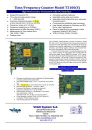
Time/Frequency Counter Model T3200U - VIGO System SA
Time/Frequency Counter Model T3200U - VIGO System SA
Time/Frequency Counter Model T3200U - VIGO System SA

Create successful ePaper yourself
Turn your PDF publications into a flip-book with our unique Google optimized e-Paper software.
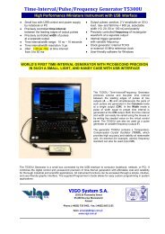
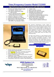
<strong>Time</strong>/<strong>Frequency</strong> <strong>Counter</strong> <strong>Model</strong> <strong>T3200U</strong><br />
High Performance Miniature Instrument with USB Interface<br />
Small box with USB control and supply<br />
by notebook, netbook, or PC<br />
<strong>Time</strong> interval measurement range:<br />
0 – 4400 seconds<br />
Precision (standard deviation) < 35 ps<br />
at time interval from 0 to 100 ms<br />
<strong>Frequency</strong> range up to 3.5 GHz<br />
<strong>Frequency</strong> sampling up to 2 MSa/s<br />
Measurement of Allan Deviation (ADEV)<br />
Measurement of <strong>Time</strong> Interval Error<br />
(TIE, MTIE), <strong>Time</strong> Deviation (TDEV)<br />
<br />
<br />
<br />
<br />
<br />
<br />
<br />
Totalize mode<br />
Built-in automatic calibrator<br />
Selectable pulse edge and polarity<br />
Selectable input threshold level<br />
or automatic threshold search<br />
Comprehensive statistical data processing<br />
User-friendly software for Windows<br />
and DLL file for user’s applications<br />
Export of data files for processing<br />
in other programs (Stable32, MS Excel)<br />
The advanced <strong>Time</strong>/<strong>Frequency</strong> <strong>Counter</strong> <strong>T3200U</strong> is<br />
contained in a small, light, and handy case connected by the<br />
USB 2.0 interface to computer (notebook, netbook, or PC). It<br />
combines a 35 ps precision (RMS) of single-shot timeinterval<br />
measurement with affordable cost and reliability for<br />
mobile applications in industry and research laboratories.<br />
The supplied software creates a user-friendly graphic<br />
interface and provides flexible control and display of the<br />
measurement data.<br />
The heart of the instrument is a newly developed counter<br />
chip, which contains an interpolation time counter with two<br />
precise two-stage <strong>Time</strong>-to-Digital Converters, a FIFO<br />
memory which allows for high measurement rate, and a<br />
dedicated microcontroller. The counter <strong>T3200U</strong> contains a<br />
Temperature-Compensated Crystal Oscillator (TCXO) which<br />
provides high accuracy and stability at reasonable cost.<br />
Buy together with the precise<br />
<strong>Time</strong>-Interval/Pulse/<strong>Frequency</strong> Generator T5300U<br />
at a bargain price!<br />
▼<br />
<br />
<br />
<br />
<br />
<br />
<br />
<br />
Precisely controlled time interval between the leading edges<br />
of output pulses, and the pulse width<br />
<strong>Time</strong> interval/width range: 10 ns – 10 seconds, 5 ps resolution<br />
Jitter: < 20 ps rms at time interval from 10 ns to 50 ms<br />
Internal trigger generator: 10 mHz to 1 MHz<br />
<strong>Frequency</strong> synthesizer produces rectangular pulses with frequency<br />
variable from 0.1 Hz to 75 MHz<br />
Output pulses: positive, 2 V amplitude on 50 Ω load, rise- and fall<br />
time < 600 ps, selectable width (10, 20, 50, 100 ns) and polarity<br />
Clock generator: internal TCXO or external 10 MHz reference clock<br />
<strong>VIGO</strong> <strong>System</strong> S.A.<br />
129/133 Poznanska Street<br />
05-850 Ozarow Mazowiecki<br />
Poland<br />
Phone: (+4822) 733 5405, Fax: (+4822) 665 2155<br />
Sales: amaciak@vigo.com.pl<br />
www.vigo.com.pl
◄ 14-digit resolution in <strong>Time</strong> Interval mode<br />
▼ Precision (Standard Deviation of TI measurements)<br />
Functions<br />
Statistics<br />
Graphics<br />
<strong>Time</strong> Interval<br />
Specifications<br />
Range 0 – 4400 seconds (Inputs A and B)<br />
Resolution (LSB)<br />
Precision (Standard Deviation)<br />
<strong>System</strong>atic Error<br />
Range Limit (Overflow)<br />
Start Enable<br />
Stop Disable<br />
Dead <strong>Time</strong><br />
Measurement Rate<br />
<strong>Time</strong> Interval (between two pulses at two inputs or pulses appearing consecutively at a single, common<br />
input), Period, Pulse Width, <strong>Frequency</strong>, <strong>Frequency</strong> Sampling, Allan Deviation, <strong>Time</strong> Interval Error (TIE),<br />
Maximum TIE (MTIE), <strong>Time</strong> Deviation (TDEV), Totalize<br />
Mean, Min and Max Values, Standard Deviation<br />
Tables and plots of statistical distributions, display of frequency sampling in time domain to show possible<br />
frequency variation (Sampling mode)<br />
25 ps in single-shot measurements, may be reduced with averaging<br />
< 35 ps at time interval measured from 0 to 100 ms<br />
< 35 ps at time interval measured from 0 to 1 second, when using an atomic clock as external clock<br />
< 35/ Sample _ Size ps with averaging<br />
< (1 ns max + (<strong>Time</strong>base Error x Interval) + Trigger Level Timing Error)<br />
presettable: 1 s, 10 s, 100 s, 4400 s<br />
internal (controlled by software)<br />
referred to Start, internally programmable over the range (1…999)·20 units; unit = ns, µs, ms<br />
200 ns<br />
up to 5·10 6 measurements per second<br />
(when measuring zero time interval and storing data in internal FIFO memory),<br />
up to 5·10 4 measurements per second stored to memory in PC<br />
<strong>Frequency</strong> & Period<br />
Range Inputs A and B: 0.1 Hz to 200 MHz<br />
Sensitivity < 75 mV RMS typ. (0.01 to 200 MHz); Minimum slew rate: 10 V/µs<br />
Input F: 100 MHz to 3.5 GHz<br />
Sensitivity < -12 dBm (< 55 mV RMS) from 400 MHz to 3 GHz<br />
Sensitivity < - 3 dBm (< 160 mV RMS) from 100 MHz to 3.5 GHz<br />
Gate <strong>Time</strong><br />
Dead <strong>Time</strong><br />
Measurement Rate<br />
selected from 1 μs to 10 s (reciprocal method)<br />
200 ns + 2 periods of tested signal<br />
up to 8·10 5 measurements/sec<br />
(when measuring frequency in 1 μs gate and storing data in internal FIFO memory)<br />
up to 3.3·10 4 measurements/sec stored to memory in PC<br />
<strong>Frequency</strong> Sampling<br />
Range Inputs A and B: 1 to 200 MHz<br />
Input F: 100 MHz to 3.5 GHz<br />
Sampling Rate<br />
0.1, 0.2, 0.5, 1.0, 2.0 MSa/s<br />
Totalize<br />
Range<br />
Input frequency<br />
Gate <strong>Time</strong><br />
0 to 10 12 counts<br />
max. 200 MHz<br />
Internal: from 1 μs to 10 s, Manual Start-Stop<br />
Inputs A and B Impedance: 50 , DC coupled; SMA sockets<br />
Amplitude: within 4 V<br />
Pulse edge: selectable, rising or falling<br />
Threshold: manually adjustable from -4 V to +4 V with 40 mV resolution, or set automatically<br />
Internal Clock Generator<br />
10 MHz TCXO, stability 5×10 -7 (- 40 to +85 C),<br />
ageing 1×10 -6 /year<br />
External Clock Generator<br />
10 MHz, min. 100 mV on 50 input impedance,<br />
DC coupled; SMA socket<br />
Capacity of FIFO Memory<br />
4 K time/delay measurements, 2.5 K frequency measurements<br />
USB receptacle Type B, USB 2.0<br />
Power Supply<br />
Supplied Software<br />
Size<br />
Weight<br />
provided by the USB 2.0 interface, Y cable supplied<br />
for Windows ® XP/Vista/7, DLL file for other applications<br />
135 (L) × 70 (W) × 17 (H) mm<br />
160 g
Architecture<br />
The main inputs for time-interval and frequency measurement are A<br />
and B. The fast comparators (FC) allow to select the required threshold<br />
level of the input pulses. The voltage levels are set by the<br />
corresponding Digital-to-Analog Converters (DAC) and can be adjusted<br />
manually on the virtual desktop or automatically by the software<br />
procedure.<br />
The standardized pulses from the comparator outputs are fed to the<br />
interpolation time counter. The counter can measure the time intervals<br />
in the range from 0 to 4400 seconds with a 25 ps resolution, or<br />
measure the frequency of input pulses up to 200 MHz. To increase that<br />
range a fast frequency divider enlarges the maximum frequency range<br />
to 3.5 GHz at the F input.<br />
The counter <strong>T3200U</strong> was designed with two precise, two-stage<br />
interpolators integrated in the counter chip which contains also the<br />
FIFO memory, two correction look-up tables (LUTs) and a dedicated<br />
microcontroller.<br />
The on-board calibration generator is used during the calibration<br />
routine to compensate the input time offset between the channels A<br />
and B, and to identify the transfer characteristics of two two-stage<br />
interpolators contained in the counter. The calibration pulses are<br />
applied through the solid-state relays to the inputs A and B<br />
simultaneously.<br />
Measurement of <strong>Time</strong> Interval<br />
The Start and Stop pulses are applied to the inputs A<br />
and B with selected edge (rising - ↑ or falling - ↓). The<br />
time interval can also be measured between the edges<br />
of two consecutive pulses appearing at a single input.<br />
The Threshold at the inputs A and/or B may be set<br />
manually on any level between – 4 V and + 4 V, or<br />
may be set at the fixed TTL level (+1.5 V) or a selected<br />
CMOS level (+1.25 V, +1.65 V or +2.5 V). The “best”<br />
threshold level (in the middle of the amplitude) can also<br />
be adjusted automatically (Auto mode).<br />
To enable the STOP pulse (at the A or B input), an<br />
internal programmable counter can be utilized to set the<br />
needed STOP disable time (after the leading edge of<br />
the START pulse) over a range (1…999)·20 units,<br />
where the unit is selected as ns, µs, or ms.<br />
In some practical cases, the Start pulse begins the<br />
measurement of time interval, but the Stop pulse does<br />
not appear. To avoid long waiting time for overflow in<br />
the nominal range (4400 seconds) you can lower the<br />
overflow limit by setting the maximum Range. You can<br />
select the values 1 s, 10 s, 100 s, or 4400 s. By default the Range equals 1 second. The selected range is also shown in the upper<br />
right corner of the display panel.<br />
To achieve high versatility of the counter in many applications also the Length of the Session may be preset by ticking the mark<br />
(√) at the Length option and writing the desired value of the session length in the corresponding field.<br />
Averaging is accomplished by execution of measurements in a preset Sample. For a Sample Size equal to n, the standard<br />
deviation of the resulting mean value is StdDev/√n. If StdDev = 30 ps and n = 100, then the standard deviation of the mean value<br />
is 50/10 = 3 ps.<br />
The Pulse Width mode allows for measurement of pulse width of pulses applied to the input A or B. The polarity of pulses<br />
(active edges), threshold level, and measurement session are defined in the same way as in the <strong>Time</strong> Interval mode.<br />
See the behavior of precision versus time interval (seldom presented by other manufacturers) shown on the previous page.
Measurement of <strong>Frequency</strong><br />
The inputs A and B can be used for frequency measurements (using<br />
reciprocal method) up to 200 MHz, while the input F accepts signals from<br />
100 MHz up to 3.5 GHz.<br />
Period In this mode the measurements are performed in a similar fashion<br />
as in the <strong>Frequency</strong> mode.<br />
Totalize In this mode the input pulses are counted within a preset time<br />
gate. The duration of the gate may be selected in the Gate window as 1<br />
μs, 10 μs, 100 μs, 1 ms, 10 ms, 100 ms, 1 s, and 10 s, or not set (Gate<br />
Open). For each gate the number of counted pulses (main result) and the<br />
respective Mean <strong>Frequency</strong> (below) in pulses per second are displayed.<br />
<strong>Frequency</strong> sampling<br />
The sampling mode allows for discovering a frequency variation or<br />
modulation (needed or not) of the measured signal. Thanks to the short<br />
dead time of the counter, the frequency sampling can be performed at an<br />
internally generated rate ranging from 100 kSa/s up to 2 MSa/s.<br />
The lowest value of the sampled frequency depends on the selected<br />
sampling rate. The lowest sampling rate results in a minimum random<br />
error, while the highest sampling rate allows for maximum resolution to<br />
observe rapid changes in the sampled frequency.<br />
◄ The screen snapshot was obtained for a 50 MHz signal from the<br />
HP8648 signal generator, with a 1 kHz frequency modulation.<br />
Allan Deviation<br />
A commonly used measure of the short-time stability of periodic signals is<br />
the Allan Deviation (ADEV). The counter T3100 has built-in this feature.<br />
The measurements may also be performed in the Sequence mode,<br />
where the results are displayed in the list form and as a graph, for a<br />
sequence of observation intervals with different values of τ. The σ y (τ)<br />
measurement begins with a selected value of τ from a preset set and<br />
ends with another selected value of τ. The resulting data sequence is<br />
displayed in the real time on the screen.<br />
Measurement of frequency wander – <strong>Time</strong> Interval Error (TIE)<br />
and Maximum TIE (MTIE)<br />
Wander usually results from the frequency offset or changes in cable delay<br />
due to temperature variation and can lead to data slips in communication<br />
systems. To guarantee network synchronization quality, the wander should<br />
be kept within the secure limits defined in respective standards. An<br />
important parameter characterizing the wander is the <strong>Time</strong> Interval Error<br />
(TIE). The maximum value of TIE (MTIE), computed from an array of TIE<br />
data, can characterize the frequency offsets and phase transients of a<br />
tested signal to obtain a clear view of quality of relevant electronic<br />
apparatus or systems.<br />
The resulting data may also be arranged on display in the list form or as a<br />
graph. In addition, the <strong>Time</strong> Deviation (TDEV) is computed.<br />
Storing and processing of measurement data<br />
The measurement results are first stored in the FIFO memory and then transmitted to PC and stored in a file located on the hard<br />
disk or another nonvolatile memory. The names of respective files and folders are conveniently arranged for easy reviewing and<br />
identification of measurement sessions.