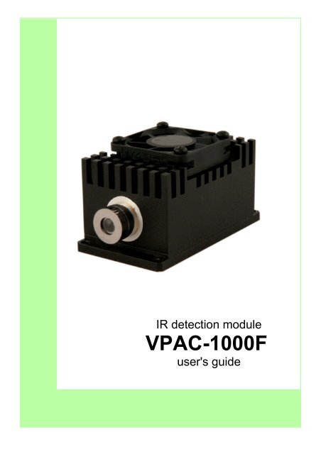
VPAC-1000F user\'s guide.pdf - VIGO System SA
VPAC-1000F user\'s guide.pdf - VIGO System SA
VPAC-1000F user\'s guide.pdf - VIGO System SA

You also want an ePaper? Increase the reach of your titles
YUMPU automatically turns print PDFs into web optimized ePapers that Google loves.
2. <strong>VPAC</strong>-<strong>1000F</strong> technical informationThe <strong>VPAC</strong>-<strong>1000F</strong> module consists of:• Detector TE cooled or uncooled,• Transimpedance preamplifier optimized for required responsivity and bandwidth.2.1. Module physical dimensionsM8x1 threaded hole is intended to installthe DRB-1 heat sink base.Dimensions are given in millimeters129/133 Poznanska St., 05-850 Ozarow Mazowiecki, Poland; tel. +48 22 733 54 20; fax +48 22 733 54 26; e-mail: info@vigo.com.pl 4Please note: the information contained in this document is subject to change without further notification. <strong>VIGO</strong> <strong>System</strong> reserves the right to alter the performance and any resulting specifications.VS- 11-08-10MB
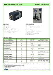
Cooling fanSMA signaloutput connectorIR detectorSupply, TEC andThermoresistorLEMO connector2.2. Beam power limitationIR DetectorParameter immersed without immersionMaximum continuous optical power 2.5 W/cm 2 100W/cm 2Maximum optical power of pulses shorter than 1µs 10 kW/cm 2 1MW/cm 2• For repeated IR radiation with pulses shorter than 1 μs, the equivalent CW irradiation power, averaged overthe pulse - to - pulse period, should be less than the CW damage threshold according to equation:pulse peak powerequivalent CW radiation= ∗pulse duration∗repetition ratedetector active area• Saturation thresholds vary by detector type and can be provided upon request.129/133 Poznanska St., 05-850 Ozarow Mazowiecki, Poland; tel. +48 22 733 54 20; fax +48 22 733 54 26; e-mail: info@vigo.com.pl 5Please note: the information contained in this document is subject to change without further notification. <strong>VIGO</strong> <strong>System</strong> reserves the right to alter the performance and any resulting specifications.VS- 11-08-10MB
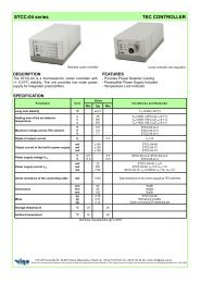
2.3. Preamplifier supply voltage<strong>VPAC</strong>-<strong>1000F</strong> module requires + 12 V / - 5 V / 100 mA for supply.The module is internally protected against reversing the supply polarity and abnormal voltage increase. Althoughmodule contains voltage regulators, while powering with the custom made power supply, provide the properlystabilized and filtered voltage.2.4. Preamplifier load resistanceLoad resistance of the <strong>VPAC</strong>-100F module must be exactly 50 Ω.Terminating with incorrect load resistance would lead to:• voltage response that will not match the value given in the datasheet,• preamplifier pulse response distortion to the line reflection.2.5. Thermoelectric cooler parametersCooler type Maximum voltage [V] Maximum current [A]2-TE (two stage cooler) 1.3 1.23-TE (three stage cooler) 3.6 0.454-TE (four stage cooler) 8.3 0.5Shown above parameters matters in case of using <strong>VPAC</strong>-<strong>1000F</strong> module in custom made systems. TECparameters may be changed without notification.2.6. ThermistorThermistor (with the output pins available as TH1 and TH2) is the NTC component (negative temperaturecoefficient) and it is necessary to lock the temperature control loop-back for keeping the inside temperature constant.The resistance value, when the nominal detector temperature is achieved, is given in the datasheet.129/133 Poznanska St., 05-850 Ozarow Mazowiecki, Poland; tel. +48 22 733 54 20; fax +48 22 733 54 26; e-mail: info@vigo.com.pl 6Please note: the information contained in this document is subject to change without further notification. <strong>VIGO</strong> <strong>System</strong> reserves the right to alter the performance and any resulting specifications.VS- 11-08-10MB
2.7. Supply socket812793654LEMODescriptionPin numberFAN + 1Thermistor1 2TEC+ 3+V CC 4GND 5-V EE 6TEC- 7Thermistor2 8Not connected 9129/133 Poznanska St., 05-850 Ozarow Mazowiecki, Poland; tel. +48 22 733 54 20; fax +48 22 733 54 26; e-mail: info@vigo.com.pl 7Please note: the information contained in this document is subject to change without further notification. <strong>VIGO</strong> <strong>System</strong> reserves the right to alter the performance and any resulting specifications.VS- 11-08-10MB
3. Getting started (regards the module itself as well as thecomplete IR detecting kit)3.1. Unpackingthe distributor.Before unpacking, verify if there are no visible damages of the package. Report them to the manufacturer or3.2. Installation & connections• Mount the IR module in the measurement setup,• Connect all elements with cables provided in the package,• Make sure that all the elements are properly connected.The picture shown below presents sample IR detecting kit configuration with interconnections.<strong>VPAC</strong>-<strong>1000F</strong>DB9 – LEMO cablePower supplySMA-BNC cableDRB-1 standSTCC-04129/133 Poznanska St., 05-850 Ozarow Mazowiecki, Poland; tel. +48 22 733 54 20; fax +48 22 733 54 26; e-mail: info@vigo.com.pl 8Please note: the information contained in this document is subject to change without further notification. <strong>VIGO</strong> <strong>System</strong> reserves the right to alter the performance and any resulting specifications.VS- 11-08-10MB
3.3. Switching on procedure• Do not switch on the IR module power supply until ALL elements of the IR detection kit are properly connectedwith the proper cables.• Switch on the thermoelectric cooler controller and wait until detector operating temperature is reached andstabilized. Ready state will be indicated by the „LOCK” green LED light.• Before starting the measurements make sure the load resistance is valid. The <strong>VPAC</strong>-<strong>1000F</strong> output should beterminated by 50 Ω resistance.• Do not manipulate any connectors on the active IR kit – this may introduce additional noises to the system orcan cause severe damages due to electrostatic discharges.129/133 Poznanska St., 05-850 Ozarow Mazowiecki, Poland; tel. +48 22 733 54 20; fax +48 22 733 54 26; e-mail: info@vigo.com.pl 9Please note: the information contained in this document is subject to change without further notification. <strong>VIGO</strong> <strong>System</strong> reserves the right to alter the performance and any resulting specifications.VS- 11-08-10MB
4. <strong>VPAC</strong>-<strong>1000F</strong> other related information4.1. CE statement of conformity<strong>VIGO</strong> <strong>System</strong> declares that IR detection kit is fully compliant with:EU Low Voltage Directives: 73/23/EEC, 93/68/EECEU Electromagnetic Compatibility Directives: 89/336/EEC, 91/263/EEC, 92/31/EEC, 93/68/EEC4.2. Electromagnetic interferenceTo avoid the electromagnetic interferences (EMI), please do not put any electromagnetic source close to theIR module. That may cause interference to the input of the preamplifier and disturb the useful signal in the IR track4.3. Operating temperature and heat sinkingThe detector being a part of the module produces heat due to the radiation sensitive structure cooling. Caseof the <strong>VPAC</strong>-<strong>1000F</strong> module provides complete heat dissipation and doesn't require any additional external radiatornor fan. However, detector specifications are guaranteed for the environment temperature not exceeding 35 O C.4.4. Storage informationTo ensure reliable operation and long lifetime of detector, the following conditions should be fulfilled:• Storage temperature: -10ºC ÷ + 50ºC and 10% to 90% humidity• Avoid exposing to direct sunlight and strong UV/VIS light as this may result in degradation of a detector performance• Avoid electrostatic discharges (ESD)129/133 Poznanska St., 05-850 Ozarow Mazowiecki, Poland; tel. +48 22 733 54 20; fax +48 22 733 54 26; e-mail: info@vigo.com.pl 10Please note: the information contained in this document is subject to change without further notification. <strong>VIGO</strong> <strong>System</strong> reserves the right to alter the performance and any resulting specifications.VS- 11-08-10MB
5. Safety instructionsTo ensure safe and failure-free operation of the IR detection kit comply with the following precautions:The IR module is dedicated to measure IR flux. Never use the module in other applicationsNever dismount the case or heat sink of the module. Do not open or remove the housing of the device. It maylead to its permanent damage or/and to a risk of electric shockHandle with care, avoid excessive mechanical shock or vibration. Excessive mechanical stress applied to thepackage itself or to a device containing the package may result in permanent damage. Peltier element usedas TEC in thermoelectrically cooled detectors is susceptible to mechanical shocks. Great care should betaken when handling cooled detectors.Use the proper cables to connect elements of the kit, dedicated for specified device only. Never cut or shortenany cable, it may cause damage to your device.Never use cables not approved by <strong>VIGO</strong> <strong>System</strong>.Do not replace parts of the IR detection kit - cables, preamplifiers, TEC controllers or detectors. Using partsfrom other IR detection kit can be the cause of malfunction of your module.Never touch the detector window.Do not insert any objects inwards the vents of the housing. Covering or closing the vents or cooling fan maycause a dangerous rise of the temperature inside the module.All connectors must be connected carefully and firmly.Avoid damp locations. The IR module should be neither installed nor used in high humidity locations.Avoid locations with ambient temperature exceeding module operating temperature. The IR module shouldnot be installed in the proximity of radiators, heat outlets, burners or other heat emitting objects.Use proper ESD protectionEnsure stable placement of the device. The IR module should stand on a stable surface.Some IR detector window materials such as BaF 2 are soft. Particular attention should be paid not to scratchthe surface of the window. A damaged window may entirely degrade the detector performance.Important note!If you are setting up own system based on IR detector module without TEC controller or power supply,please check if the TEC current/voltage and power supply are correct.129/133 Poznanska St., 05-850 Ozarow Mazowiecki, Poland; tel. +48 22 733 54 20; fax +48 22 733 54 26; e-mail: info@vigo.com.pl 11Please note: the information contained in this document is subject to change without further notification. <strong>VIGO</strong> <strong>System</strong> reserves the right to alter the performance and any resulting specifications.VS- 11-08-10MB
6. TroubleshootingAt first, please carefully read the previous parts of this manual, especially Safety Instructions. If a problempersists, please check the information given below.General Test ProcedureCheck:• Whether components of your IR detection kit are connected correctly,• Whether connections are snug-tight,• Whether supply voltages or currents of the components are consistent with the specification,• Whether an appropriate detector operating temperature is achieved (proper thermistor resistance or indicatorson the TEC controller),• Attenuation/gain factors in your measurement set-up,• Load resistance at the preamplifier output,• For high frequency (> 20 MHz) output line, and the load must be matched to the 50 Ohm preamplifier output,• Whether bandwidths of the components are reasonably well-matched to each other,• Whether the detector is not saturated or damaged by too high irradiation. Refer to Beam Power Limitationssection of this manual. If a problem still exists, try to identify and solve it by actions mentioned below.• Cycle the power of the components off and on again• After shielding/switching off the radiation source, do you see any signal decrease? If yes, most probably yousee a signal from the optical radiation you hope to see.6.1. List of the possible faults and solutions6.1.1. The LOCK LED on the TEC controller’s does not lightFollow through General Test Procedure.Check:• Thermistor resistance or indicators on the TEC controller,• Ambient temperature, whether it is not higher than the maximal allowed for a given detector/module operatingtemperature,• Supply voltages and currents of the TEC controller,129/133 Poznanska St., 05-850 Ozarow Mazowiecki, Poland; tel. +48 22 733 54 20; fax +48 22 733 54 26; e-mail: info@vigo.com.pl 12Please note: the information contained in this document is subject to change without further notification. <strong>VIGO</strong> <strong>System</strong> reserves the right to alter the performance and any resulting specifications.VS- 11-08-10MB
• TEC controller circuitry and set-point connection,• detector sealing; is condensation or ice deposition seen on detector element or elsewhere?If the operating temperature is still higher than expected or the detector package is unsealed, contact yourtechnical support.6.1.2. Too high DC level at the output of the preamplifierFollow through General Test Procedure.Remove the IR source from the detector field of view or decrease incident beam power of your IR source. Ifdevice still has high DC level, contact your technical support.6.1.3. Too high current consumption by the preamplifierThe device is probably damaged, contact your technical support.6.1.4. No or too weak response to optical radiationFollow through General Test Procedure.• Check your radiation source,• If you do not have any other detector to test your radiation source, move a hot object (ex. soldering iron) rapidlyin front of the detector, across its whole field of view. (The higher the temperature of the object or shorterthe distance to the detector, the higher the optical signal at the detector output.),• Test your detector with another available radiation source. A warm or hot object moved in front of the detectorcan be used for DC or low frequency AC coupled devices,• Align or improve your optical setup for the maximized signal or signal-to-noise ratio,• Estimate the detector response, taking into account the incident radiation at the detector active area and theresponsivity of the detector (or of the IR detector module), and check it against measured values,• Evaluate the noise in the system. Calculate the noise introduced by the detector or detection module basingon their noise density from their data sheets. Check it against measured response of the blinded detector,• Check if the incident radiation will be strong enough to obtain sufficient signal-to-noise ratio. (A signal is easyto pick out of a noise when its peak to peak value is several times greater than of the noise.) If it is lowerthan expected, consider increasing the incident radiation power on the detector active area,• Check also if the incident radiation is not too strong, causing detector saturation or damage. If you cannotobtain signal sufficiently higher than noise, contact your technical support.129/133 Poznanska St., 05-850 Ozarow Mazowiecki, Poland; tel. +48 22 733 54 20; fax +48 22 733 54 26; e-mail: info@vigo.com.pl 13Please note: the information contained in this document is subject to change without further notification. <strong>VIGO</strong> <strong>System</strong> reserves the right to alter the performance and any resulting specifications.VS- 11-08-10MB
6.1.5. Excess noiseFirst of all check through General Test Procedure.Excess noise may be caused by poor connections, ground connections and ground loops, high backgroundphoton flux or EMI (ex. inductive motors driving radiation chopper). You may also decrease the noise by reducingyour system bandwidth,If you are unable to identify external excess noise source, contact your technical support.6.1.6. Unstable signalFollow through General Test Procedure.Check:• Cables,• Radiation sources ,• Whether temperature set-point was achieved (TE-cooled devices),• If the device is still unstable, contact your technical support.Warning - DC or low frequency signal may vary due to fluctuations of thermal background radiation6.1.7. Long signal rise/fall timeFollow through General Test Procedure.Check:• The shape of the pulse with another detector if possible,• The operating conditions (detector temperature, bias, optical setup),• If impedance of the detector, cables, preamplifier and your read-out instrument are matched.129/133 Poznanska St., 05-850 Ozarow Mazowiecki, Poland; tel. +48 22 733 54 20; fax +48 22 733 54 26; e-mail: info@vigo.com.pl 14Please note: the information contained in this document is subject to change without further notification. <strong>VIGO</strong> <strong>System</strong> reserves the right to alter the performance and any resulting specifications.VS- 11-08-10MB