TG50Ex-V2_0-00- Prospekt - Martens Elektronik GmbH
TG50Ex-V2_0-00- Prospekt - Martens Elektronik GmbH
TG50Ex-V2_0-00- Prospekt - Martens Elektronik GmbH

Create successful ePaper yourself
Turn your PDF publications into a flip-book with our unique Google optimized e-Paper software.
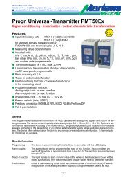
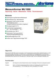
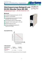
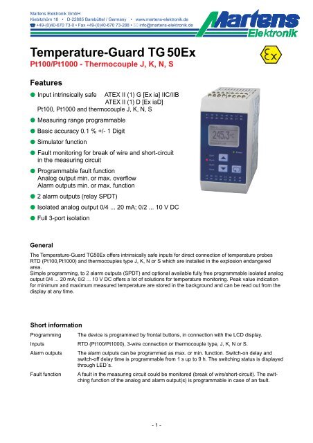
Temperature-Guard TG 50Ex<br />
Pt1<strong>00</strong>/Pt1<strong>00</strong>0 - Thermocouple J, K, N, S<br />
Features<br />
M Input intrinsically safe ATEX II (1) G [Ex ia] IIC/IIB<br />
ATEX II (1) D [Ex iaD]<br />
Pt1<strong>00</strong>, Pt1<strong>00</strong>0 and thermocouple J, K, N, S<br />
M Measuring range programmable<br />
M Basic accuracy 0.1 % +/- 1 Digit<br />
M Simulator function<br />
M Fault monitoring for break of wire and short-circuit<br />
in the measuring circuit<br />
M Programmable fault function<br />
Analog output min. or max. overflow<br />
Alarm outputs min. or max. function<br />
M 2 alarm outputs (relay SPDT)<br />
M Isolated analog output 0/4 ... 20 mA; 0/2 ... 10 V DC<br />
M Full 3-port isolation<br />
General<br />
The Temperature-Guard <strong>TG50Ex</strong> offers intrinsically safe inputs for direct connection of temperature probes<br />
RTD (Pt1<strong>00</strong>,Pt1<strong>00</strong>0) and thermocouples type J, K, N or S which are installed in the explosion endangered<br />
area.<br />
Simple programming, to 2 alarm outputs (SPDT) and optional available fully free programmable isolated analog<br />
output 0/4 ... 20 mA; 0/2 ... 10 V DC offers a lot of solutions for temperature monitoring. Peak value indication<br />
for minimum and maximum measured temperature are stored in the background and can be read out from the<br />
display at any time.<br />
Short information<br />
Programming The device is programmed by frontal buttons, in connection with the LCD display.<br />
Inputs RTD (Pt1<strong>00</strong>/Pt1<strong>00</strong>0), 3-wire connection or thermocouple type, J, K, N or S.<br />
Alarm outputs The alarm outputs can be programmed as max. or min. function. Switch-on delay and<br />
switch-off delay time is programmable from 1 s up to 9 h. The switching status is displayed<br />
through LED´s.<br />
Fault function A fault in the measuring circuit could be monitored (break of wire/short-circuit). The switching<br />
function of the analog and alarm output(s) is programmable in case of an fault.<br />
- 1 -
Technical data<br />
Power supply<br />
Supply voltage : 230 V AC ±10 %, 115 V AC ±10 %, or 24 V DC ±15 %<br />
Um 253 V AC or 125 V DC<br />
(Terminals 11 and 13)<br />
Power consumption : max. 5 VA<br />
Operating temperature : -10 ... 55 °C (14 ... 131 °F)<br />
Rated voltage : 250 V AC acc. to DIN EN 60664-1<br />
between input/relay output/analog output/supply voltage<br />
degree of pollution 2, overvoltage category III<br />
Test voltage<br />
: 4 kV DC between input/relayoutput/analog output/supply voltage<br />
-conformity<br />
: ATEX-directive 94/9/EG<br />
(Certificate TG50ATEX.<strong>00</strong>1) EN 6<strong>00</strong>79-0:2<strong>00</strong>6 EN 6<strong>00</strong>79-11:2<strong>00</strong>7<br />
EN 61241-0:2<strong>00</strong>6 EN 61241-11:2<strong>00</strong>6<br />
Standardize IEC61326 05/2<strong>00</strong>4<br />
IEC 61<strong>00</strong>0-4-2 (ESD)<br />
IEC 61<strong>00</strong>0-4-3 (E-field)<br />
IEC 61<strong>00</strong>0-4-8 (Magnetic filed)<br />
IEC 61<strong>00</strong>0-4-11 (Voltage dip)<br />
IEC 61<strong>00</strong>0-4-4 (Burst)<br />
IEC 61<strong>00</strong>0-4-5 (Surge)<br />
IEC 61<strong>00</strong>0-4-6 (HF- current feed)<br />
IEC 61<strong>00</strong>0-4-4 (Burst)<br />
IEC 61<strong>00</strong>0-4-5 (Surge)<br />
IEC 61<strong>00</strong>0-4-6 (HF- current feed)<br />
IEC 61<strong>00</strong>0-4-4 (Burst)<br />
IEC 61<strong>00</strong>0-4-5 (Surge)<br />
IEC 61<strong>00</strong>0-4-6 (HF- current feed)<br />
Case<br />
AC power supply<br />
connection<br />
DC power supply<br />
connection<br />
Input/output,<br />
signal/control<br />
4 kV/8 kV contact/air<br />
10 V/m<br />
30 A/m<br />
0.5 period, ±1<strong>00</strong>%<br />
2 kV<br />
1 kV L/N, 2 kV L,N/PE<br />
3 V<br />
2 kV<br />
1 kV L/N, 2 kV L,N/PE<br />
3 V<br />
1 kV<br />
1 kV L/N/PE<br />
3 V<br />
Result<br />
B<br />
A<br />
dispensed with<br />
A<br />
A<br />
A<br />
A<br />
A<br />
A<br />
A<br />
A<br />
B<br />
A<br />
CISPR16-1/16-2<br />
Radiated interference<br />
Passed<br />
The EC-Type Examination Certificate is posted @ internet: www.martens-elektronik.de<br />
Explosion protection : II (1) G [Ex ia] IIC/IIB or II (1) D [Ex iaD]<br />
Approval : TÜV 08 ATEX 554329<br />
Inputs<br />
Fault detection<br />
: Break of wire (RTD,Thermocouple) and short-circuit (only RTD)<br />
Input : Pt1<strong>00</strong> (3-wire) -1<strong>00</strong>.0 ... 6<strong>00</strong>.0 °C / -1<strong>00</strong> ... 6<strong>00</strong> °C<br />
Pt1<strong>00</strong>0 (3-wire) -1<strong>00</strong>.0 ... 3<strong>00</strong>.0 °C / -1<strong>00</strong> ... 3<strong>00</strong>°C<br />
(Terminals 35, 36, 37)<br />
: Thermo couple (TC)<br />
Type J -1<strong>00</strong>.0 ... 8<strong>00</strong>.0 °C / -1<strong>00</strong> ... 8<strong>00</strong> °C<br />
Type K -150 ... 12<strong>00</strong> °C<br />
Type N -150 ... 12<strong>00</strong> °C<br />
Type S -50 ... 16<strong>00</strong> °C<br />
cold junction compensation integrated<br />
(Terminals 46 and 47)<br />
Basic accuracy<br />
:
Technical data<br />
Outputs<br />
Alarm outputs A1-A2 : Relay SPDT < 250 V AC < 250 VA < 2 A cosn ≥ 0.3,<br />
< 3<strong>00</strong> V DC < 40 W 5<strong>00</strong> Ω, galv. isolated,<br />
output changes automatically (burden impedance dependent)<br />
For connection at electrical equipments with supply voltage of max. 230V<br />
(Terminals 17 and 18)<br />
Fault function<br />
: For break of wire or short-circuit detection -belongs to the model-<br />
→ Analog output 0 mA, < 3.6 mA or > 21.5 mA programmable<br />
→ Alarm output(s) min. or max. function programmable<br />
Display<br />
: Graphic LCD-Display 128x64 pixels, white background illuminated<br />
Case : Polyamide (PA) 6.6, UL94V-0, DIN rail mounting TS 35<br />
Weight<br />
: approx. 450 g<br />
Connection : Screw terminals 0.14 ... 2.5 mm² (AWG 26 .. 14)<br />
Protection<br />
: Case IP30, terminals IP20, German BGV A3<br />
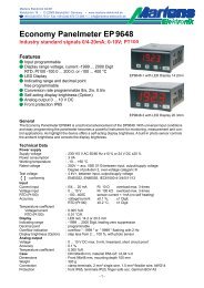
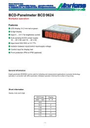
Connection diagram<br />
Supply voltage<br />
Analog output 0/4 ... 20 mA, 0/2 ... 10 V DC<br />
Alarm outputs<br />
A1 ... A2<br />
Pt1<strong>00</strong>/Pt1<strong>00</strong>0 3-wire,<br />
2-wire (link terminal 35-36)<br />
Dimensions Terminals 21 - 28<br />
Terminals 11 - 18<br />
-area<br />
Thermocouple type J, K, N, S<br />
Terminals 41 - 48<br />
Terminals 31 - 38<br />
- 3 -
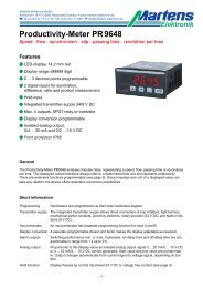
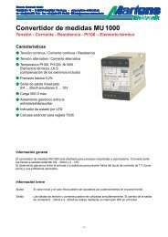
Controls and indicators<br />
Device name<br />
Measured value<br />
Input probe<br />
Alarm output A1<br />
Alarm output A2<br />
Alarm outputs<br />
A3 and A4<br />
not available<br />
Power-ON LED<br />
Parameter<br />
button<br />
Up/down buttons<br />
Description<br />
The operation of the device is implemented in 2 levels. The required parameter is called up with the button .<br />
The selection within a parameter and the setting-adjustment of a value is implemented with the<br />
buttons and .<br />
Button combinations (press buttons simultaneously):<br />
+ 1 parameter back<br />
+ Parameter is set to "0" or minimum value.<br />
After the switching on the supply voltage, the device initializes itself. In the display the message indicating device<br />
type and software version is shown. After the initialization, the device is running in the working level. The<br />
peak value storage is called up and the setpoints of the alarm outputs can be programmed.<br />
The configuration level is called up by activation of the button for 2 seconds. In this case, all parameters<br />
which determine the properties of the device are programmed. After the last menu item, or if no button is<br />
pressed for longer than 2 minutes, a skip-back into the working level is implemented automatically and the current<br />
measured value is indicated in the display. The configuration level can be exited at any time by holding<br />
down button for 2 seconds.<br />
Error reports<br />
In case of occurring faults, the messages are shown on the display in plain text. This simplifies location of the<br />
error. See explanation page 10.<br />
Operational startup reference!<br />
The device is preset with an ex-works default setting. Therefore it must be adapted to each special application.<br />
See Page 6.<br />
$Requirements<br />
- It is necassary to keep the conditions of the ATEX EC-Type Examination Certificate.<br />
- The device must be installed in dry and good monitored rooms.<br />
- If the intrinsinc safety input is connected to the dust hazardous area of zone 20 or 21, it has to be ensured<br />
that the corresponding devices in this circuit have the requirements of catagory 1D or 2D.<br />
- Reparing and design modifications are only allowed at works.<br />
- 4 -
Note on the representation<br />
Parameter appears only with corresponding configuration<br />
Parameter appears only with corresponding equipment version<br />
Working level<br />
Display<br />
Description<br />
<strong>TG50Ex</strong><br />
25.0C<br />
Input: Pt1<strong>00</strong><br />
Temperature<br />
25.0 C<br />
A1: 20.0 A2: 15.0<br />
Input: Pt1<strong>00</strong><br />
Actual-value displays<br />
Change between the two representations for the actual-value<br />
display with the buttons and .<br />
Only the current value can either be displayed or, in addition,<br />
the adjusted values for the switching points of<br />
the alarm outputs. This selection is stored and is also<br />
retained after a voltage breakdown.<br />
Peak value display<br />
MAX 35.0C<br />
MIN 0.0C<br />
Reset with <br />
Peak value display<br />
for minimum and maximum measured value.<br />
Deletion of the values with the button<br />
or with every power cut-off.<br />
Setpoint<br />
Fault det.<br />
Input<br />
Alarm output 1<br />
MIN<br />
Setpoint alarm output A1 (switching function MIN or MAX)<br />
Allocation of the fault detection in the measuring circuit (it belongs to the input; break<br />
of wire or short-circuit) with buttons and .<br />
Setpoint<br />
20.0C<br />
MAX<br />
Setpoint alarm output A1 (switching function MIN or MAX)<br />
Setting possible from -9999 ... 9999 Digit<br />
with buttons and .<br />
Alarm output 1<br />
- 5 -
Configuration level<br />
Display<br />
Description (represented values are default settings)<br />
<strong>TG50Ex</strong><br />
25.0C<br />
Working level<br />
Input: Pt1<strong>00</strong><br />
1<br />
<strong>TG50Ex</strong><br />
Language<br />
Input<br />
Select language<br />
Press 2s<br />
<br />
1.1<br />
<strong>TG50Ex</strong><br />
deutsch<br />
english<br />
Select language<br />
User Language<br />
deutsch<br />
english<br />
Selection with buttons and .<br />
2<br />
<strong>TG50Ex</strong><br />
Language<br />
Input<br />
<br />
2.1<br />
Input signal<br />
Pt1<strong>00</strong><br />
Pt1<strong>00</strong>0<br />
<br />
Input signal<br />
RTD:<br />
Pt1<strong>00</strong> : -1<strong>00</strong>.0 ... 6<strong>00</strong>.0 °C/-1<strong>00</strong> ... 6<strong>00</strong> °C<br />
Pt1<strong>00</strong>0 : -1<strong>00</strong>.0 ... 3<strong>00</strong>.0 °C/-1<strong>00</strong> ... 3<strong>00</strong> °C<br />
Thermocouples:<br />
Type J : Fe-CuNi -1<strong>00</strong>.0 ... 8<strong>00</strong>.0°C/-1<strong>00</strong> ... 8<strong>00</strong> °C<br />
Type K : NiCr-Ni -150 ... 12<strong>00</strong>°C<br />
Type N : NiCrSi-NiSi -150 ... 12<strong>00</strong>°C<br />
Type S : Pt10Rh-Pt -50 ... 16<strong>00</strong>°C<br />
Selection with buttons and .<br />
2.2<br />
Digital filter<br />
OFF<br />
Digital filter<br />
OFF or in steps of 0.5 s in the range from 0.5 ... 40s<br />
Selection with buttons and .<br />
Input signal<br />
3<br />
<strong>TG50Ex</strong><br />
Input<br />
Display<br />
<br />
<br />
3.1<br />
Contrast<br />
▌▌▌▌▌▌▌▌▌▌<br />
65%<br />
Display<br />
Display contrast<br />
Setting possible from 0 ... 1<strong>00</strong>% with buttons and .<br />
3.2<br />
Unit<br />
C<br />
F<br />
Display<br />
Display unit<br />
°C<br />
°F<br />
Selection with buttons and .<br />
Continue page 7<br />
- 6 -
3.3<br />
Decimal place<br />
0<br />
0.0<br />
Display<br />
Number of decimal places<br />
0; 0.0<br />
Selection with buttons and .<br />
Only available with RTD and thermocouple probe type J.<br />
3.4<br />
Correction<br />
Display<br />
0C<br />
Measured value correction<br />
Setting possible from -9999 ... 9999 Digit<br />
with buttons and .<br />
4<br />
<strong>TG50Ex</strong><br />
Display<br />
Output<br />
<br />
<br />
4.1<br />
Analog output<br />
0-20mA<br />
4-20mA<br />
(2-10V)<br />
Selection of the analog output<br />
0 - 20mA (0-10 V DC) or<br />
4 - 20 mA (2-10 V DC)<br />
Selection with buttons and .<br />
Automatic changeover to voltage signal in case of load impedance<br />
> 5<strong>00</strong> Ω.<br />
4.2<br />
Start value<br />
0C<br />
Start value analog output<br />
Setting possible from -9999 ... 9999 Digit<br />
with buttons and .<br />
Analog output<br />
4.3<br />
End value<br />
Analog output<br />
1<strong>00</strong>C<br />
End value analog output<br />
Setting possible from -9999 ... 9999 Digit<br />
with buttons and .<br />
Note:<br />
If start value > end value , the output works with a<br />
decreasing characteristic.<br />
4.4<br />
Correct. analog output<br />
NO<br />
YES<br />
Correction analog output<br />
Selection with buttons and .<br />
NO<br />
YES<br />
Continue page 9<br />
4.5 4.4.1<br />
Continue page 8<br />
- 7 -
4.4.1<br />
Correct. analog output<br />
4.<strong>00</strong>0mA<br />
Correction start value analog output<br />
Setting possible in the range ±2 mA or ±1 V<br />
with buttons and .<br />
Start value (2.<strong>00</strong>0V)<br />
4.4.2<br />
Correct. analog output<br />
20.<strong>00</strong>0mA<br />
Correction end value analog output<br />
Setting possible in the range ±2 mA or ±1 V<br />
with buttons and .<br />
End value (10.<strong>00</strong>0V)<br />
4.5<br />
Fault action<br />
>21 mA<br />
10.5V)<br />
Fault action of the analog output for break of wire or<br />
short-circuit in the measuring circuit.<br />
> 21mA at analog output 0-20/4-20 mA<br />
4.6.1.3<br />
Switch-on delay time<br />
0:<strong>00</strong>:<strong>00</strong><br />
h : mm : ss<br />
Alarm output 1<br />
Switch-on delay time alarm output A1<br />
Setting possible from<br />
0:<strong>00</strong>:<strong>00</strong> ... 9:<strong>00</strong>:<strong>00</strong> (h:mm:ss)<br />
with buttons and .<br />
4.6.1.4<br />
Switch-off delay time<br />
0:<strong>00</strong>:<strong>00</strong><br />
h : mm : ss<br />
Alarm output 1<br />
Switch-off delay time alarm output A1<br />
Setting possible from<br />
0:<strong>00</strong>:<strong>00</strong> ... 9:<strong>00</strong>:<strong>00</strong> (h:mm:ss)<br />
with buttons and .<br />
Note: The parameter settings for A2<br />
have to be configured in the same way.<br />
4.7<br />
Simulation<br />
25C<br />
Simulation of the input signal<br />
Der <strong>TG50Ex</strong> works as actuator. The analog output changes in<br />
the programmed range.<br />
Setting possisible in the programmed range<br />
with buttons and .<br />
This parameter will not be excited automatically<br />
after 120 seconds.<br />
5<br />
<strong>TG50Ex</strong><br />
Output<br />
Lock<br />
<br />
<br />
5.1<br />
Parameter lock<br />
OFF<br />
CONFIG<br />
<br />
Parameter lock<br />
OFF : no parameters locked<br />
CONFIG : Configuration level locked<br />
ALL : all parameters locked<br />
Selection with buttons and .<br />
6<br />
<strong>TG50Ex</strong><br />
Lock<br />
Code<br />
<br />
<br />
6.1<br />
Factory settings<br />
Code<br />
<strong>00</strong><strong>00</strong><br />
Code for Factory settings<br />
7<br />
<strong>TG50Ex</strong><br />
Code<br />
End<br />
<br />
<strong>TG50Ex</strong><br />
25.0C<br />
Return to the working level<br />
Input: Pt1<strong>00</strong><br />
- 9 -
Error reports<br />
Description<br />
Caution!<br />
Parameter<br />
locked<br />
switched on<br />
The parameter can not be changed, because the parameter lock for the configuration<br />
level, or work and configuration level, is activated.<br />
Caution!<br />
Undervoltage<br />
Supply voltage to low<br />
Caution!<br />
XX Parameter<br />
error<br />
Please check<br />
At the check-up of the parameter memory, XX errors are detectet. The incorrect<br />
parameter are resetted to the factoty settings. Please check and correct parameters<br />
if necessary.<br />
Caution!<br />
XX Parameter<br />
error<br />
Calibration necessary<br />
As before, but the factory settings are incorrect. The device must be checked<br />
at works.<br />
Change of decimals<br />
Some parameters not<br />
representable!<br />
Adapt parameters<br />
automatically<br />
Yes<br />
No<br />
Change of decimal places<br />
While changing number of decimal places, some parameters can be converted, but<br />
however, not represented!<br />
Selection "No" : Change of the decimal places is not carried out.<br />
Selection "Yes" : Decimal places are changed automatically, where the affected parameters<br />
are set to the maximum possible value. A subsequent verification of the accepted<br />
parameters is absolutely necessary.<br />
<strong>TG50Ex</strong><br />
Fault<br />
input<br />
Input: 9999C<br />
Break of wire or short-circuit in the measuring circuit.<br />
Text Input: 9999C is flashing.<br />
- 10 -
- 11 -
Ordering code<br />
1. 2. 3. 4. 5. 6.<br />
<strong>TG50Ex</strong> - - - - - -<br />
1. Input<br />
3 Pt1<strong>00</strong><br />
Pt1<strong>00</strong>0<br />
Thermocouple<br />
3-wire<br />
3-wire<br />
J (Fe-CuNi)<br />
K (NiCr-Ni)<br />
N (NiCrSi-NiSi)<br />
S (Pt10Rh-Pt)<br />
Inputs intrinsically safe<br />
-1<strong>00</strong>.0 ... 6<strong>00</strong>.0 °C/-1<strong>00</strong> ... 6<strong>00</strong> °C<br />
-1<strong>00</strong>.0 ... 3<strong>00</strong>.0 °C/-1<strong>00</strong> ... 3<strong>00</strong> °C<br />
-1<strong>00</strong>.0 ... 8<strong>00</strong>.0 °C/-1<strong>00</strong> ... 8<strong>00</strong> °C<br />
-150 ... 12<strong>00</strong> °C<br />
-150 ... 12<strong>00</strong> °C<br />
-50 ... 16<strong>00</strong> °C<br />
ATEX II (1) G [Ex ia] IIC/IIB<br />
ATEX II (1) D [Ex iaD]<br />
2. Alarm outputs<br />
2R 2 relay outputs<br />
3. Alarm outputs<br />
<strong>00</strong> not installed<br />
4. Analog output<br />
<strong>00</strong> not installed<br />
AO Analog output<br />
A1, A2 SPDT<br />
(not available)<br />
0/4 ... 20 mA; 0/2 ... 10 V DC<br />
5. Supply voltage<br />
0 230 V AC<br />
1 115 V AC<br />
5 24 V DC<br />
± 10 %<br />
± 10 %<br />
± 15 %<br />
50-60 Hz<br />
50-60 Hz<br />
6. Options<br />
<strong>00</strong><br />
without option<br />
Works configuration according to customer specifications.<br />
01/08-<strong>V2</strong>.0-<strong>00</strong><br />
- 12 -